EP0332497A1 - Wälzlager mit einstellbarer Vorspannung - Google Patents
Wälzlager mit einstellbarer Vorspannung Download PDFInfo
- Publication number
- EP0332497A1 EP0332497A1 EP89400541A EP89400541A EP0332497A1 EP 0332497 A1 EP0332497 A1 EP 0332497A1 EP 89400541 A EP89400541 A EP 89400541A EP 89400541 A EP89400541 A EP 89400541A EP 0332497 A1 EP0332497 A1 EP 0332497A1
- Authority
- EP
- European Patent Office
- Prior art keywords
- bearing according
- ring
- support
- housing
- elastic member
- Prior art date
- Legal status (The legal status is an assumption and is not a legal conclusion. Google has not performed a legal analysis and makes no representation as to the accuracy of the status listed.)
- Granted
Links
- 238000005096 rolling process Methods 0.000 claims abstract description 22
- 230000036316 preload Effects 0.000 claims description 14
- 230000007246 mechanism Effects 0.000 claims description 13
- 230000002093 peripheral effect Effects 0.000 claims description 4
- 238000004519 manufacturing process Methods 0.000 description 5
- 230000009471 action Effects 0.000 description 2
- 230000000295 complement effect Effects 0.000 description 2
- 238000009434 installation Methods 0.000 description 2
- 238000000034 method Methods 0.000 description 2
- 230000009467 reduction Effects 0.000 description 2
- 240000008042 Zea mays Species 0.000 description 1
- 239000011324 bead Substances 0.000 description 1
- 230000008859 change Effects 0.000 description 1
- 239000006185 dispersion Substances 0.000 description 1
- 238000006073 displacement reaction Methods 0.000 description 1
- 230000000694 effects Effects 0.000 description 1
- 229940082150 encore Drugs 0.000 description 1
- 238000003754 machining Methods 0.000 description 1
- 238000012423 maintenance Methods 0.000 description 1
- 239000000463 material Substances 0.000 description 1
- 230000000717 retained effect Effects 0.000 description 1
- 230000007480 spreading Effects 0.000 description 1
- 238000003892 spreading Methods 0.000 description 1
- 238000007669 thermal treatment Methods 0.000 description 1
- 230000007704 transition Effects 0.000 description 1
- 230000017105 transposition Effects 0.000 description 1
Images

Classifications
-
- F—MECHANICAL ENGINEERING; LIGHTING; HEATING; WEAPONS; BLASTING
- F16—ENGINEERING ELEMENTS AND UNITS; GENERAL MEASURES FOR PRODUCING AND MAINTAINING EFFECTIVE FUNCTIONING OF MACHINES OR INSTALLATIONS; THERMAL INSULATION IN GENERAL
- F16C—SHAFTS; FLEXIBLE SHAFTS; ELEMENTS OR CRANKSHAFT MECHANISMS; ROTARY BODIES OTHER THAN GEARING ELEMENTS; BEARINGS
- F16C25/00—Bearings for exclusively rotary movement adjustable for wear or play
- F16C25/06—Ball or roller bearings
- F16C25/08—Ball or roller bearings self-adjusting
- F16C25/083—Ball or roller bearings self-adjusting with resilient means acting axially on a race ring to preload the bearing
-
- F—MECHANICAL ENGINEERING; LIGHTING; HEATING; WEAPONS; BLASTING
- F16—ENGINEERING ELEMENTS AND UNITS; GENERAL MEASURES FOR PRODUCING AND MAINTAINING EFFECTIVE FUNCTIONING OF MACHINES OR INSTALLATIONS; THERMAL INSULATION IN GENERAL
- F16C—SHAFTS; FLEXIBLE SHAFTS; ELEMENTS OR CRANKSHAFT MECHANISMS; ROTARY BODIES OTHER THAN GEARING ELEMENTS; BEARINGS
- F16C19/00—Bearings with rolling contact, for exclusively rotary movement
- F16C19/02—Bearings with rolling contact, for exclusively rotary movement with bearing balls essentially of the same size in one or more circular rows
- F16C19/14—Bearings with rolling contact, for exclusively rotary movement with bearing balls essentially of the same size in one or more circular rows for both radial and axial load
- F16C19/16—Bearings with rolling contact, for exclusively rotary movement with bearing balls essentially of the same size in one or more circular rows for both radial and axial load with a single row of balls
-
- F—MECHANICAL ENGINEERING; LIGHTING; HEATING; WEAPONS; BLASTING
- F16—ENGINEERING ELEMENTS AND UNITS; GENERAL MEASURES FOR PRODUCING AND MAINTAINING EFFECTIVE FUNCTIONING OF MACHINES OR INSTALLATIONS; THERMAL INSULATION IN GENERAL
- F16C—SHAFTS; FLEXIBLE SHAFTS; ELEMENTS OR CRANKSHAFT MECHANISMS; ROTARY BODIES OTHER THAN GEARING ELEMENTS; BEARINGS
- F16C33/00—Parts of bearings; Special methods for making bearings or parts thereof
- F16C33/30—Parts of ball or roller bearings
- F16C33/58—Raceways; Race rings
- F16C33/60—Raceways; Race rings divided or split, e.g. comprising two juxtaposed rings
-
- F—MECHANICAL ENGINEERING; LIGHTING; HEATING; WEAPONS; BLASTING
- F16—ENGINEERING ELEMENTS AND UNITS; GENERAL MEASURES FOR PRODUCING AND MAINTAINING EFFECTIVE FUNCTIONING OF MACHINES OR INSTALLATIONS; THERMAL INSULATION IN GENERAL
- F16C—SHAFTS; FLEXIBLE SHAFTS; ELEMENTS OR CRANKSHAFT MECHANISMS; ROTARY BODIES OTHER THAN GEARING ELEMENTS; BEARINGS
- F16C33/00—Parts of bearings; Special methods for making bearings or parts thereof
- F16C33/30—Parts of ball or roller bearings
- F16C33/58—Raceways; Race rings
- F16C33/581—Raceways; Race rings integral with other parts, e.g. with housings or machine elements such as shafts or gear wheels
Definitions
- the present invention relates to bearings, in particular ball bearings, with preload and, more particularly, those of them where the preload is adjustable between a first value allowing the maintenance of the rolling elements in the unassembled state and the mounting of the bearing and a second value where the preload is that necessary for proper operation.
- some of them are of a type where at least one of the rings is divided into two parts which are nested, freely movable one inside the other, to transmit the prestress.
- a bearing of this type is, for example, set out in French patent application 86 01 718.
- This document explains how to make a prestressed bearing comprising a housing, an inner ring, an outer ring, rolling elements such as balls placed between the inner and outer rings, at least one elastic piece compressed in the housing between the latter and one of the rings to apply the rolling elements in contact with the inner and outer rings along circular tracks.
- This bearing is such that the balls follow contact tracks which are one located on the inner ring and the other on the outer ring and it is made so that one of the rings consists of two parts on each of which is located one of the contact tracks and which are nested, freely movable one inside the other, to transmit the preload of the elastic part to the rolling elements.
- This type of bearing if it is satisfactory for many applications, however presents implementation difficulties. This is particularly the case when the male part and / or the female part between which it is intended to be placed is of such a nature that it can be used, itself, directly as a ring. In such a case, the qualities of this part, possibly, after having received an appropriate treatment, for example thermal treatment, allow it to be used directly as a contact track on which the rolling elements such as balls roll.
- an appropriate treatment for example thermal treatment
- the object of the invention is to manufacture a prestressed bearing where it is adjustable between a first state where it has a value which allows it to be put in place and a second state where it is put in place, the latter at the value required for the proper functioning of the bearing.
- the subject of the invention is a prestressed bearing comprising a housing, rolling elements circulating along two circular tracks, at least one ring made up of two parts on each of which is located one of these tracks and which are freely movable fitted together. one in the other so as to be able to slide axially and an elastic device cooperating with this housing and at least one of these parts so as to bias axially towards each other these two circular tracks to exert a constraint and where these elements are intended to come to bear on another ring following at least one other circular track .
- This prestressed bearing is remarkable in that this elastic prestressing device is adjustable between a first state where the stress is practically inactive to allow the rolling elements to be placed in contact with this other track of this other ring and a second state where the prestress is active to allow the rolling elements placed in contact with these three tracks at least to circulate with the preload required for normal operation.
- a prestressed bearing according to the invention is intended to be used with a shaft provided with a groove which directly serves as another ring with a circular raceway. It is clear that the invention can be easily transposed so that a bearing according to the invention does not cooperate with a shaft placed axially inside but with a bore which is then placed at its periphery. Transpositions are easy without modifying the invention.
- a prestressed bearing according to the invention comprises, for the embodiments drawn, a housing 10, rolling elements 20 such as balls, optionally and preferably retained in an non-drawn cage, a ring 30 made of two parts 31 and 32 and an elastic prestressing device 50 capable of assuming two states, a first state where the stress is practically inactive to ensure mounting and a second state where the stress is active so that mounting makes the bearing according to the invention can operate normally.
- the housing 10 is thick-walled (Fig.1 and 2) or thin-walled (Fig.3,4,5).
- the manufacturing and machining techniques for this type of housing are conventional.
- the housing 10 is associated directly with one of the parts 31 of the ring 30.
- the housing 10 and the part 31 are, for example, made in one piece and are have the manner of socket 13.
- the other part 32 of the ring 30 is in the form of a cup which can move relatively freely in the housing or socket so as to be able to slide there axially.
- the rolling elements 20, here balls, are intended to bear on at least each of the parts 31 and 32 along circular tracks 231 and 232 respectively.
- the rolling elements are intended to run on at least one other track of another ring.
- this other ring 40 is a shaft which has another track 240 that will be described by the rolling elements.
- This track 240 is, for example, delimited by a groove with a cross section meridian in an arc of a circle.
- the prestressed bearing according to the invention is equipped with an elastic prestressing device 50 adjustable between two states.
- a first state where the preload is practically inactive to allow the mounting of the bearing, here the threading of the shaft, and a second state where the preload is active for mounting allows normal operation of the bearing with the preload required for proper use .
- the elastic adjustable prestressing device 50 comprises a support 51, retaining means 52 and an elastic member 53.
- the support 51 is in the manner of a crown 510 allowing the free passage of the other ring 40 here the tree.
- the retaining means 52 are intended to secure the support 51 to the housing 10. These retaining means are adjustable between a first position so as to place the device in its first state and at least a second position to place the device in its second state.
- the support 51 and the retaining means are made in one piece.
- the support and the retaining means can be distinct in the form of separate components.
- the elastic member 53 of the rolling device according to the invention is, for example, a coil spring 530 one end of which rests against the support 51 and the other end of which rests against the part 32, as illustrated .
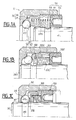
- a first embodiment of a bearing according to the invention is shown in different stages of its installation.
- the retaining means 52 are in the form of a screw and nut mechanism 520.
- the support 51 takes the form of a screw carrying threads 5201 which are engaged in a thread 5202 formed in the housing 10.
- the coil spring 530 is applied against a flat surface in a crown 510 of the support 51 and a gutter 320 formed in the other part 32 which is in the manner of a cup.
- Fig. 1A the embodiment of a bearing according to the invention is illustrated in the position occupied by the elastic device when it is in its first state where the prestressing is practically inactive to allow mounting.
- the retaining means are practically loosened and released from the housing.
- the coil spring 530 which constitutes the elastic member is practically not bandaged.
- the other ring 40 here the shaft with its other track 240 which is in the form of a groove, is just engaged and occupies the position where it is illustrated.
- Fig.1B is shown an intermediate step where the elastic device is always in its first state.
- a bevel or chamfer 241 meets the balls 20 and pushes them outward.
- the balls separate the two parts 31 and 32 of the ring 30 from each other due to the small force exerted by the spring 530 which is practically not bandaged.
- the balls 20 come into line with the groove 240 and engage therein under the action of the spring 530 and the other part 32 of the ring 30 returns to its initial position.
- This situation is that illustrated in Fig. 1C partly in broken lines.
- Fig.2A, 2B and 2C where an alternative embodiment of the embodiment of Fig.1 is illustrated.
- the elastic member 53 is split and there is associated with it an elastic element 54 here another coil spring 540 whose characteristics are different from those of the coil spring 530.
- the support 51 in crown 510 is provided with a rib or bead 511 which separates the two springs and the part 32 has a double stepped gutter 320.
- this embodiment is analogous to that of FIG. 1.
- Fig.2A, 2B and 2C correspond to the situations illustrated in Fig.1A, 1B and 1C, this is why we will not go into it any further.
- the coil spring 530 exerts practically no stress when the device is in its first state illustrated in FIG. 2A and a relatively very small stress is exerted by the coil spring 540.
- a relatively very small stress is exerted by the coil spring 540.
- the value of the initial prestress can be adjusted precisely.
- the support can be such that the spring 530 rests just against the support or it is somewhat pre-banded.
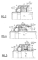
- FIGS. 3, 4 and 5 where other alternative embodiments of the bearing according to the invention are shown. These figures correspond to the situation of Fig.1C and 2C where the other ring is put in place. These various figures differ essentially in the embodiments of the retaining means 52.
- these means 52 are constituted by snap-on mechanisms 521.
- the snap mechanism 521 consists of a stop 5211 associated with the housing 10.
- This stop 5211 is in the form of at least one groove (Fig. 3, 5) or a flange (Fig. 4).
- This mechanism also includes an edge 5215 associated with the support 51. In FIGS. 3 and 5, this edge is in the manner of a flange and in FIG. 4 in the manner of two successive lugs.
- the support 51 and the retaining means 52 are in one piece. They are obtained from thin sheets, of suitable material, which are shaped for example by conventional stamping techniques. In Fig.4, the pins have a certain elasticity so that they can successively cross the rim.
- the latching mechanism 521 is associated with a sleeve 55 which is mounted on the support 51 by means of a frangible connection 550.
- This frangible connection 550 consists of tabs 551 carried by the sleeve 55 which are engaged in cutouts 552 complementary to the support 51. These tabs 551 are folded down, as illustrated, so as to retain the spring 530 in the compressed state.
Landscapes
- Engineering & Computer Science (AREA)
- General Engineering & Computer Science (AREA)
- Mechanical Engineering (AREA)
- Support Of The Bearing (AREA)
Applications Claiming Priority (2)
| Application Number | Priority Date | Filing Date | Title |
|---|---|---|---|
| FR8802776 | 1988-03-04 | ||
| FR8802776A FR2628160B1 (fr) | 1988-03-04 | 1988-03-04 | Roulement a precontrainte reglable |
Publications (2)
| Publication Number | Publication Date |
|---|---|
| EP0332497A1 true EP0332497A1 (de) | 1989-09-13 |
| EP0332497B1 EP0332497B1 (de) | 1993-01-20 |
Family
ID=9363921
Family Applications (1)
| Application Number | Title | Priority Date | Filing Date |
|---|---|---|---|
| EP89400541A Expired - Lifetime EP0332497B1 (de) | 1988-03-04 | 1989-02-27 | Wälzlager mit einstellbarer Vorspannung |
Country Status (8)
| Country | Link |
|---|---|
| US (1) | US4913564A (de) |
| EP (1) | EP0332497B1 (de) |
| JP (1) | JPH01269714A (de) |
| BR (1) | BR8900998A (de) |
| DE (1) | DE68904444T2 (de) |
| ES (1) | ES2037437T3 (de) |
| FR (1) | FR2628160B1 (de) |
| IN (1) | IN172123B (de) |
Cited By (7)
| Publication number | Priority date | Publication date | Assignee | Title |
|---|---|---|---|---|
| DE4108827A1 (de) * | 1991-03-18 | 1992-09-24 | Schaeffler Waelzlager Kg | Spielfreies kugellager |
| DE4224992A1 (de) * | 1992-07-29 | 1994-02-03 | Schaeffler Waelzlager Kg | Spielfreies Radialkugellager |
| DE4231272A1 (de) * | 1992-09-18 | 1994-03-24 | Wagner Gmbh & Co Fahrzeugteile | Kugellager |
| FR2730282A1 (fr) * | 1995-02-07 | 1996-08-09 | Nadella | Roulement radial a billes precontraint et deboitable et son application a une direction de vehicule |
| FR2824878A1 (fr) * | 2001-05-16 | 2002-11-22 | Nadella | Ensemble de roulement a contact oblique, notamment pour colonne de direction de vehicule automobile |
| WO2010054640A3 (de) * | 2008-11-13 | 2011-02-24 | Schaeffler Technologies Gmbh & Co. Kg | Lagereinheit, insbesondere zur lagerung eines laufrades, einer spindel oder eines anderen maschinenaggregats |
| FR3032481A1 (fr) * | 2015-02-09 | 2016-08-12 | Snecma | Palier ameliore pour machine tournante realisant un equilibrage de charge axiale |
Families Citing this family (25)
| Publication number | Priority date | Publication date | Assignee | Title |
|---|---|---|---|---|
| FR2669086B2 (fr) * | 1988-03-04 | 1995-03-03 | Nadella | Roulement perfectionne a precontrainte. |
| DE3842717A1 (de) * | 1988-12-19 | 1990-06-21 | Schaeffler Waelzlager Kg | Lagerung einer welle in einem rollenlager |
| DE9011113U1 (de) * | 1990-07-27 | 1990-11-08 | Paul Pleiger Maschinenfabrik GmbH & Co KG, 5810 Witten | Absperrhahn |
| GB2248475B (en) * | 1990-10-04 | 1994-10-19 | Lowe Edwin Ltd | Improvements in and relating to conveyor idlers and rollers and bearing housing assemblies for them |
| DE69117260T2 (de) * | 1990-11-08 | 1996-08-22 | Nadella | Vorgespanntes Wälzlager |
| US5316393A (en) * | 1992-09-30 | 1994-05-31 | The United States Of America As Represented By The Secretary Of The Navy | Duplex rolling element bearing mounting for ensuring preload control |
| US5421657A (en) * | 1993-09-16 | 1995-06-06 | Caterpillar Inc. | Apparatus for preloading a torque converter thrust bearing |
| WO1997006057A1 (en) * | 1995-08-09 | 1997-02-20 | Dowty Aerospace Gloucester Limited | A bearing and a method of disassembling such a bearing |
| JP2001140869A (ja) * | 1999-11-19 | 2001-05-22 | Minebea Co Ltd | 複列軸受 |
| DE102004021138A1 (de) | 2004-04-29 | 2005-11-24 | Siemens Ag | Elektrische Maschine und deren Lager |
| DE102004048720A1 (de) * | 2004-10-06 | 2006-04-13 | Fag Kugelfischer Ag & Co. Ohg | Kugellager, insbesondere zur Lagerung der Hauptspindel einer Werkzeugmaschine |
| DE102008000506A1 (de) * | 2008-03-04 | 2009-09-17 | Zf Lenksysteme Gmbh | Schraubradgetriebe mit axial elastischer Wellenlagerung und damit ausgestattete elektrische Hilfskraftlenkung |
| GB2475719A (en) * | 2009-11-27 | 2011-06-01 | Ge Aviat Systems Ltd | Preloaded propeller blade assembly |
| US8475320B2 (en) * | 2011-05-19 | 2013-07-02 | American Axle & Manufacturing, Inc. | Bearing preload adjuster |
| US9066596B2 (en) * | 2012-11-14 | 2015-06-30 | Jeffrey L. Clark | Seating assembly |
| FR3003914B1 (fr) * | 2013-03-28 | 2015-10-16 | Snecma | Palier a double precharge interne |
| DE102014204101A1 (de) * | 2013-04-23 | 2014-10-23 | Schaeffler Technologies AG & Co. KG | Kompakte, integrierte Vorspannvorrichtung für Lager |
| MX370831B (es) * | 2013-07-26 | 2020-01-07 | w hughes Mark | Tuerca de bloqueo. |
| JP6253955B2 (ja) * | 2013-11-13 | 2017-12-27 | Ntn株式会社 | 軸受予圧装置 |
| DE102013225068A1 (de) * | 2013-12-06 | 2015-06-11 | Schaeffler Technologies AG & Co. KG | Lenkungslager zur Lagerung einer Lenksäule eines Kraftfahrzeugs |
| CN103883615A (zh) * | 2014-03-10 | 2014-06-25 | 苏州捷德瑞精密机械有限公司 | 一种精密轴承 |
| CN104930067A (zh) * | 2015-05-08 | 2015-09-23 | 江苏联动轴承有限公司 | 一种高效角接触轴承的装球装置 |
| DE102016114678A1 (de) * | 2016-08-08 | 2018-02-08 | Thyssenkrupp Ag | Drehlageranordnung für eine Lenksäule eines Kraftfahrzeugs |
| US11353061B1 (en) * | 2020-12-14 | 2022-06-07 | Schaeffler Technologies AG & Co. KG | Preloaded shaft assembly |
| DE102021131574A1 (de) | 2021-12-01 | 2023-06-01 | Krones Aktiengesellschaft | Lageranordnung zum Lagern eines Behälterbehandlungskarussells gegen ein Grundgestell einer Behälterbehandlungsvorrichtung in einer Getränkeabfüllanlage |
Citations (4)
| Publication number | Priority date | Publication date | Assignee | Title |
|---|---|---|---|---|
| FR784279A (fr) * | 1934-01-27 | 1935-07-22 | Louis Mueller Et Compagnie M | Palier à billes |
| CH416229A (fr) * | 1963-04-20 | 1966-06-30 | Birfield Eng Ltd | Dispositif de montage d'un élément tubulaire sur un arbre |
| DE2115283A1 (de) * | 1971-03-30 | 1972-10-12 | Vdo Schindling | Spurlagerung einer Welle |
| DE8806186U1 (de) * | 1988-05-10 | 1988-06-23 | Fa. Carl Zeiss, 7920 Heidenheim | Hochgenaues Kugellager |
Family Cites Families (5)
| Publication number | Priority date | Publication date | Assignee | Title |
|---|---|---|---|---|
| DE287103C (de) * | 1900-01-01 | |||
| GB1085224A (en) * | 1963-07-03 | 1967-09-27 | Birfield Eng Ltd | Improvements in or relating to mounting means |
| US4325590A (en) * | 1980-05-22 | 1982-04-20 | Textron Inc. | Self-contained pre-loaded antifriction bearing assembly |
| SE439047B (sv) * | 1983-05-24 | 1985-05-28 | Skf Nova Ab | Forspenningsanordning vid ett vinkelkontaktlager |
| FR2594189B1 (fr) * | 1986-02-07 | 1988-05-27 | Nadella | Roulement a billes a precontrainte et procede et outil pour sa fabrication |
-
1988
- 1988-03-04 FR FR8802776A patent/FR2628160B1/fr not_active Expired - Fee Related
-
1989
- 1989-02-27 EP EP89400541A patent/EP0332497B1/de not_active Expired - Lifetime
- 1989-02-27 ES ES198989400541T patent/ES2037437T3/es not_active Expired - Lifetime
- 1989-02-27 IN IN161/MAS/89A patent/IN172123B/en unknown
- 1989-02-27 DE DE8989400541T patent/DE68904444T2/de not_active Expired - Fee Related
- 1989-03-01 US US07/317,428 patent/US4913564A/en not_active Expired - Fee Related
- 1989-03-03 BR BR898900998A patent/BR8900998A/pt not_active IP Right Cessation
- 1989-03-04 JP JP1052740A patent/JPH01269714A/ja active Pending
Patent Citations (4)
| Publication number | Priority date | Publication date | Assignee | Title |
|---|---|---|---|---|
| FR784279A (fr) * | 1934-01-27 | 1935-07-22 | Louis Mueller Et Compagnie M | Palier à billes |
| CH416229A (fr) * | 1963-04-20 | 1966-06-30 | Birfield Eng Ltd | Dispositif de montage d'un élément tubulaire sur un arbre |
| DE2115283A1 (de) * | 1971-03-30 | 1972-10-12 | Vdo Schindling | Spurlagerung einer Welle |
| DE8806186U1 (de) * | 1988-05-10 | 1988-06-23 | Fa. Carl Zeiss, 7920 Heidenheim | Hochgenaues Kugellager |
Cited By (9)
| Publication number | Priority date | Publication date | Assignee | Title |
|---|---|---|---|---|
| DE4108827A1 (de) * | 1991-03-18 | 1992-09-24 | Schaeffler Waelzlager Kg | Spielfreies kugellager |
| DE4224992A1 (de) * | 1992-07-29 | 1994-02-03 | Schaeffler Waelzlager Kg | Spielfreies Radialkugellager |
| DE4393663C1 (de) * | 1992-07-29 | 1997-02-20 | Schaeffler Waelzlager Kg | Spielfreies Radialkugellager |
| DE4231272A1 (de) * | 1992-09-18 | 1994-03-24 | Wagner Gmbh & Co Fahrzeugteile | Kugellager |
| FR2730282A1 (fr) * | 1995-02-07 | 1996-08-09 | Nadella | Roulement radial a billes precontraint et deboitable et son application a une direction de vehicule |
| FR2824878A1 (fr) * | 2001-05-16 | 2002-11-22 | Nadella | Ensemble de roulement a contact oblique, notamment pour colonne de direction de vehicule automobile |
| WO2010054640A3 (de) * | 2008-11-13 | 2011-02-24 | Schaeffler Technologies Gmbh & Co. Kg | Lagereinheit, insbesondere zur lagerung eines laufrades, einer spindel oder eines anderen maschinenaggregats |
| FR3032481A1 (fr) * | 2015-02-09 | 2016-08-12 | Snecma | Palier ameliore pour machine tournante realisant un equilibrage de charge axiale |
| WO2016128659A1 (fr) * | 2015-02-09 | 2016-08-18 | Snecma | Roulement monté avec une bague extérieure en deux pièces en appui contre une butée du carter par l'intermédiaire d'un ressort exerçant une précharge axiale |
Also Published As
| Publication number | Publication date |
|---|---|
| JPH01269714A (ja) | 1989-10-27 |
| EP0332497B1 (de) | 1993-01-20 |
| IN172123B (de) | 1993-04-10 |
| ES2037437T3 (es) | 1993-06-16 |
| BR8900998A (pt) | 1989-10-24 |
| FR2628160B1 (fr) | 1994-03-18 |
| US4913564A (en) | 1990-04-03 |
| FR2628160A1 (fr) | 1989-09-08 |
| DE68904444D1 (de) | 1993-03-04 |
| DE68904444T2 (de) | 1993-05-13 |
Similar Documents
| Publication | Publication Date | Title |
|---|---|---|
| EP0332497B1 (de) | Wälzlager mit einstellbarer Vorspannung | |
| EP0025750A1 (de) | Entkuppelbare Rollenschrauben- und Nutvorrichtung | |
| FR2619880A1 (fr) | Butee de debrayage, notamment pour vehicules automobiles | |
| FR2859512A1 (fr) | Systeme de freinage | |
| EP0402198B1 (de) | Verriegelungsmutter | |
| WO2009115519A1 (fr) | Organe de pivotement | |
| FR2489908A1 (fr) | Embrayage a friction | |
| EP2978985B1 (de) | Entkoppelbares axialschublager mit interner vorspannung | |
| FR2713050A1 (fr) | Ensemble à casque et visière. | |
| FR2588052A1 (fr) | Ensemble a butee de debrayage | |
| EP1298340B1 (de) | Synchronisiereinrichtung für Schaltgetriebe von Kraftfahrzeugen | |
| FR2546999A1 (fr) | Mecanisme d'embrayage a piece rapportee sur le plateau de pression | |
| EP0486343B1 (de) | Vorgespanntes Wälzlager | |
| EP1500460A1 (de) | Verfahren zur Herstellung eines Befestigungskragens mit einem allmählichen Übergang | |
| FR2629380A1 (fr) | Dispositif d'indexation pour tours revolver et analogues | |
| FR2676490A1 (fr) | Dispositif de surete apte a realiser un blocage du barillet en cas de tentative de forcage et mecanisme de serrure equipe de ce dispositif. | |
| EP3140562A1 (de) | Elektromechanischer stellantrieb mit kugelgewindetrieb für eine kupplung | |
| FR2813359A1 (fr) | Dispositif de maintien d'un billage dans un moyeu d'un ensemble synchroniseur pour vehicule automobile | |
| EP1836412B1 (de) | Vorrichtung zum auflegen/abnehmen eines bandes und verfahren zum installieren/entfernen eines bandes | |
| EP1201952B1 (de) | Synchronisierung mit verringerter, störender Reibung | |
| CH698675B1 (fr) | Palier amortisseur de chocs pour pièce d'horlogerie. | |
| EP2016301A1 (de) | Synchronisiervorrichtung mit umkehrhebel | |
| FR2753295A1 (fr) | Boitier de rangement notamment pour disques compacts | |
| EP0049675A1 (de) | Elastische Abstandshülse für den Einbau von Kugellagern | |
| FR2669086A2 (fr) | Roulement perfectionne a precontrainte. |
Legal Events
| Date | Code | Title | Description |
|---|---|---|---|
| PUAI | Public reference made under article 153(3) epc to a published international application that has entered the european phase |
Free format text: ORIGINAL CODE: 0009012 |
|
| AK | Designated contracting states |
Kind code of ref document: A1 Designated state(s): CH DE ES GB IT LI NL SE |
|
| 17P | Request for examination filed |
Effective date: 19891005 |
|
| 17Q | First examination report despatched |
Effective date: 19910322 |
|
| GRAA | (expected) grant |
Free format text: ORIGINAL CODE: 0009210 |
|
| ITF | It: translation for a ep patent filed | ||
| AK | Designated contracting states |
Kind code of ref document: B1 Designated state(s): CH DE ES GB IT LI NL SE |
|
| PG25 | Lapsed in a contracting state [announced via postgrant information from national office to epo] |
Ref country code: SE Effective date: 19930120 Ref country code: NL Effective date: 19930120 |
|
| REF | Corresponds to: |
Ref document number: 68904444 Country of ref document: DE Date of ref document: 19930304 |
|
| GBT | Gb: translation of ep patent filed (gb section 77(6)(a)/1977) |
Effective date: 19930208 |
|
| NLV1 | Nl: lapsed or annulled due to failure to fulfill the requirements of art. 29p and 29m of the patents act | ||
| REG | Reference to a national code |
Ref country code: ES Ref legal event code: FG2A Ref document number: 2037437 Country of ref document: ES Kind code of ref document: T3 |
|
| PLBE | No opposition filed within time limit |
Free format text: ORIGINAL CODE: 0009261 |
|
| STAA | Information on the status of an ep patent application or granted ep patent |
Free format text: STATUS: NO OPPOSITION FILED WITHIN TIME LIMIT |
|
| 26N | No opposition filed | ||
| PGFP | Annual fee paid to national office [announced via postgrant information from national office to epo] |
Ref country code: CH Payment date: 19950214 Year of fee payment: 7 |
|
| PGFP | Annual fee paid to national office [announced via postgrant information from national office to epo] |
Ref country code: ES Payment date: 19950228 Year of fee payment: 7 |
|
| PGFP | Annual fee paid to national office [announced via postgrant information from national office to epo] |
Ref country code: GB Payment date: 19960220 Year of fee payment: 8 |
|
| PG25 | Lapsed in a contracting state [announced via postgrant information from national office to epo] |
Ref country code: LI Free format text: LAPSE BECAUSE OF NON-PAYMENT OF DUE FEES Effective date: 19960228 Ref country code: ES Free format text: LAPSE BECAUSE OF NON-PAYMENT OF DUE FEES Effective date: 19960228 Ref country code: CH Free format text: LAPSE BECAUSE OF NON-PAYMENT OF DUE FEES Effective date: 19960228 |
|
| REG | Reference to a national code |
Ref country code: CH Ref legal event code: PL |
|
| PGFP | Annual fee paid to national office [announced via postgrant information from national office to epo] |
Ref country code: DE Payment date: 19970124 Year of fee payment: 9 |
|
| PG25 | Lapsed in a contracting state [announced via postgrant information from national office to epo] |
Ref country code: GB Effective date: 19970227 |
|
| GBPC | Gb: european patent ceased through non-payment of renewal fee |
Effective date: 19970227 |
|
| PG25 | Lapsed in a contracting state [announced via postgrant information from national office to epo] |
Ref country code: DE Free format text: LAPSE BECAUSE OF NON-PAYMENT OF DUE FEES Effective date: 19981103 |
|
| REG | Reference to a national code |
Ref country code: ES Ref legal event code: FD2A Effective date: 19990201 |
|
| PG25 | Lapsed in a contracting state [announced via postgrant information from national office to epo] |
Ref country code: IT Free format text: LAPSE BECAUSE OF NON-PAYMENT OF DUE FEES;WARNING: LAPSES OF ITALIAN PATENTS WITH EFFECTIVE DATE BEFORE 2007 MAY HAVE OCCURRED AT ANY TIME BEFORE 2007. THE CORRECT EFFECTIVE DATE MAY BE DIFFERENT FROM THE ONE RECORDED. Effective date: 20050227 |