EP0332637B1 - Sonde pour appareil a ultrasons munie d'un arrangement concave d'elements piezo-electriques - Google Patents
Sonde pour appareil a ultrasons munie d'un arrangement concave d'elements piezo-electriques Download PDFInfo
- Publication number
- EP0332637B1 EP0332637B1 EP87907784A EP87907784A EP0332637B1 EP 0332637 B1 EP0332637 B1 EP 0332637B1 EP 87907784 A EP87907784 A EP 87907784A EP 87907784 A EP87907784 A EP 87907784A EP 0332637 B1 EP0332637 B1 EP 0332637B1
- Authority
- EP
- European Patent Office
- Prior art keywords
- probe
- elements
- fact
- plate
- accordance
- Prior art date
- Legal status (The legal status is an assumption and is not a legal conclusion. Google has not performed a legal analysis and makes no representation as to the accuracy of the status listed.)
- Expired - Lifetime
Links
- 239000000523 sample Substances 0.000 title claims abstract description 36
- 238000002604 ultrasonography Methods 0.000 title claims description 6
- 238000001465 metallisation Methods 0.000 claims abstract description 19
- 230000007704 transition Effects 0.000 claims abstract description 10
- 239000000463 material Substances 0.000 claims description 7
- 238000000926 separation method Methods 0.000 claims 1
- 238000002474 experimental method Methods 0.000 abstract 1
- 239000013078 crystal Substances 0.000 description 8
- 238000004519 manufacturing process Methods 0.000 description 4
- 238000007906 compression Methods 0.000 description 3
- 238000001816 cooling Methods 0.000 description 2
- 230000005684 electric field Effects 0.000 description 2
- 238000005516 engineering process Methods 0.000 description 2
- 239000003292 glue Substances 0.000 description 2
- BQCIDUSAKPWEOX-UHFFFAOYSA-N 1,1-Difluoroethene Chemical compound FC(F)=C BQCIDUSAKPWEOX-UHFFFAOYSA-N 0.000 description 1
- 238000005452 bending Methods 0.000 description 1
- 239000000919 ceramic Substances 0.000 description 1
- 239000002131 composite material Substances 0.000 description 1
- 230000006835 compression Effects 0.000 description 1
- 229920001577 copolymer Polymers 0.000 description 1
- 230000008878 coupling Effects 0.000 description 1
- 238000010168 coupling process Methods 0.000 description 1
- 238000005859 coupling reaction Methods 0.000 description 1
- 230000005284 excitation Effects 0.000 description 1
- 230000002349 favourable effect Effects 0.000 description 1
- 238000010438 heat treatment Methods 0.000 description 1
- 239000011159 matrix material Substances 0.000 description 1
- 230000002093 peripheral effect Effects 0.000 description 1
- 229920003023 plastic Polymers 0.000 description 1
- 239000004033 plastic Substances 0.000 description 1
- 229920000642 polymer Polymers 0.000 description 1
- 229920002635 polyurethane Polymers 0.000 description 1
- 239000004814 polyurethane Substances 0.000 description 1
- 229920002981 polyvinylidene fluoride Polymers 0.000 description 1
- 230000001902 propagating effect Effects 0.000 description 1
- 229920002994 synthetic fiber Polymers 0.000 description 1
- 230000001131 transforming effect Effects 0.000 description 1
Images

Classifications
-
- G—PHYSICS
- G10—MUSICAL INSTRUMENTS; ACOUSTICS
- G10K—SOUND-PRODUCING DEVICES; METHODS OR DEVICES FOR PROTECTING AGAINST, OR FOR DAMPING, NOISE OR OTHER ACOUSTIC WAVES IN GENERAL; ACOUSTICS NOT OTHERWISE PROVIDED FOR
- G10K11/00—Methods or devices for transmitting, conducting or directing sound in general; Methods or devices for protecting against, or for damping, noise or other acoustic waves in general
- G10K11/18—Methods or devices for transmitting, conducting or directing sound
- G10K11/26—Sound-focusing or directing, e.g. scanning
- G10K11/32—Sound-focusing or directing, e.g. scanning characterised by the shape of the source
Definitions
- the present invention relates to a probe for an ultrasonic device provided with a concave arrangement of piezoelectric elements.
- a probe for an ultrasonic device provided with a concave arrangement of piezoelectric elements.
- Such a probe can be used in particular in the medical field in combination with an ultrasound device. It can nevertheless find its application in other fields where ultrasound is used and where, for focusing needs, it is preferable to use probes provided with piezoelectric elements distributed over a concave surface.
- An ultrasound device probe in principle comprises a plurality of piezoelectric transducer elements for transforming electrical signals applied to the elements into mechanical excitations and vice versa. These piezoelectric elements are arranged in the head of the probe according to a matrix type distribution, most often in two dimensions, sometimes in one dimension, for example in a strip.
- the realization of such a probe faced with the need to power electrically, independently, each of the elements is not a simple problem.
- One solution in principle consists in fixing a plate of a piezoelectric crystal to a flexible metallized support, and in making cuts in this plate without too much damage to the support. In this way we obtain the desired distribution of the elements. By having made sufficiently large cuts and by bending the elastic support, it can be imposed a desired concave shape.
- the characteristics of the preamble of claim 1 are known from the Japanese abstract 57181299.
- the support 1 known from this document is heat-deformable and the acoustic transition blade is broken up by saw cuts. It is known from the Japanese abstract 60249500 to join elements 3 to a plate 4. This plate is not described as being an acoustic transition plate.
- the object of the present invention is to remedy these drawbacks by noting that for the desired applications, with a focus imposed by the curvature of the arrangement of the elements, it is not a problem if the vertices of the elements covered with their transition blade touch each other in the concavity of the probe.
- the electrical connection for differentiating all the elements can be made from the rear of the probe, where previously there was the support.
- These electrical connection circuits disturb the rear wave of the probe, which is not important: they do not interfere with the useful operation of the probe.
- the concave arrangements are obtained for piezoelectric elements using flexible blades, possibly heat-deformable.
- the metallizations of the front and rear faces make it possible to apply an electric field parallel to the direction of propagation of the acoustic waves. This arrangement is advantageous because it improves the coupling coefficient between the electric field and the acoustic field.
- the piezoelectric elements comprise, for example, plastic elements such as, for example, the PVF2 or the PVT2F copolymer; a ceramic such as PZT, PZT polymer composite or PBTiO3 or a crystal.
- the subject of the invention is therefore a probe for an ultrasonic device provided with a concave arrangement of piezoelectric elements, these elements each being covered, on their emissive face opposite the concavity, with an acoustic transition plate, characterized in that these blades are adjacent and constitute the same continuous monobloc blade covering a plurality of elements.
- Figure 1 shows a probe according to the invention.
- This comprises a concave arrangement 1 of piezoelectric elements such as 2.
- the concavity is a concavity in two orthogonal dimensions: the surface is left. It can of course be concave in one dimension and in this case the surface is cylindrical.
- the elements are each covered, on their face 3 opposite the concavity, with an acoustic transition blade.
- element 2 its transition blade 4 is partially limited by dashes in the drawing.
- the characteristic of the probe of the invention resides in the fact that adjacent blades constitute the same monobloc blade 5, continuous, covering a plurality of elements, in general all of the elements.
- the blade 5 is provided on its face opposite these elements with a metallization 7 which comes into contact with the metallizations of these elements.
- the other metallizations 8 of the piezoelectric elements can be connected in a conventional manner. These connections can be incorporated into a base 9 which can also serve to maintain and manipulate the probe.
- the presence of the differentiated electrical connections at the location of the metallizations 8 cannot cause disturbance in the acoustic signals transmitted or received because they are located at the rear of the probe with respect to the useful direction P of propagation.
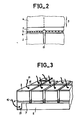
- FIG. 2 shows a detail of embodiment of the probe at a location marked at 10 in FIG. 1.
- glue is applied to a blade 5 previously metallized with a layer 7 a plate of a piezoelectric crystal metallized on its two faces.
- the metallization 7 of the blade is preferably thick: in one example it is between 15 and 20 micrometers.
- the metallization of the crystal is normal, it can be of a much smaller thickness.
- the glue used to fix the crystal on the blade is such that it allows electrical continuity in all places between the two metallizations.
- cuts 11 are made on the rear face of the crystal whose purpose is to separate the elements from one another in the plate.
- the cut 11 has the distinction of being carried out with care.
- its depth extends up to mid-thickness of the metallization 7 of the blade 5. It is known, with flatness tolerances of the order of one micrometer, to carry out the rectification of the surfaces of the blade and of the piezoelectric crystal. With a saw correctly guided with respect to the plane of the arrangement, it is then possible to ensure that the cut does not break the electrical connection formed by the metallization 7.
- FIG. 3 shows how the electrical connection can be made simply on each metallization 8 carried out on the other face of an element.
- thermo-compression technology is used. With this technology, the end 12 of connecting wires 13 is pressed against the metallizations 8. By heating this end at the time of this compression, a sufficient electrical connection is obtained. The same is done with a wire 14 which terminates on a peripheral part 15 of the metallization 7 of the blade 5.
- the arrangement is curved.
- This arrangement can be concave in one dimension or concave, as shown in FIG. 1, in two dimensions.
- the material which constitutes the continuous blade is a deformable material.
- the blade material 5 is even a heat-deformable material.
- this blade is made of a cold polymerizable polyurethane. Under these conditions, it suffices to subject the blade-crystal assembly thus formed and then cut, to a heating-cooling cycle. During this hot cycle, the arrangement is subjected to forces tending to deform it in the desired manner. An appropriate form can be used for this purpose to press against the assembly. During cooling, the whole hardens with the shape that has been imposed on it. After this operation, a base 9 is made for the arrangement by pouring, against the rear faces of the elements, a polymerizable synthetic material. The wires 13 or 14 emerge from this base. They are subsequently connected to the control circuits of the ultrasound device used.
- the materials which constitute the base are preferably chosen from among those likely to have a zero acoustic impedance.
- the contact between the elements and the base is not very intimate.
- the presence of a thin layer of interposed air is even favorable for lowering the value of the rear acoustic impedance. This loose contact is made possible by the choice of a thermo-compression connection as indicated: there is no obligation to bond against the rear faces of the elements a connection device based on a rigid printed circuit.
Landscapes
- Physics & Mathematics (AREA)
- Engineering & Computer Science (AREA)
- Acoustics & Sound (AREA)
- Multimedia (AREA)
- Investigating Or Analyzing Materials By The Use Of Ultrasonic Waves (AREA)
- Transducers For Ultrasonic Waves (AREA)
- Ultra Sonic Daignosis Equipment (AREA)
Description
- La présente invention a pour objet une sonde pour appareil à ultrasons munie d'un arrangement concave d'éléments piézo-électriques. Une telle sonde est utilisable en particulier dans le domaine médical en association avec un appareil de type échographe. Elle peut néanmoins trouver son application dans d'autres domaines où on emploie des ultrasons et où, pour des besoins de focalisation, on a de préférence recours à des sondes munies d'éléments piézo-électriques répartis sur une surface concave.
- Une sonde d'appareil à ultrasons comporte en principe une pluralité d'éléments transducteurs piézo-électriques pour transformer des signaux électriques appliqués aux éléments en excitations mécaniques et réciproquement. Ces éléments piézo-électriques sont arrangés dans la tête de la sonde selon une répartition de type matriciel, le plus souvent à deux dimensions, quelques fois à une dimension par exemple en une barrette. La réalisation d'une telle sonde confrontée à la nécessité d'alimenter électriquement, indépendamment, chacun des éléments n'est pas un problème simple. Une solution de principe consiste à fixer sur un support souple métallisé une plaque d'un cristal piézo-électrique, et à effectuer des découpes dans cette plaque sans entamer trop le support. De cette manière on obtient la distribution recherchée des éléments. En ayant effectué des découpes suffisamment larges et en courbant le support élastique, on peut lui imposer une forme concave voulue. Ce faisant l'alimentation électrique des deux faces des éléments piézo-électriques n'est pas facilement résolue. En effet l'émission acoustique utile se propageant du coté de la concavité, il est malvenu de réaliser sur cette surface des circuits de connexion indépendants. Ceci est d'autant plus génant que pour des raisons de propagation acoustique il est nécessaire de placer au dessus de chacun des éléments une lame de transition acoustique dont l'épaisseur est sensiblement égale au quart de la longueur d'onde de l'onde, qui la traverse, à la fréquence de travail de la sonde. Ce problème de connexion est un frein important au développement des sondes, en particulier celles dont l'arrangement piézo-électrique est bidimentionnel.
- Les caractéristiques du préambule de la revendication 1 sont connues de l'abrégé japonais 57181299. Le support 1 connu de ce document est thermo-déformable et la lame de transition acoustique est morcelée par des traits de scie. Il est connu de l'abrégé japonais 60249500 de joindre des éléments 3 à un plateau 4. Ce plateau n'est pas décrit comme étant une lame de transition acoustique.
- La présente invention a pour objet de remédier à ces inconvénients en remarquant que pour les applications recherchées, avec une focalisation imposée par la courbure de l'arrangement des éléments, il n'est pas gênant que les sommets des éléments recouverts de leur lame de transition se touchent les uns les autres dans la concavité de la sonde. Dans l'invention on a alors eu l'idée d'inverser le problème et d'utiliser une lame de transition commune, métallisée continuement sur toute sa surface, et contre laquelle sont fixés tous les éléments piézo-électriques. Il en résulte que la connexion électrique de différenciation de tous les éléments peut se faire par l'arrière de la sonde, là où auparavant il y avait le support. Ces circuits électriques de connexion perturbent l'onde arrière de la sonde, ce qui est sans importance : ils ne gênent pas le fonctionnement utile de la sonde. On obtient les arrangements concaves d'éléments piézo-électriques en utilisant des lames souples, éventuellement thermo-déformables.
- Les métallisations des faces avant et arrière permettent d'appliquer un champ électrique parallèle à la direction de propagation des ondes acoustiques. Cette disposition est avantageuse car elle améliore le coefficient de couplage entre le champ électrique et le champ acoustique.
- Les éléments piézo-électriques comportent par exemple des éléments en plastique comme par exemple le PVF₂ ou le PVT₂F copolymère ; une céramique comme par exemple le PZT, le PZT composite polymère ou le PBTiO₃ ou un cristal.
- L'invention a donc pour objet une sonde pour appareil à ultrasons munie d'un arrangement concave d'éléments piézo-électriques, ces éléments étant recouverts chacun, sur leur face émissive en regard de la concavité, d'une lame de transition acoustique, caractérisé en ce que ces lames sont adjacentes et constituent une même lame monobloc continue recouvrant une pluralité d'éléments.
- La présente invention sera mieux comprise à la lecture de la description qui suit et à l'examen des figures qui l'accompagnent. Elles ne sont données qu'à titre indicatif et nullement limitatif de l'invention. Les figures montrent :
- figure 1 : une sonde conforme à l'invention;
- figure 2 : un détail de réalisation de la sonde de la figure 1 au cours de son procédé de réalisation;
- figure 3 : un détail de réalisation du circuit de connexion des éléments piézo-électriques.
- La figure 1 représente une sonde conforme à l'invention. Celle-ci comporte un arrangement concave 1 d'éléments piézo-électriques tels que 2. La concavité est une concavité dans deux dimensions orthogonales : la surface est gauche. Elle peut bien entendue être concave dans une dimension et dans ce cas la surface est cylindrique. Les éléments sont recouverts chacun, sur leur face 3 en regard de la concavité, d'une lame de transition acoustique. Par exemple pour l'élément 2 sa lame 4 de transition est limitée en partie par des tirets sur le dessin. La caractéristique de la sonde de l'invention réside dans le fait que des lames adjacentes constituent une même lame monobloc 5, continue, recouvrant une pluralité d'éléments, en général la totalité des éléments. Pour assurer la liaison électrique aux électrodes 6 (obtenues par métallisation) des éléments piézo-électriques, la lame 5 est munie sur sa face en regard de ces éléments d'une métallisation 7 qui vient au contact des métallisations de ces éléments. Les autres métallisations 8 des éléments piézo-électriques peuvent être raccordés d'une manière classique. Ces liaisons peuvent être incorporées à une base 9 qui peut servir par ailleurs a maintenir et manipuler la sonde. La présence des raccordements électriques differenciés à l'endroit des métallisations 8 ne peut pas provoquer de perturbation dans les signaux acoustiques émis ou reçus car ils sont situés à l'arrière de la sonde par rapport à la direction utile P de propagation.
- La figure 2 montre un détail de réalisation de la sonde en un endroit repéré en 10 sur la figure 1. Lors de la fabrication d'une sonde selon l'invention à arrangement concave d'éléments, on colle sur une lame 5 préalablement métallisée avec une couche 7 une plaque d'un cristal piézo-électrique métallisée sur ses deux faces. La métallisation 7 de la lame est de préférence épaisse : dans un exemple elle vaut entre 15 et 20 micromètres. La métallisation du cristal est normale, elle peut être d'une épaisseur bien inférieure. La colle utilisée pour fixer le cristal sur la lame est telle qu'elle permet une continuité électrique en tous endroits entre les deux métallisations. A ce stade de la fabrication, on exécute sur la face arrière du cristal des découpes 11 ayant pour objet de séparer dans la plaque les éléments des uns des autres. La découpe 11 a la particularité d'être effectuée avec précaution. D'une manière préférée sa profondeur étend jusqu'à mi-épaisseur de la métallisation 7 de la lame 5. On sait, avec des tolérances de planéité de l'ordre d'un micromètre, réaliser la rectification des surfaces de la lame et du cristal piézo-électrique. Avec une scie correctement guidée par rapport au plan de l'arrangement, on peut alors faire en sorte que la découpe ne rompe pas la liaison électrique constituée par la métallisation 7.
- La figure 3 montre comment on peut réaliser simplement la connexion électrique sur chaque métallisation 8 effectuée sur l'autre face d'un élément. D'une manière préférée on utilise une technologie de thermo-compression. Avec cette technologie on presse l'extrémité 12 de fils de liaison 13 contre les métallisations 8. En échauffant cette extrémité au moment de cette compression, on obtient une connexion électrique suffisante. On agit de même avec un fil 14 qui aboutit sur une partie périphérique 15 de la métallisation 7 de la lame 5.
- A ce stade de la réalisation on procède à la courbure de l'arrangement. Cet arrangement peut être concave à une seule dimension ou concave, comme représenté sur la figure 1, à deux dimensions. Dans ce but le matériau qui constitue la lame continue est un matériau déformable. Dans une réalisation préférée le matériau de la lame 5 est même un matériau thermo-déformable. Dans un exemple cette lame est en un polyuréthane polymérisable à froid. Dans ces conditions il suffit de faire subir à l'ensemble lame-cristal ainsi constitué puis découpé, un cycle d'échauffement-refroidissement. Au cours de ce cycle, à chaud, on soumet l'arrangement à des efforts tendant à le déformer de la manière voulue. On peut utiliser dans ce but une forme appropriée pour appuyer contre l'ensemble. Lors du refroidissement, l'ensemble se durcit avec la forme qu'on lui a imposée. Après cette opération on réalise une base 9 pour l'arrangement en coulant, contre les faces arrières des éléments, une matière synthétique polymérisable. Les fils 13 ou 14 émergent de cette base. On les relie ultérieurement aux circuits de commande de l'appareil à ultrasons utilisé.
- Les matériaux qui constituent la base sont choisis de préférence parmis ceux susceptibles de présenter une impédance acoustique nulle. D'une manière préférée le contact entre les éléments et la base n'est pas très intime. La présence d'une mince couche d'air interposée est même favorable à l'abaissement de la valeur de l'impédance acoustique arrière. Ce contact lache est rendu possible par le choix d'une liaison thermo-compression comme indiqué : on n'est pas obligé de coller contre les faces arrière des éléments un dispositif de connexion à base de circuit imprimé rigide.
Claims (10)
- Sonde pour appareil à ultrasons munie d'un arrangement concave (Fig. 1) d'éléments (2) piézo-électriques, ces éléments étant recouverts (3) chacun, sur leur face émissive en regard de la concavité, d'une lame (4) de transition acoustique, caractérisé en ce que ces lames sont adjacentes et constituent une même lame (5) monobloc continue recouvrant une pluralité d'éléments.
- Sonde selon la revendication 1, caractérisée en ce que la lame est métallisée (7) continuement et est reliée électriquement à des métallisations (6) réalisées sur des faces des éléments en regard de cette lame.
- Sonde selon l'une quelconque des revendications 1 ou 2, caractérisée en ce que la lame est en matériau déformable.
- Sonde selon la revendication 3, caractérisée en ce que la lame est en un matériau thermo-déformable.
- Sonde selon l'une quelconque des revendications 1 à 4, caractérisée en ce que l'arrangement est bi-dimensionnel.
- Sonde selon l'une quelconques des revendications 1 à 4, caractérisée en ce que l'arrangement est une barrette.
- Sonde selon l'une quelconque des revendications 1 à 6, caractérisée en ce que la concavité est une concavité à deux dimensions (Fig.1).
- Sonde selon l'une quelconque des revendications 1 à 6, caractérisée en ce que la concavité est une concavité à une dimension.
- Sonde selon la revendication 2, caractérisée en ce que la métallisation réalisée sur la lame est suffisamment épaisse pour que l'arrangement des éléments soit matérialisé par des séparations (11) qui se prolongent sensiblement jusqu'à mi-hauteur dans la métallisation de la lame.
- Sonde selon l'une quelconques des revendications 1 à 9, caractérisée en ce que les éléments sont électriquement reliés par des fils (13) thermo-compressés (12) sur leur face (8) opposée à leur face (6) en regard de la lame (7).
Priority Applications (1)
| Application Number | Priority Date | Filing Date | Title |
|---|---|---|---|
| AT87907784T ATE84894T1 (de) | 1986-11-28 | 1987-11-24 | Wandler fuer ein ultraschallgeraet mit einer anordnung von piezoelektrischen elementen. |
Applications Claiming Priority (2)
| Application Number | Priority Date | Filing Date | Title |
|---|---|---|---|
| FR8616664 | 1986-11-28 | ||
| FR8616664A FR2607631B1 (fr) | 1986-11-28 | 1986-11-28 | Sonde pour appareil a ultrasons munie d'un arrangement concave d'elements piezo-electriques |
Publications (2)
| Publication Number | Publication Date |
|---|---|
| EP0332637A1 EP0332637A1 (fr) | 1989-09-20 |
| EP0332637B1 true EP0332637B1 (fr) | 1993-01-20 |
Family
ID=9341357
Family Applications (2)
| Application Number | Title | Priority Date | Filing Date |
|---|---|---|---|
| EP87402638A Withdrawn EP0272960A1 (fr) | 1986-11-28 | 1987-11-24 | Sonde pour appareil à ultrasons munie d'un arrangement concave d'éléments piezoélectriques |
| EP87907784A Expired - Lifetime EP0332637B1 (fr) | 1986-11-28 | 1987-11-24 | Sonde pour appareil a ultrasons munie d'un arrangement concave d'elements piezo-electriques |
Family Applications Before (1)
| Application Number | Title | Priority Date | Filing Date |
|---|---|---|---|
| EP87402638A Withdrawn EP0272960A1 (fr) | 1986-11-28 | 1987-11-24 | Sonde pour appareil à ultrasons munie d'un arrangement concave d'éléments piezoélectriques |
Country Status (7)
| Country | Link |
|---|---|
| US (1) | US5042492A (fr) |
| EP (2) | EP0272960A1 (fr) |
| JP (1) | JPH02501431A (fr) |
| AT (1) | ATE84894T1 (fr) |
| DE (1) | DE3783776T2 (fr) |
| FR (1) | FR2607631B1 (fr) |
| WO (1) | WO1988004089A1 (fr) |
Families Citing this family (35)
| Publication number | Priority date | Publication date | Assignee | Title |
|---|---|---|---|---|
| EP0565486B2 (fr) * | 1992-04-07 | 2011-07-13 | Maschinenfabrik Rieter Ag | Rectification controlée d'une garniture de carde |
| US5423220A (en) * | 1993-01-29 | 1995-06-13 | Parallel Design | Ultrasonic transducer array and manufacturing method thereof |
| US5453575A (en) * | 1993-02-01 | 1995-09-26 | Endosonics Corporation | Apparatus and method for detecting blood flow in intravascular ultrasonic imaging |
| US5792058A (en) * | 1993-09-07 | 1998-08-11 | Acuson Corporation | Broadband phased array transducer with wide bandwidth, high sensitivity and reduced cross-talk and method for manufacture thereof |
| US5371483A (en) * | 1993-12-20 | 1994-12-06 | Bhardwaj; Mahesh C. | High intensity guided ultrasound source |
| US5802195A (en) * | 1994-10-11 | 1998-09-01 | The United States Of America As Represented By The Administrator Of The National Aeronautics And Space Administration | High displacement solid state ferroelectric loudspeaker |
| JP3663501B2 (ja) * | 1996-07-19 | 2005-06-22 | 神田通信工業株式会社 | 超音波探触子および超音波検査装置 |
| US5980461A (en) * | 1998-05-01 | 1999-11-09 | Rajan; Subramaniam D. | Ultrasound imaging apparatus for medical diagnostics |
| US7850613B2 (en) * | 2003-05-30 | 2010-12-14 | Orison Corporation | Apparatus and method for three dimensional ultrasound breast imaging |
| US7611465B2 (en) * | 2003-07-15 | 2009-11-03 | Board Of Regents, The University Of Texas System | Rapid and accurate detection of bone quality using ultrasound critical angle reflectometry |
| WO2007092054A2 (fr) | 2006-02-06 | 2007-08-16 | Specht Donald F | procEDE et appareil permettant de visualiser les artEres coronaires A l'aide d'ultrasons |
| EP2088932B1 (fr) | 2006-10-25 | 2020-04-08 | Maui Imaging, Inc. | Procédé et appareil de production d'images ultrasonores au moyen d'une pluralité d'orifices |
| US20080125653A1 (en) * | 2006-11-27 | 2008-05-29 | Board Of Regents, The University Of Texas System | Density and porosity measurements by ultrasound |
| US8323201B2 (en) | 2007-08-06 | 2012-12-04 | Orison Corporation | System and method for three-dimensional ultrasound imaging |
| US9282945B2 (en) | 2009-04-14 | 2016-03-15 | Maui Imaging, Inc. | Calibration of ultrasound probes |
| US9788813B2 (en) | 2010-10-13 | 2017-10-17 | Maui Imaging, Inc. | Multiple aperture probe internal apparatus and cable assemblies |
| US20100171395A1 (en) * | 2008-10-24 | 2010-07-08 | University Of Southern California | Curved ultrasonic array transducers |
| EP2536339B1 (fr) | 2010-02-18 | 2024-05-15 | Maui Imaging, Inc. | Transmission à source ponctuelle et correction de la vitesse du son à l'aide d'une imagerie par ultrasons à ouvertures multiples |
| US9668714B2 (en) | 2010-04-14 | 2017-06-06 | Maui Imaging, Inc. | Systems and methods for improving ultrasound image quality by applying weighting factors |
| JP6092109B2 (ja) | 2010-10-13 | 2017-03-08 | マウイ イマギング,インコーポレーテッド | 凹面超音波トランスデューサ及び3dアレイ |
| WO2013082455A1 (fr) | 2011-12-01 | 2013-06-06 | Maui Imaging, Inc. | Détection de mouvement par utilisation d'un doppler à ouverture basé sur l'impulsion acoustique émise et à ouvertures multiples |
| KR101362378B1 (ko) | 2011-12-13 | 2014-02-13 | 삼성전자주식회사 | 초음파 진단장치용 프로브 |
| JP2015503404A (ja) | 2011-12-29 | 2015-02-02 | マウイ イマギング,インコーポレーテッド | 任意経路のmモード超音波イメージング |
| JP6438769B2 (ja) | 2012-02-21 | 2018-12-19 | マウイ イマギング,インコーポレーテッド | 多数開口超音波を用いた物質の硬度の決定 |
| WO2014026185A1 (fr) | 2012-08-10 | 2014-02-13 | Maui Imaging, Inc. | Étalonnage de sondes à ultrasons à ouvertures multiples |
| CN103676827A (zh) | 2012-09-06 | 2014-03-26 | Ip音乐集团有限公司 | 用于远程控制音频设备的系统和方法 |
| EP3893022B1 (fr) | 2012-09-06 | 2025-02-12 | Maui Imaging, Inc. | Architecture de mémoire de système d'imagerie par ultrasons |
| WO2014160291A1 (fr) | 2013-03-13 | 2014-10-02 | Maui Imaging, Inc. | Alignement de groupements de transducteurs à ultrasons et ensemble de sonde à ouvertures multiples |
| US9883848B2 (en) | 2013-09-13 | 2018-02-06 | Maui Imaging, Inc. | Ultrasound imaging using apparent point-source transmit transducer |
| WO2015164886A2 (fr) * | 2014-08-05 | 2015-10-29 | Waag Robert C | Dispositif, système et procédé d'imagerie hémisphérique du sein |
| KR102617888B1 (ko) | 2014-08-18 | 2023-12-22 | 마우이 이미징, 인코포레이티드 | 네트워크-기반 초음파 이미징 시스템 |
| KR102681141B1 (ko) | 2015-03-30 | 2024-07-02 | 마우이 이미징, 인코포레이티드 | 오브젝트 모션을 검출하기 위한 초음파 이미징 시스템들 및 방법들 |
| EP4697068A3 (fr) | 2016-01-27 | 2026-04-22 | Maui Imaging, Inc. | Imagerie ultrasonore à sondes à matrice creuse |
| JP7724853B2 (ja) | 2020-10-21 | 2025-08-18 | マウイ イマギング,インコーポレーテッド | 多数開口超音波を用いた組織の特徴付けのためのシステム及び方法 |
| CN116635162A (zh) | 2020-11-02 | 2023-08-22 | 毛伊图像公司 | 用于改进超声图像质量的系统和方法 |
Family Cites Families (11)
| Publication number | Priority date | Publication date | Assignee | Title |
|---|---|---|---|---|
| US4205686A (en) * | 1977-09-09 | 1980-06-03 | Picker Corporation | Ultrasonic transducer and examination method |
| US4208602A (en) * | 1979-01-18 | 1980-06-17 | Mediscan, Inc. | Piezoelectric ultrasonic scanning head using a beryllium mirror |
| US4217684A (en) * | 1979-04-16 | 1980-08-19 | General Electric Company | Fabrication of front surface matched ultrasonic transducer array |
| JPS56102191A (en) * | 1980-01-18 | 1981-08-15 | Koden Electronics Co Ltd | Ultrasonic wave receiver |
| JPS57181299A (en) * | 1981-04-30 | 1982-11-08 | Yokogawa Hokushin Electric Corp | Conformal array transducer and its manufacture |
| DE3437862A1 (de) * | 1983-10-17 | 1985-05-23 | Hitachi Medical Corp., Tokio/Tokyo | Ultraschallwandler und verfahren zu seiner herstellung |
| US4556066A (en) * | 1983-11-04 | 1985-12-03 | The Kendall Company | Ultrasound acoustical coupling pad |
| JPS60140153A (ja) * | 1983-12-28 | 1985-07-25 | Toshiba Corp | 超音波探触子の製造方法 |
| JPS60185500A (ja) * | 1984-03-02 | 1985-09-20 | Shimadzu Corp | 超音波探触子の製造方法 |
| JPS60249500A (ja) * | 1984-05-25 | 1985-12-10 | Yokogawa Medical Syst Ltd | 2次元アレイトランスデユ−サの製造方法 |
| JPS63207300A (ja) * | 1987-02-24 | 1988-08-26 | Toshiba Corp | 超音波プロ−ブ |
-
1986
- 1986-11-28 FR FR8616664A patent/FR2607631B1/fr not_active Expired
-
1987
- 1987-11-24 DE DE8787907784T patent/DE3783776T2/de not_active Expired - Fee Related
- 1987-11-24 EP EP87402638A patent/EP0272960A1/fr not_active Withdrawn
- 1987-11-24 US US07/368,337 patent/US5042492A/en not_active Expired - Fee Related
- 1987-11-24 JP JP63500070A patent/JPH02501431A/ja active Pending
- 1987-11-24 AT AT87907784T patent/ATE84894T1/de active
- 1987-11-24 EP EP87907784A patent/EP0332637B1/fr not_active Expired - Lifetime
- 1987-11-24 WO PCT/FR1987/000466 patent/WO1988004089A1/fr not_active Ceased
Non-Patent Citations (4)
| Title |
|---|
| Patent Abstracts of Japan, vol. 10, No 113 (E-3999) (2170 26 April 1986), & JP-A-60249500 * |
| Patent Abstracts of Japan, Vol. 10, No. 27 (E-378) (2084), 4 February 1986, & JP-A-60185500 * |
| Patent Abstracts of Japan, Vol. 5, No. 176 (E-81) (848), 12 November1981, & JP-A-56102191 * |
| Patent Abstracts of Japan, vol. 7, No. 27 (E-156)(1172), 3 February 1983, & JP-A-57181299 * |
Also Published As
| Publication number | Publication date |
|---|---|
| DE3783776D1 (de) | 1993-03-04 |
| FR2607631A1 (fr) | 1988-06-03 |
| JPH02501431A (ja) | 1990-05-17 |
| ATE84894T1 (de) | 1993-02-15 |
| WO1988004089A1 (fr) | 1988-06-02 |
| EP0332637A1 (fr) | 1989-09-20 |
| DE3783776T2 (de) | 1993-05-13 |
| EP0272960A1 (fr) | 1988-06-29 |
| FR2607631B1 (fr) | 1989-02-17 |
| US5042492A (en) | 1991-08-27 |
Similar Documents
| Publication | Publication Date | Title |
|---|---|---|
| EP0272960A1 (fr) | Sonde pour appareil à ultrasons munie d'un arrangement concave d'éléments piezoélectriques | |
| Royer et al. | Elastic waves in solids II: generation, acousto-optic interaction, applications | |
| US5291090A (en) | Curvilinear interleaved longitudinal-mode ultrasound transducers | |
| JP3210671B2 (ja) | 超音波変換器アレーとその製造方法 | |
| EP0769988B1 (fr) | Transducteur acoustique multifrequences a bandes larges | |
| CN101011263B (zh) | 超声波探头 | |
| US5598051A (en) | Bilayer ultrasonic transducer having reduced total electrical impedance | |
| US20090069689A1 (en) | Ultrasonic probe and ultrasonic imaging apparatus | |
| US8098915B2 (en) | Longitudinal pulse wave array | |
| EP0040559B1 (fr) | Dispositif convoluteur piézoélectrique à ondes élastiques | |
| JP2005017343A (ja) | 音響光学素子 | |
| FR2485857A1 (fr) | Sonde ultrasonore multi-elements et son procede de fabrication | |
| FR2607591A1 (fr) | Sonde a barrette courbe pour echographe | |
| FR2507424A1 (fr) | Transducteur piezoelectrique autocollant et dispositif de mise en oeuvre du transducteur | |
| JPH04218765A (ja) | 超音波プローブ | |
| EP4454768B1 (fr) | Dispositif de transduction ultrasonore a adressage ligne-colonne | |
| CA1298395C (fr) | Sonde d'appareil a ultrasons a barrette d'elements piezo-electriques | |
| JP3656016B2 (ja) | 超音波探触子 | |
| JP3302068B2 (ja) | 医療用超音波診断装置の超音波プローブ | |
| US6628047B1 (en) | Broadband ultrasonic transducers and related methods of manufacture | |
| JPH02220600A (ja) | 超音波振動子及びその製造法 | |
| EP0424240A1 (fr) | Transducteur d'ondes de surface unidirectionnel | |
| JPS6242560B2 (fr) | ||
| JPS5990498A (ja) | 超音波探触子 | |
| CA1294700C (fr) | Sonde d'echographe a arrangement d'elements piezo-electriques |
Legal Events
| Date | Code | Title | Description |
|---|---|---|---|
| PUAI | Public reference made under article 153(3) epc to a published international application that has entered the european phase |
Free format text: ORIGINAL CODE: 0009012 |
|
| 17P | Request for examination filed |
Effective date: 19890519 |
|
| AK | Designated contracting states |
Kind code of ref document: A1 Designated state(s): AT DE GB IT NL |
|
| 17Q | First examination report despatched |
Effective date: 19920310 |
|
| GRAA | (expected) grant |
Free format text: ORIGINAL CODE: 0009210 |
|
| AK | Designated contracting states |
Kind code of ref document: B1 Designated state(s): AT DE GB IT NL |
|
| PG25 | Lapsed in a contracting state [announced via postgrant information from national office to epo] |
Ref country code: IT Free format text: LAPSE BECAUSE OF FAILURE TO SUBMIT A TRANSLATION OF THE DESCRIPTION OR TO PAY THE FEE WITHIN THE PRE;WARNING: LAPSES OF ITALIAN PATENTS WITH EFFECTIVE DATE BEFORE 2007 MAY HAVE OCCURRED AT ANY TIME BEFORE 2007. THE CORRECT EFFECTIVE DATE MAY BE DIFFERENT FROM THE ONE RECORDED.SCRIBED TIME-LIMIT Effective date: 19930120 Ref country code: AT Effective date: 19930120 |
|
| REF | Corresponds to: |
Ref document number: 84894 Country of ref document: AT Date of ref document: 19930215 Kind code of ref document: T |
|
| REF | Corresponds to: |
Ref document number: 3783776 Country of ref document: DE Date of ref document: 19930304 |
|
| GBT | Gb: translation of ep patent filed (gb section 77(6)(a)/1977) |
Effective date: 19921204 |
|
| PLBE | No opposition filed within time limit |
Free format text: ORIGINAL CODE: 0009261 |
|
| STAA | Information on the status of an ep patent application or granted ep patent |
Free format text: STATUS: NO OPPOSITION FILED WITHIN TIME LIMIT |
|
| 26N | No opposition filed | ||
| PGFP | Annual fee paid to national office [announced via postgrant information from national office to epo] |
Ref country code: DE Payment date: 19941022 Year of fee payment: 8 |
|
| PGFP | Annual fee paid to national office [announced via postgrant information from national office to epo] |
Ref country code: GB Payment date: 19941024 Year of fee payment: 8 |
|
| PGFP | Annual fee paid to national office [announced via postgrant information from national office to epo] |
Ref country code: NL Payment date: 19941130 Year of fee payment: 8 |
|
| PG25 | Lapsed in a contracting state [announced via postgrant information from national office to epo] |
Ref country code: GB Effective date: 19951124 |
|
| PG25 | Lapsed in a contracting state [announced via postgrant information from national office to epo] |
Ref country code: NL Effective date: 19960601 |
|
| GBPC | Gb: european patent ceased through non-payment of renewal fee |
Effective date: 19951124 |
|
| NLV4 | Nl: lapsed or anulled due to non-payment of the annual fee |
Effective date: 19960601 |
|
| PG25 | Lapsed in a contracting state [announced via postgrant information from national office to epo] |
Ref country code: DE Effective date: 19960801 |