EP0332798A1 - Butoir d'arrêt d'urgence spécialement conçu pour les chemins de fer - Google Patents
Butoir d'arrêt d'urgence spécialement conçu pour les chemins de fer Download PDFInfo
- Publication number
- EP0332798A1 EP0332798A1 EP88830451A EP88830451A EP0332798A1 EP 0332798 A1 EP0332798 A1 EP 0332798A1 EP 88830451 A EP88830451 A EP 88830451A EP 88830451 A EP88830451 A EP 88830451A EP 0332798 A1 EP0332798 A1 EP 0332798A1
- Authority
- EP
- European Patent Office
- Prior art keywords
- emergency stop
- stop device
- train
- wheeled frame
- ribbon
- Prior art date
- Legal status (The legal status is an assumption and is not a legal conclusion. Google has not performed a legal analysis and makes no representation as to the accuracy of the status listed.)
- Granted
Links
Images


Classifications
-
- B—PERFORMING OPERATIONS; TRANSPORTING
- B61—RAILWAYS
- B61K—AUXILIARY EQUIPMENT SPECIALLY ADAPTED FOR RAILWAYS, NOT OTHERWISE PROVIDED FOR
- B61K7/00—Railway stops fixed to permanent way; Track brakes or retarding apparatus fixed to permanent way; Sand tracks or the like
- B61K7/16—Positive railway stops
- B61K7/18—Buffer stops
-
- B—PERFORMING OPERATIONS; TRANSPORTING
- B61—RAILWAYS
- B61G—COUPLINGS; DRAUGHT AND BUFFING APPLIANCES
- B61G11/00—Buffers
- B61G11/14—Buffers absorbing shocks by mechanical friction action; Combinations of mechanical shock-absorbers and springs
Definitions
- the present invention relates to an emergency stop device, which has been particularly designed for stopping trains and the like.
- the task of the present invention is to overcome the above mentioned drawbacks, by providing a train emergency stop device which is able of absorbing or dissipating all of the kinetic energy of the train, so as to reduce to a minimum possible damages to persons in the case of an erroneous braking operation.
- a main object of the present invention is to provide such a train emergency stop device which is able of automatically operating while providing a gradual braking effect and which, moreover, can be easily reset to its starting conditions.
- Another object of the present invention is to provide such a train emergency stop device which is very reliable in operation and, moreover, can be constructed starting from easily available elements and materials.
- a train emergency stop device characterized in that it comprises a wheeled frame, to be arranged on the railroad rails at the zone provided for emergency stopping the train, and supporting a rotatable drum, thereon a rope is wound having one end anchored to the ground, said rotatable drum being provided with seats or recesses to be engaged by a plurality of ribbon brakes, adapted to be actuated by linkages driven as said wheeled frame is displaced.
- the train emergency stop device according to the invention has been specifically designed for absorbing or dissipating, by friction, the kinetic energy of a train or the like to be stopped.
- said kinetic energy is absorbed by applying a force opposite to the movement direction and acting for a given displacement, and said energy corresponds to: where F is the average force which, in the case of the device according to the invention, has an essentially plastic evolution characteristic and substantially corresponds to the F max .
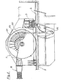
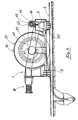
- the train emergency stop device comprises a wheeled frame, overally indicated at the reference number 1, which is provided with wheels 3 for displacement on the railroad rails 5, and with anti-raising pads 5 acting on the intrados 6 of the rail stem in order to balance the tilting moment occurring as the train impacts against the subject device.
- a pair of buffers indicated at 10, which are preloaded by an inert gas having a resilient type of characteristic curve; as shown, said buffers consist of a central or main body 11 which, at the bottom thereof, is provided with a buffer plate 12 and, at the rear thereof, defines a chamber 13 filled with a pressurized inert gas (see Figure 4).
- the central body 11 is tightly slidingly housed in the inside of a cylinder 14, closed by a bottom member 15 provided with an axial ridge or projection 16 susceptible to be tight coupled to the chamber 13.
- annular chamber 18 filled with oil, and adapted to preserve against wear the tightness gaskets 19 operating between said central body 11, cylinder 14 and axial projection 16.
- the oil chamber 18 is so shaped, at its end portion, to prevent said central body and bottom member 15 from impacting one against the other during the terminal portion of the stroke.
- the chamber 13 and the gas preloading pressure are so designed as to provide a resilient type of strain-deformation characteristic curve, having the desired stiffness.
- the chambers 13 communicate with one another through a coupling duct 20.
- the wheeled frame 1 rotatably supports a rotatable drum 21 which, preferably at an intermedie portion thereof, is formed with a seat or recess 22 for housing a high strength rope 23 which is wound on said drum by overlying coils, said rope 23 being anchored, at one end thereof, at 25, to the ground.
- Said ribbon brakes at their front ends, are anchored to a fixed point of the wheeled frame whereas, at the other ends thereof, after winding in the respective engaging seats, they are coupled to levers 40 of suitable linkages coupled to an adjustable torque limiting system adapted to operate after the starting of the carriage, as it will become more apparent hereinafter.
- a driving gear wheel 41 coaxial with the rotatable drum 21,there is provided a driving gear wheel 41, thereon is entrained a chain 42 also entrained on a gear wheel 43 keyed on a shaft 44 thereon there are arranged torque restraining or limiting devices 45 of known type.
- Each said torque restraining device 45 through a transmission chain 46, is coupled to the lever 40 articulated at a middle point thereof and coupled, at the other end thereof, to the respective ribbon brake.
- the braking system will transmit to the rotatable drum a constant braking torque, for the overall duration of its movement.
- the steel rope as above mentioned, is wound by overlaying coils: thus, during the operation, the ratio of the constant braking force diameter and the rope winding diameter will change between a maximum diameter and a minimum diameter; thus, a progressive stop action will be provided, with an increasing value from the starting time to the end time.
- the buffers will be deformed: according to the invention, the stroke and reaction force of said buffers are designed according to a characteristic curve able of causing the wheeled frame to be brought to the train speed in a gradual manner thereby preventing great inertial reaction forces from being generated at the start of the braking operation.
- the rope is un-wound and the rotatable drum rotated, in a gradual manner, since the rope is anchored with respect to the rotatable drum.
- the rotatable drum will not be engaged by the ribbon brakes as far as its rotating speed does not reach, from the rest status, the condition or speed corresponding to the impact speed of a train.
- the ribbon brakes are actuated for gradually braking and stopping the train.
Landscapes
- Engineering & Computer Science (AREA)
- Mechanical Engineering (AREA)
- Braking Arrangements (AREA)
- Train Traffic Observation, Control, And Security (AREA)
- Output Control And Ontrol Of Special Type Engine (AREA)
- Control Of Vehicles With Linear Motors And Vehicles That Are Magnetically Levitated (AREA)
Priority Applications (1)
| Application Number | Priority Date | Filing Date | Title |
|---|---|---|---|
| AT88830451T ATE71590T1 (de) | 1988-03-18 | 1988-10-26 | Notstop-prellbock, insbesondere fuer eisenbahnen. |
Applications Claiming Priority (2)
| Application Number | Priority Date | Filing Date | Title |
|---|---|---|---|
| IT8819857A IT1216159B (it) | 1988-03-18 | 1988-03-18 | Dispositivo di arresto d'emergenza, particolarmente studiato per convogli ferroviari. |
| IT1985788 | 1988-03-18 |
Publications (2)
| Publication Number | Publication Date |
|---|---|
| EP0332798A1 true EP0332798A1 (fr) | 1989-09-20 |
| EP0332798B1 EP0332798B1 (fr) | 1992-01-15 |
Family
ID=11161840
Family Applications (1)
| Application Number | Title | Priority Date | Filing Date |
|---|---|---|---|
| EP88830451A Expired - Lifetime EP0332798B1 (fr) | 1988-03-18 | 1988-10-26 | Butoir d'arrêt d'urgence spécialement conçu pour les chemins de fer |
Country Status (5)
| Country | Link |
|---|---|
| EP (1) | EP0332798B1 (fr) |
| AT (1) | ATE71590T1 (fr) |
| DE (1) | DE3867835D1 (fr) |
| ES (1) | ES2029349T3 (fr) |
| IT (1) | IT1216159B (fr) |
Cited By (2)
| Publication number | Priority date | Publication date | Assignee | Title |
|---|---|---|---|---|
| CN103273944A (zh) * | 2013-06-06 | 2013-09-04 | 枣庄矿业集团中兴建安工程有限公司 | 斜巷上变坡防跑车安全闭锁装置 |
| CN112810659A (zh) * | 2021-03-05 | 2021-05-18 | 华洋通信科技股份有限公司 | 一种适用于煤矿的物联网装置及使用方法 |
Families Citing this family (1)
| Publication number | Priority date | Publication date | Assignee | Title |
|---|---|---|---|---|
| DE10008781C2 (de) * | 2000-02-18 | 2002-05-29 | Schuesler Plan Ingenieurgesell | Anpralldämpfer |
Citations (6)
| Publication number | Priority date | Publication date | Assignee | Title |
|---|---|---|---|---|
| DE182373C (fr) * | ||||
| DE550164C (de) * | 1931-05-06 | 1932-05-09 | Schwaebische Huettenwerke Gmbh | Gleitender Bremsprellbock |
| DE807949C (de) * | 1950-03-26 | 1951-07-09 | Krauss Maffei Ag | Puffereinrichtung fuer Schienenfahrzeuge, insbesondere Huelsenpuffer |
| GB900220A (en) * | 1958-01-22 | 1962-07-04 | Meboe Ltd | Improvements in or relating to hydraulic buffers or drawgear |
| FR2073485A1 (fr) * | 1969-12-20 | 1971-10-01 | Bergens Mek Verksted | |
| FR2581608A1 (fr) * | 1985-05-13 | 1986-11-14 | Mecaneral | Heurtoir amortisseur pour le freinage de vehicules se deplacant sur une voie de guidage |
-
1988
- 1988-03-18 IT IT8819857A patent/IT1216159B/it active
- 1988-10-26 EP EP88830451A patent/EP0332798B1/fr not_active Expired - Lifetime
- 1988-10-26 ES ES198888830451T patent/ES2029349T3/es not_active Expired - Lifetime
- 1988-10-26 DE DE8888830451T patent/DE3867835D1/de not_active Expired - Fee Related
- 1988-10-26 AT AT88830451T patent/ATE71590T1/de not_active IP Right Cessation
Patent Citations (6)
| Publication number | Priority date | Publication date | Assignee | Title |
|---|---|---|---|---|
| DE182373C (fr) * | ||||
| DE550164C (de) * | 1931-05-06 | 1932-05-09 | Schwaebische Huettenwerke Gmbh | Gleitender Bremsprellbock |
| DE807949C (de) * | 1950-03-26 | 1951-07-09 | Krauss Maffei Ag | Puffereinrichtung fuer Schienenfahrzeuge, insbesondere Huelsenpuffer |
| GB900220A (en) * | 1958-01-22 | 1962-07-04 | Meboe Ltd | Improvements in or relating to hydraulic buffers or drawgear |
| FR2073485A1 (fr) * | 1969-12-20 | 1971-10-01 | Bergens Mek Verksted | |
| FR2581608A1 (fr) * | 1985-05-13 | 1986-11-14 | Mecaneral | Heurtoir amortisseur pour le freinage de vehicules se deplacant sur une voie de guidage |
Cited By (2)
| Publication number | Priority date | Publication date | Assignee | Title |
|---|---|---|---|---|
| CN103273944A (zh) * | 2013-06-06 | 2013-09-04 | 枣庄矿业集团中兴建安工程有限公司 | 斜巷上变坡防跑车安全闭锁装置 |
| CN112810659A (zh) * | 2021-03-05 | 2021-05-18 | 华洋通信科技股份有限公司 | 一种适用于煤矿的物联网装置及使用方法 |
Also Published As
| Publication number | Publication date |
|---|---|
| DE3867835D1 (de) | 1992-02-27 |
| IT8819857A0 (it) | 1988-03-18 |
| ES2029349T3 (es) | 1992-08-01 |
| IT1216159B (it) | 1990-02-22 |
| ATE71590T1 (de) | 1992-02-15 |
| EP0332798B1 (fr) | 1992-01-15 |
Similar Documents
| Publication | Publication Date | Title |
|---|---|---|
| KR101578232B1 (ko) | 가변 기어 비를 가진 동력 전달식 트랜스미션을 구비한 조합형 실린더 | |
| US6938735B1 (en) | Electromechanical wheel brake device | |
| US20030085082A1 (en) | Brake mechanism | |
| MX2007015323A (es) | Equipo de freno para fijar y frenar una jaula de ascensor y un metodo para fijar y frenar una instalacion de ascensor. | |
| AU2004224888A1 (en) | Brake for a lift | |
| EP0332798B1 (fr) | Butoir d'arrêt d'urgence spécialement conçu pour les chemins de fer | |
| JP4170761B2 (ja) | ディスクブレーキ | |
| US5487450A (en) | Braking apparatus and method for a rail-bound carriage of an inclined or vertical elevator | |
| FI73652C (fi) | Bromsanordning foer hiss. | |
| US6508336B1 (en) | Reduced drag wet disc brake assembly | |
| CN110329934B (zh) | 一种带盘式制动器的运输绞车 | |
| EP1549582B1 (fr) | Dispositif combine de guidage et de freinage de securite d'ascenseur | |
| EP0096553A1 (fr) | Assemblages de disque pour freins | |
| WO2004033354A1 (fr) | Dispositif de securite d'ascenseur | |
| JP2010510461A (ja) | 電気推進車両用キネマチックチェーン | |
| RU2235653C2 (ru) | Способ действия автоматического стояночного тормоза | |
| CN115092846A (zh) | 一种具备消声功能的制动器 | |
| US3255847A (en) | Disc brake | |
| NZ210991A (en) | Automatic wear adjuster for railway disc brakes:adjustable pivot points | |
| JP4214854B2 (ja) | 後側ドーリー装置のブレーキ装置 | |
| CA2996911C (fr) | Assemblage coussine de bout de wagon a friction | |
| KR20100031303A (ko) | 자동차용 전동브레이크 장치 | |
| CA2131493C (fr) | Cylindre de frein a rattrapage de jeu pour dispositif de freinage de vehicule de transport en commun sur rail | |
| KR101845336B1 (ko) | 제어효율 향상 및 수동 제동완해기능을 갖는 철도차량용 전기기계식 제동엑츄에이터 | |
| JP3477506B2 (ja) | オンオフ式トルクリミッタ |
Legal Events
| Date | Code | Title | Description |
|---|---|---|---|
| PUAI | Public reference made under article 153(3) epc to a published international application that has entered the european phase |
Free format text: ORIGINAL CODE: 0009012 |
|
| AK | Designated contracting states |
Kind code of ref document: A1 Designated state(s): AT BE CH DE ES FR GB LI NL SE |
|
| 17P | Request for examination filed |
Effective date: 19900213 |
|
| 17Q | First examination report despatched |
Effective date: 19910107 |
|
| GRAA | (expected) grant |
Free format text: ORIGINAL CODE: 0009210 |
|
| AK | Designated contracting states |
Kind code of ref document: B1 Designated state(s): AT BE CH DE ES FR GB LI NL SE |
|
| PG25 | Lapsed in a contracting state [announced via postgrant information from national office to epo] |
Ref country code: SE Effective date: 19920115 Ref country code: BE Effective date: 19920115 Ref country code: AT Effective date: 19920115 |
|
| REF | Corresponds to: |
Ref document number: 71590 Country of ref document: AT Date of ref document: 19920215 Kind code of ref document: T |
|
| PG25 | Lapsed in a contracting state [announced via postgrant information from national office to epo] |
Ref country code: NL Effective date: 19920215 |
|
| ET | Fr: translation filed | ||
| REF | Corresponds to: |
Ref document number: 3867835 Country of ref document: DE Date of ref document: 19920227 |
|
| NLV1 | Nl: lapsed or annulled due to failure to fulfill the requirements of art. 29p and 29m of the patents act | ||
| REG | Reference to a national code |
Ref country code: ES Ref legal event code: FG2A Ref document number: 2029349 Country of ref document: ES Kind code of ref document: T3 |
|
| PLBE | No opposition filed within time limit |
Free format text: ORIGINAL CODE: 0009261 |
|
| STAA | Information on the status of an ep patent application or granted ep patent |
Free format text: STATUS: NO OPPOSITION FILED WITHIN TIME LIMIT |
|
| 26N | No opposition filed | ||
| PGFP | Annual fee paid to national office [announced via postgrant information from national office to epo] |
Ref country code: ES Payment date: 20011029 Year of fee payment: 14 |
|
| PGFP | Annual fee paid to national office [announced via postgrant information from national office to epo] |
Ref country code: FR Payment date: 20011030 Year of fee payment: 14 |
|
| PGFP | Annual fee paid to national office [announced via postgrant information from national office to epo] |
Ref country code: GB Payment date: 20011031 Year of fee payment: 14 |
|
| PGFP | Annual fee paid to national office [announced via postgrant information from national office to epo] |
Ref country code: DE Payment date: 20011102 Year of fee payment: 14 |
|
| REG | Reference to a national code |
Ref country code: GB Ref legal event code: IF02 |
|
| PGFP | Annual fee paid to national office [announced via postgrant information from national office to epo] |
Ref country code: CH Payment date: 20020124 Year of fee payment: 14 |
|
| PG25 | Lapsed in a contracting state [announced via postgrant information from national office to epo] |
Ref country code: GB Free format text: LAPSE BECAUSE OF NON-PAYMENT OF DUE FEES Effective date: 20021026 |
|
| PG25 | Lapsed in a contracting state [announced via postgrant information from national office to epo] |
Ref country code: ES Free format text: LAPSE BECAUSE OF NON-PAYMENT OF DUE FEES Effective date: 20021027 |
|
| PG25 | Lapsed in a contracting state [announced via postgrant information from national office to epo] |
Ref country code: LI Free format text: LAPSE BECAUSE OF NON-PAYMENT OF DUE FEES Effective date: 20021031 Ref country code: CH Free format text: LAPSE BECAUSE OF NON-PAYMENT OF DUE FEES Effective date: 20021031 |
|
| PG25 | Lapsed in a contracting state [announced via postgrant information from national office to epo] |
Ref country code: DE Free format text: LAPSE BECAUSE OF NON-PAYMENT OF DUE FEES Effective date: 20030501 |
|
| REG | Reference to a national code |
Ref country code: CH Ref legal event code: PL |
|
| GBPC | Gb: european patent ceased through non-payment of renewal fee | ||
| PG25 | Lapsed in a contracting state [announced via postgrant information from national office to epo] |
Ref country code: FR Free format text: LAPSE BECAUSE OF NON-PAYMENT OF DUE FEES Effective date: 20030630 |
|
| REG | Reference to a national code |
Ref country code: FR Ref legal event code: ST |
|
| REG | Reference to a national code |
Ref country code: ES Ref legal event code: FD2A Effective date: 20031112 |