EP0332808A2 - Dispositif de contrôle des mesures axiales d'objets - Google Patents
Dispositif de contrôle des mesures axiales d'objets Download PDFInfo
- Publication number
- EP0332808A2 EP0332808A2 EP89100747A EP89100747A EP0332808A2 EP 0332808 A2 EP0332808 A2 EP 0332808A2 EP 89100747 A EP89100747 A EP 89100747A EP 89100747 A EP89100747 A EP 89100747A EP 0332808 A2 EP0332808 A2 EP 0332808A2
- Authority
- EP
- European Patent Office
- Prior art keywords
- clamping
- workpiece
- measuring devices
- workpieces
- center line
- Prior art date
- Legal status (The legal status is an assumption and is not a legal conclusion. Google has not performed a legal analysis and makes no representation as to the accuracy of the status listed.)
- Withdrawn
Links
Images
Classifications
-
- G—PHYSICS
- G01—MEASURING; TESTING
- G01B—MEASURING LENGTH, THICKNESS OR SIMILAR LINEAR DIMENSIONS; MEASURING ANGLES; MEASURING AREAS; MEASURING IRREGULARITIES OF SURFACES OR CONTOURS
- G01B5/00—Measuring arrangements characterised by the use of mechanical techniques
- G01B5/02—Measuring arrangements characterised by the use of mechanical techniques for measuring length, width or thickness
Definitions
- the invention also relates to a device for checking axial dimensions, such as, for example, total or partial lengths of workpieces, in particular shafts, axes, hubs and the like, with the features of the preamble of patent claim 1.
- a base body is designed as a base plate or base frame, on which the measuring devices, often consisting of guide elements or guide rod, length measuring probe and cranked probe tip, are mounted.
- a suitable probe tip must be selected or adapted depending on the distance of the individual measuring devices from the surface of the workpiece to be controlled by them.
- Particularly disadvantageous in such devices is the bridging of these distances between the measuring devices and the surfaces to be checked, if the workpiece to be measured, as is often the case with Transmission shafts, has large jumps in diameter, since the mounting position of the measuring devices usually depends on the largest diameter of the workpiece and therefore the probe tips must extend to the roots of the smallest diameters.
- such devices For receiving and holding the workpieces to be measured, such devices often contain guide strips on which quill holders or prisms are built, but which are completely independent of the structure of the measuring devices.
- the invention is therefore based on the object of providing a device for checking axial dimensions, such as total or partial lengths on workpieces, in particular on shafts, axes, near ends and the like, which avoids the disadvantages of the aforementioned devices and enables a much larger number of measuring points , whereby it should be able to be converted very quickly to different types of workpieces and also be suitable for picking up, holding, fixing and, if necessary, also clamping the workpiece to be inspected, and yet being compact, easy to handle and inexpensive.
- the device according to the invention can be seen in the fact that its base body is designed as a profile bar with a trapezoidal cross section, the trapezoidal surfaces of which are at a predeterminable distance from a workpiece center line of the workpiece to be checked has two symmetrically arranged clamping surfaces, preferably forming a right angle, into which T-slots are machined parallel to the workpiece center line and which can be equipped with clamping strips for receiving measuring and supporting devices and with structures for workpiece holding, workpiece fixing or workpiece clamping.
- the device according to the invention offers the advantageous possibility of a very high measuring point density, since a large number of measuring devices can be arranged either alternately or alternatively on the two clamping surfaces of the profiled bar which are at right angles to one another, the measuring devices being able to be right-handed or left-handed depending on the measuring task and workpiece design .
- the workpiece supporting support elements can be mounted on its clamping bars, so that a very simple and effective workpiece storage results.
- the profile rod according to the invention also offers the possibility of accommodating quill holders which are guided in the T-slots and can be fixed via T-slot nuts and which in turn can be equipped with inserts for holding, fixing or clamping the workpiece or workpieces. Due to the symmetrical arrangement of the clamping surfaces of the profile bar to each other is the advantageous possibility Given to use quill holders of a uniform design, and to use them either on the left or right of the workpiece in the corresponding T-slots, the quill axes being aligned with the workpiece center line when clamped.
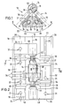
- a device 10 for checking the axial dimensions of a workpiece here for example a shaft 14 with a workpiece center line 16
- has an arbitrarily long profile bar 12 which has a first clamping surface 18 and a second clamping surface 20, which in the exemplary embodiment shown are below the workpiece center line 16 extend along this center line 16.
- the first clamping surface 18 and the second clamping surface 20 form one another, preferably a right angle 22.
- a first T-groove 24 is cut into the first clamping surface 18, the longitudinal axis 25 of which is arranged parallel to the workpiece center line 16;
- a second T-slot 26 is correspondingly cut into the second clamping surface 20, the longitudinal axis 27 of which likewise runs parallel to the workpiece center line 16.
- T-nuts 28 with which one first clamping bar 30 on the first clamping surface 18 and a second clamping bar 32 on the second clamping surface 20 can be fixed by screws 31, the clamping bars 30, 32 being attached or additionally attached to webs 29 in the T-slots 24, 26 along the longitudinal axes 25 , 27 of the T-grooves 24, 26 are feasible.
- the clamping bars 30, 32 can, depending on the shaft 14 to be measured, be equipped with measuring devices 34, which are only shown here in a simplified manner, for example with measuring probes parallel to the workpiece center line 16 and with support elements 36.
- FIG. 1 shows the fitting of the first clamping bar 30 with such a support element 36, which bears against the shaft 14 to be checked with a rounded contact surface 38.
- support elements 36 which support the workpiece on the end face with one or more rotatable circular disks which are rounded on the circumference.
- stops are provided in this case, which abut the weapon 14 on the end faces thereof and which can be fastened in the T-slots 24, 26 in a manner similar to the clamping bars 30, 32.
- FIG. 1 further shows the manner in which a clamping bar, shown here using the example of the second clamping bar 32, a measuring device 34 is arranged on the clamping bar (here 32).
- a clamping bar shown here using the example of the second clamping bar 32
- a measuring device 34 is arranged on the clamping bar (here 32).
- paragraphs 40 of the controlled shaft 14 are probed with a plurality of measuring devices 34, for example in order to determine the longitudinal extent between two such paragraphs 40.
- a further possibility of holding the shaft 14 to be checked is to center it in a first centering mandrel 42 and in a second centering mandrel 44 and in connection with a first quill holder 46 assigned to the first centering mandrel 42 and by means of a second one assigned to the second centering mandrel 44 Clamp and hold the quill holder 48.
- the sleeve holders 46, 48 preferably consist essentially of the sleeves receiving the centering mandrels 42, 44 with strip-like plates articulated thereon and are provided in the same way as the clamping bars 30, 32 with webs 29 and can be inserted into the T-slots 24, 26 through the T-nuts 28 can be fixed by means of screws 31.
- the sleeve holders 46, 48 are preferably of identical construction, they can be used both in the first T-slot 24 and in the second T-slot 26. In the clamped state, the centering mandrels 42, 44 in the sleeve holders 46, 48 are aligned with the workpiece center line 16.
- one of the quill holders serves as a stop for a clamping bar
- the second clamping bar 32 For the other clamping bar, which does not strike a quill holder, here: the first clamping bar 30, an additional stop piece 50 (FIG. 2) is provided, which, as shown in FIG. 2, passes through in the same way as the clamping bars 30, 32 and the quill holders 46, 48 a web 29 can be guided in the other T-slot 24 or 26 and can be locked by a T-slot nut 28.
- such measuring devices 34 or measuring probes are preferably used in which a length measuring device with integrated adjusting device transversely to the workpiece center line 16, ie parallel to the workpiece edge to be checked, is illustrated here using the example of paragraphs 40, can be arranged and the appropriate Nete probes or other deflection devices for scanning the surfaces to be checked.
- the type of workpiece support is first determined, which, as shown in the exemplary embodiment according to the invention, can be carried out via centering mandrels 42, 44 or support elements 36 arranged to prisms.
- the sleeve holders 46, 48 are suitable for holding or delivering centering mandrels or centering tips or clamping pieces in the same way, as is provided for the centering mandrels 42, 44 described above.
- the clamping bars 30, 32 are equipped with support elements 36 at the locations provided for this purpose.
- these end faces as supports if the end faces of the measuring devices 34 facing the workpiece 14 are designed accordingly.
- the arrangement of the measuring devices 34 takes place on the clamping bars 30, 32 which are then preferably brought to a stop on a quill holder 48 or on the stop piece 50 and clamped there.
- the shortest distance to be specified between the clamping surfaces 18, 20 of the profile bar 12 and the workpiece center line 16 is determined by the dimension between the clamping surfaces 18, 20 and the sensing plane of the measuring devices 34 and by the thickness of the clamping strips 30, 32.
- the measuring devices 34 shown it is also possible, in addition to the measuring devices 34 shown, to additionally mount such measuring devices on the clamping bars 30, 32 which are at right angles to a workpiece surface running parallel to the workpiece center line 16 are effective. This is particularly useful if the workpiece, for example a shaft, is moved about its axis of rotation during the measurement.
- the clamping bars 30, 32 are designed in this way and refer to one or more workpiece contours so that they can be easily replaced when changing over to another workpiece or another type of workpiece. It is up to the user to decide whether to replace the clamping bars with or without the removable measuring devices.
Landscapes
- Physics & Mathematics (AREA)
- General Physics & Mathematics (AREA)
- A Measuring Device Byusing Mechanical Method (AREA)
- Clamps And Clips (AREA)
Applications Claiming Priority (2)
| Application Number | Priority Date | Filing Date | Title |
|---|---|---|---|
| DE3808551A DE3808551A1 (de) | 1988-03-15 | 1988-03-15 | Vorrichtung zur kontrolle axialer masse von werkstuecken |
| DE3808551 | 1988-03-15 |
Publications (2)
| Publication Number | Publication Date |
|---|---|
| EP0332808A2 true EP0332808A2 (fr) | 1989-09-20 |
| EP0332808A3 EP0332808A3 (fr) | 1990-05-23 |
Family
ID=6349742
Family Applications (1)
| Application Number | Title | Priority Date | Filing Date |
|---|---|---|---|
| EP89100747A Withdrawn EP0332808A3 (fr) | 1988-03-15 | 1989-01-18 | Dispositif de contrôle des mesures axiales d'objets |
Country Status (4)
| Country | Link |
|---|---|
| US (1) | US4934062A (fr) |
| EP (1) | EP0332808A3 (fr) |
| JP (1) | JPH0216401A (fr) |
| DE (1) | DE3808551A1 (fr) |
Cited By (1)
| Publication number | Priority date | Publication date | Assignee | Title |
|---|---|---|---|---|
| WO1998021548A1 (fr) * | 1996-11-09 | 1998-05-22 | Ibb Technomes Gmbh | Dispositif de mesure |
Families Citing this family (1)
| Publication number | Priority date | Publication date | Assignee | Title |
|---|---|---|---|---|
| IT1266221B1 (it) * | 1993-01-21 | 1996-12-27 | Marposs Spa | Apparecchiatura per il controllo geometrico di pezzi a simmetria di rotazione |
Family Cites Families (5)
| Publication number | Priority date | Publication date | Assignee | Title |
|---|---|---|---|---|
| US2537704A (en) * | 1945-02-14 | 1951-01-09 | Theodore J Reinhart | Planer gauge |
| US3000101A (en) * | 1956-04-30 | 1961-09-19 | Giardino Loris | Electromechanical measuring apparatus |
| US3102344A (en) * | 1959-01-20 | 1963-09-03 | Martin A Herman | Simultaneous multi-check point gage |
| US4674193A (en) * | 1985-02-27 | 1987-06-23 | Wertepny Alexander W | Bench-center instrument |
| DE8610765U1 (de) * | 1986-04-19 | 1986-08-28 | Osthoff, Horst, 7141 Kleinbottwar | Meß- und Prüfvorrichtung |
-
1988
- 1988-03-15 DE DE3808551A patent/DE3808551A1/de not_active Withdrawn
-
1989
- 1989-01-18 EP EP89100747A patent/EP0332808A3/fr not_active Withdrawn
- 1989-03-14 JP JP1059844A patent/JPH0216401A/ja active Pending
- 1989-03-15 US US07/323,932 patent/US4934062A/en not_active Expired - Fee Related
Cited By (1)
| Publication number | Priority date | Publication date | Assignee | Title |
|---|---|---|---|---|
| WO1998021548A1 (fr) * | 1996-11-09 | 1998-05-22 | Ibb Technomes Gmbh | Dispositif de mesure |
Also Published As
| Publication number | Publication date |
|---|---|
| US4934062A (en) | 1990-06-19 |
| DE3808551A1 (de) | 1989-09-28 |
| JPH0216401A (ja) | 1990-01-19 |
| EP0332808A3 (fr) | 1990-05-23 |
Similar Documents
| Publication | Publication Date | Title |
|---|---|---|
| DE3919078C1 (fr) | ||
| DE3851443T2 (de) | System mit rotierenden paletten. | |
| EP0742081A2 (fr) | Etan universel de précision pour une machine-outil | |
| CH671356A5 (fr) | ||
| DE102019124746A1 (de) | Bearbeitungssystem | |
| EP0763709B1 (fr) | Machine de mesure de coordonnées à tête de mesure tournante autour de plusieurs axes | |
| DE4132655A1 (de) | Vorrichtung zum positionieren eines objektes, beispielsweise eines werkstueckes | |
| DE3737672A1 (de) | Haltevorrichtung | |
| EP0332808A2 (fr) | Dispositif de contrôle des mesures axiales d'objets | |
| DE4031490A1 (de) | Bohrungsmessgeraet | |
| EP0340867A2 (fr) | Méthode et dispositif pour monter une multipicité de guides d'ondes lumineuses dans une pince étau | |
| DE1797270C3 (de) | Einspannvorrichtung zur Halterung und Ausrichtung eines rotationssymmetrischen Bauteils | |
| DE29706615U1 (de) | Schneidwerkzeug, insbesondere in Form eines Seitenschneiders | |
| DE20208059U1 (de) | Werkzeuglagerungsvorrichtung, Werkzeugwechselvorrichtung und Lagerungseinheit | |
| EP1336815A2 (fr) | Dispositif de balayage pour la mesure des machines de production | |
| EP0204073B1 (fr) | Griffe maintenant une vis avec dispositif pour déterminer (mesurer, vérifier, travailler) la concentricité du filet et de la tige de la vis | |
| DE3808549A1 (de) | Vorrichtung zur kontrolle radialer masse von werkstuecken | |
| DE19910634C1 (de) | Vorrichtung zur Markierung von Positionen zur Anbringung formschlüssiger Verbindungselemente in Werkstücken | |
| DE3915893C2 (fr) | ||
| DE102021103905B4 (de) | Spanneinheit und Spannsystem mit wenigstens einer Spanneinheit | |
| DE1930999C3 (de) | Verbindungsmuffe | |
| DE2025604A1 (de) | Vorrichtung zum Spannen und Positio nieren verschiedenartiger Werkstucke | |
| DE196853C (fr) | ||
| DE3114786A1 (de) | Spannzange | |
| DE19648296C2 (de) | Voreingestellte Düse |
Legal Events
| Date | Code | Title | Description |
|---|---|---|---|
| PUAI | Public reference made under article 153(3) epc to a published international application that has entered the european phase |
Free format text: ORIGINAL CODE: 0009012 |
|
| AK | Designated contracting states |
Kind code of ref document: A2 Designated state(s): DE FR GB IT |
|
| PUAL | Search report despatched |
Free format text: ORIGINAL CODE: 0009013 |
|
| AK | Designated contracting states |
Kind code of ref document: A3 Designated state(s): DE FR GB IT |
|
| 17P | Request for examination filed |
Effective date: 19900414 |
|
| STAA | Information on the status of an ep patent application or granted ep patent |
Free format text: STATUS: THE APPLICATION HAS BEEN WITHDRAWN |
|
| 17Q | First examination report despatched |
Effective date: 19910611 |
|
| 18W | Application withdrawn |
Withdrawal date: 19910604 |