EP0340867A2 - Méthode et dispositif pour monter une multipicité de guides d'ondes lumineuses dans une pince étau - Google Patents
Méthode et dispositif pour monter une multipicité de guides d'ondes lumineuses dans une pince étau Download PDFInfo
- Publication number
- EP0340867A2 EP0340867A2 EP89201117A EP89201117A EP0340867A2 EP 0340867 A2 EP0340867 A2 EP 0340867A2 EP 89201117 A EP89201117 A EP 89201117A EP 89201117 A EP89201117 A EP 89201117A EP 0340867 A2 EP0340867 A2 EP 0340867A2
- Authority
- EP
- European Patent Office
- Prior art keywords
- clamping
- sorting
- clamp
- receiving channel
- forks
- Prior art date
- Legal status (The legal status is an assumption and is not a legal conclusion. Google has not performed a legal analysis and makes no representation as to the accuracy of the status listed.)
- Granted
Links
Images

Classifications
-
- G—PHYSICS
- G02—OPTICS
- G02B—OPTICAL ELEMENTS, SYSTEMS OR APPARATUS
- G02B6/00—Light guides; Structural details of arrangements comprising light guides and other optical elements, e.g. couplings
- G02B6/24—Coupling light guides
- G02B6/255—Splicing of light guides, e.g. by fusion or bonding
- G02B6/2555—Alignment or adjustment devices for aligning prior to splicing
-
- G—PHYSICS
- G02—OPTICS
- G02B—OPTICAL ELEMENTS, SYSTEMS OR APPARATUS
- G02B6/00—Light guides; Structural details of arrangements comprising light guides and other optical elements, e.g. couplings
- G02B6/24—Coupling light guides
- G02B6/36—Mechanical coupling means
- G02B6/3616—Holders, macro size fixtures for mechanically holding or positioning fibres, e.g. on an optical bench
-
- G—PHYSICS
- G02—OPTICS
- G02B—OPTICAL ELEMENTS, SYSTEMS OR APPARATUS
- G02B6/00—Light guides; Structural details of arrangements comprising light guides and other optical elements, e.g. couplings
- G02B6/24—Coupling light guides
- G02B6/255—Splicing of light guides, e.g. by fusion or bonding
- G02B6/2553—Splicing machines, e.g. optical fibre fusion splicer
Definitions
- the invention relates to a method for introducing a plurality of optical waveguides (LWL) into a clamping clamp, between the clamping jaws of which the optical waveguides are clamped next to one another in one plane.
- LWL optical waveguides
- EP-A-02 11 221 describes clamping clamps for firmly holding a plurality of optical waveguides (LWL) guided parallel to one another, in which the LWL are inserted in a first position on a multiple tool.
- the clamps can be moved lengthways and crossways on the multiple tool. They are moved into a second area for end face preparation and into a third area for making a welded joint. How the optical fibers are threaded into the clamps is not described.
- the invention is based on the object of specifying an easy-to-use method of the type mentioned at the outset, which also enables the relative position of the individual optical fibers to be maintained in the case of machining operations to be carried out on the fiber optics on different separate tools.
- the solution is achieved in that the clamping device is placed in a fixed position on a housing body between two sorting forks of the sorting device by means of form-locking elements in such a way that insertion channels of the sorting forks are aligned with a receiving channel of the clamping clamp, so that the optical fibers are then in the sorting forks and first by loosening its clamping jaws extended Receiving channel are inserted, that the fiber optic are pressed together by means of a sliding film inserted into the threading channels and / or the receiving channel, that then the clamping of the clamping jaws is effected and finally the clamping clamp together with the inserted optical fiber is removed from the sorting device.
- the threading aids are not part of the clamp, which can therefore be constructed very compactly with a small size.
- the fiber optic cable is inserted into the clamping clamp outside the actual processing tools, which are used to prepare and / or connect fiber optic groups. After the fiber optic is precisely and immovably juxtaposed by means of the clamp, it is removed together with the fiber it holds from the sorting device and can then be used in a defined position in any of the required subsequent devices.
- the fiber optic cables are preferably pressed against the stop base surfaces of the threading channels and / or the receiving channel by the sliding film. As a result, the individual fiber-optic cables are immediately positioned in a defined position relative to the sorting device.
- a sorting device which is advantageously suitable for carrying out the method according to the invention is thereby characterized in that it has a base body with two sorting forks opposite one another with free space, the threading channels of which are aligned with one another, and that between the sorting forks a clamping device can be fixed by means of interlocking elements with the receiving channel aligned with the threading channels.
- the clamping clamp can be inserted and removed in the sorting device in a simple and detachable manner via form-locking elements. It is preferably provided that the interlocking devices of the sorting device engage in interlocking devices of the clamping clamp, which are provided for fixing the clamping clamp on devices for producing and / or preparing a coupling connection of the optical fiber. Then the clamping clamp can be connected by means of simply provided interlocking elements with respectively associated interlocking elements of the sorting device and the subsequent tools.
- the positive locking elements are arranged on the sorting device, one of which engages in an associated bore of the clamp and the other in an elongated hole of the clamp, which runs in the direction of the connecting lines of the pins.
- Such form-locking elements are easy to manufacture and enable the clamp to be secured in an exact position.
- the removal of the clamping clamp that clamps a group of optical fibers out of the sorting device is facilitated in that one of the side walls forming the insertion channels can be folded down.
- the insertion and pressing of the fiber into the threading channels of the sorting fork and / or into the receiving channel of the clamping clamp is facilitated in that the sliding film is arranged on a sliding holder of the sorting device, which can be moved against the spring pressure in longitudinal bearings of the sorting device.
- FIGS. 2 to 4 explain how the optical fibers 3 are inserted into the receiving channel 1.
- the sorting device 7 has two sorting forks 8 and 9, into which mutually aligned threading channels 10 and 11 are introduced.
- the clamping clamp 2 which is inserted in the direction of the arrow 12, fits into the space between the sorting forks.
- the web 13 engages positively in the groove 14 of the clamp 2, which is thereby also secured against lateral displacement.
- the wall of the counter system 6 of the clamping clamp 2 is then aligned with the corresponding surfaces of the threading channels 10 and 11.
- the fiber optic cables 3 are inserted continuously into the threading channels 10 and 11 and pressed against the bottom surfaces 14 and 15 in the direction of the arrow 12 by means of the sliding film 16.
- the fiber optic cables extend in the area of the open receiving channel 1 of the clamping clamp 2 in parallel and adjoining one another.
- the clamping clamp 2 together with the fiber optic cable 3 held is removed from the sorting device 7 counter to the direction of the arrow 12.
- the clear width of the threading channels 10 and 11 is slightly larger than the diameter of the fiber optic cable 3.
- the threading channels can have soft-elastic constricted sections which cause the fiber optic cable 3 to be weakly clamped.
- the sliding film is slightly thinner than the width of the threading channels.
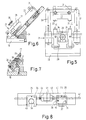
- FIGS. 5 to 7 show a further embodiment of a sorting device according to the invention, which is constructed as a compact and easy-to-use device and is therefore particularly suitable for frequently repeated work processes.
- a linear guide device 32, 33 for actuating the sliding film 22 is fixedly arranged, which the LWL with its projecting sections 23 and 24 only in the area of the threading channels 25 (FIG. 6) of the sorting forks 19 and 20 should push.
- a wall part 27 can be folded down around the swivel joint 28 against the holding force exerted by a permanent magnet 29 (FIG. 7) on the armature designed as a screw 30.
- the sliding film 22 is fastened to a holder 31, which can be guided by means of the linear guide devices 32 and 33 against the restoring force of the spring 34 in the direction of the sorting forks 19 and 20, as a result of which the sliding film is introduced into the threading channels 25 of the sorting forks 19 and 20 and press the previously inserted fiber optic cable.
- the clamping clamp 26 consists of two articulated clamping jaws 34 and 35, which can be moved relative to one another by means of the adjusting screw 36 for clamping the optical fibers introduced.
- the clamping jaw 25 resting on the sorting device 21 can be seen in FIG. It has a bore 37 and an elongated hole 38 as form-locking devices, in which associated pins (not shown) of the sorting device 21 engage.
- Similar pins 39 and 40 can be seen in FIG. 8 as positive-locking elements of a schematically indicated welding device, with which similar groups of optical fibers held along the path 42 and held by two clamping clamps 26 are to be welded to one another at the location of the dashed line 41.
- the fine alignment of the optical fibers protruding from the clamping clamps 26 and freed from the coating there is carried out by means of conventional sorting combs 43 and 44.
- the axial alignment and opposing of the two groups of optical fibers is achieved by the positive fixing of the clamping clamps 26 in recesses 43 and 44 of the welding device guaranteed.
- the method according to the invention and the sorting devices suitable therefor are suitable for planarizing a loose group of individual optical fibers. Likewise, however, flat ribbon groups of optical fibers already glued to one another in one plane can be fixed in a defined position in a clamp.
Landscapes
- Physics & Mathematics (AREA)
- General Physics & Mathematics (AREA)
- Optics & Photonics (AREA)
- Engineering & Computer Science (AREA)
- Plasma & Fusion (AREA)
- Mechanical Coupling Of Light Guides (AREA)
- Light Guides In General And Applications Therefor (AREA)
Applications Claiming Priority (2)
| Application Number | Priority Date | Filing Date | Title |
|---|---|---|---|
| DE3815459A DE3815459A1 (de) | 1988-05-06 | 1988-05-06 | Verfahren und vorrichtung zum einbringen einer mehrzahl von lichtwellenleitern in eine klemmzwinge |
| DE3815459 | 1988-05-06 |
Publications (3)
| Publication Number | Publication Date |
|---|---|
| EP0340867A2 true EP0340867A2 (fr) | 1989-11-08 |
| EP0340867A3 EP0340867A3 (en) | 1990-08-29 |
| EP0340867B1 EP0340867B1 (fr) | 1994-04-06 |
Family
ID=6353782
Family Applications (1)
| Application Number | Title | Priority Date | Filing Date |
|---|---|---|---|
| EP89201117A Expired - Lifetime EP0340867B1 (fr) | 1988-05-06 | 1989-05-01 | Méthode et dispositif pour monter une multipicité de guides d'ondes lumineuses dans une pince étau |
Country Status (4)
| Country | Link |
|---|---|
| US (1) | US5020874A (fr) |
| EP (1) | EP0340867B1 (fr) |
| JP (1) | JP2566008B2 (fr) |
| DE (2) | DE3815459A1 (fr) |
Cited By (3)
| Publication number | Priority date | Publication date | Assignee | Title |
|---|---|---|---|---|
| EP0475474A1 (fr) * | 1990-08-10 | 1992-03-18 | Philips Patentverwaltung GmbH | Dispositif pour le soudage de deux groupes de fibres optiques |
| FR2698452A1 (fr) * | 1992-11-25 | 1994-05-27 | Mars Actel | Dispositif de positionnement et de retenue en nappe de fibres optiques. |
| WO2000008497A3 (fr) * | 1998-08-06 | 2000-09-08 | Siemens Ag | Dispositif pour fixer de maniere temporaire des extremites de fibres optiques, dans une position definie |
Families Citing this family (6)
| Publication number | Priority date | Publication date | Assignee | Title |
|---|---|---|---|---|
| DE4006799A1 (de) * | 1990-03-03 | 1991-09-05 | Philips Patentverwaltung | Verfahren zur herstellung einer schweissverbindungsstelle zwischen zwei gruppen von lichtwellenleitern und vorrichtung zur ausuebung des verfahrens |
| USD334734S (en) | 1990-09-06 | 1993-04-13 | Reliance Comm/Tec Corporation | Optical fiber splicer |
| NL9100424A (nl) * | 1991-03-08 | 1992-10-01 | Nederland Ptt | Werkwijze voor het positioneren en fixeren van optische vezels in een optische vezelrij en een koppelinrichting voorzien van een dergelijke vezelrij. |
| IL97562A0 (en) * | 1991-03-15 | 1992-06-21 | Scitex Corp Ltd | Assembly of elongated elements,particularly a fibre optic head,and a method of making same |
| KR100492094B1 (ko) * | 1998-09-29 | 2005-08-02 | 삼성전자주식회사 | 광섬유블록 및 평면광도파로소자의 고정장치 |
| DE19852345A1 (de) * | 1998-11-13 | 2000-05-18 | Daimler Chrysler Ag | Vorrichtung und Verfahren zur Applikation von Lichtleitfasern |
Family Cites Families (6)
| Publication number | Priority date | Publication date | Assignee | Title |
|---|---|---|---|---|
| DE3149466C2 (de) * | 1981-12-14 | 1985-02-28 | ANT Nachrichtentechnik GmbH, 7150 Backnang | Vorrichtung zum Positionieren von Lichtleitfasern in V-Nuten |
| DE3328052A1 (de) * | 1983-08-03 | 1985-02-21 | Siemens AG, 1000 Berlin und 8000 München | Montagegeraet fuer mehrfachverbinder fuer lichtwellenleiter |
| US4717233A (en) * | 1983-12-15 | 1988-01-05 | Trw Inc. | Optical fiber splice system |
| JPS623208A (ja) * | 1985-06-28 | 1987-01-09 | Sumitomo Electric Ind Ltd | 光フアイバの接続方法 |
| JPS6228718A (ja) * | 1985-07-29 | 1987-02-06 | インタ−ナショナル ビジネス マシ−ンズ コ−ポレ−ション | 液晶表示装置 |
| US4812010A (en) * | 1987-02-06 | 1989-03-14 | Sumitomo Electric Industries, Ltd. | Apparatus for arranging a plurality of coated optical fibers and collective fusion splicing method using the apparatus |
-
1988
- 1988-05-06 DE DE3815459A patent/DE3815459A1/de not_active Withdrawn
-
1989
- 1989-05-01 DE DE89201117T patent/DE58907376D1/de not_active Expired - Fee Related
- 1989-05-01 EP EP89201117A patent/EP0340867B1/fr not_active Expired - Lifetime
- 1989-05-04 US US07/347,592 patent/US5020874A/en not_active Expired - Fee Related
- 1989-05-06 JP JP1114002A patent/JP2566008B2/ja not_active Expired - Lifetime
Cited By (7)
| Publication number | Priority date | Publication date | Assignee | Title |
|---|---|---|---|---|
| EP0475474A1 (fr) * | 1990-08-10 | 1992-03-18 | Philips Patentverwaltung GmbH | Dispositif pour le soudage de deux groupes de fibres optiques |
| FR2698452A1 (fr) * | 1992-11-25 | 1994-05-27 | Mars Actel | Dispositif de positionnement et de retenue en nappe de fibres optiques. |
| EP0599724A1 (fr) * | 1992-11-25 | 1994-06-01 | Alcatel Cable Interface | Dispositif de positionnement et de retenue en nappe de fibres optiques |
| US5416882A (en) * | 1992-11-25 | 1995-05-16 | Mars Actel | Device for positioning and retaining optical fibers in a layer |
| WO2000008497A3 (fr) * | 1998-08-06 | 2000-09-08 | Siemens Ag | Dispositif pour fixer de maniere temporaire des extremites de fibres optiques, dans une position definie |
| US6438312B1 (en) | 1998-08-06 | 2002-08-20 | Siemens Aktiengesellschaft | Apparatus for temporarily fixing light waveguide ends in a defined position |
| AU753193B2 (en) * | 1998-08-06 | 2002-10-10 | Siemens Aktiengesellschaft | Device for temporarily fixing optical waveguide ends in a position-defined manner |
Also Published As
| Publication number | Publication date |
|---|---|
| JPH0213907A (ja) | 1990-01-18 |
| US5020874A (en) | 1991-06-04 |
| JP2566008B2 (ja) | 1996-12-25 |
| DE58907376D1 (de) | 1994-05-11 |
| EP0340867A3 (en) | 1990-08-29 |
| DE3815459A1 (de) | 1989-11-16 |
| EP0340867B1 (fr) | 1994-04-06 |
Similar Documents
| Publication | Publication Date | Title |
|---|---|---|
| DE2726913C3 (de) | Vorrichtung zum Verbinden zweier ummantelter Einzellichtleitfasern | |
| DE2518319C2 (de) | Loesbare Spleissverbindung fuer Lichtwellenleiterkabel | |
| DE2626907A1 (de) | Kupplung fuer optische fasern | |
| DE2363986C3 (fr) | ||
| DE4434202A1 (de) | Kabeldurchführungsleiste | |
| DE2826032C3 (de) | Lösbare Steckverbindung für Lichtleitfasern und zugehörige Montagelehre | |
| EP0340867B1 (fr) | Méthode et dispositif pour monter une multipicité de guides d'ondes lumineuses dans une pince étau | |
| DE2759002C3 (de) | Steckverbinder zur lösbaren Verbindung zweier Lichtwellenleiter-Kabel | |
| DE69313760T2 (de) | Verfahren und Vorrichtung zum schrägen Schneiden eines faseroptischen Bandkabels | |
| DE2824507C2 (de) | Steckvorrichtung zur elektromagnetischen Kopplung von optischen Faserleitern | |
| DE2522804A1 (de) | Koppelvorrichtung fuer lichtleitfasern und verfahren zur herstellung der koppelvorrichtung | |
| DE2530883B2 (de) | Verfahren zum Verbinden von Einzellichtwellenleitern | |
| DE3306502A1 (de) | Spleisstraeger fuer lichtwellenleiterspleisse | |
| EP0475474A1 (fr) | Dispositif pour le soudage de deux groupes de fibres optiques | |
| DE2703406A1 (de) | Verbindungsanordnung fuer koaxiale leitungen | |
| DE2527008C3 (de) | Mehrfachsteckvorrichtung für Einzellichtwellenleiter | |
| DE2840101A1 (de) | Loesbare verbindung, insbesondere steckverbindung, zur kopplung von mindestens zwei lichtwellenleitern | |
| DE2743562C3 (de) | Vorrichtung zum Verbinden zweier ummantelter Einzellichtleitfasern | |
| DE3338493A1 (de) | Verfahren zum spleissen von glasfaser-buendeladern und vorrichtung zur durchfuehrung des verfahrens | |
| EP1103010B1 (fr) | Dispositif pour fixer de maniere temporaire des extremites de fibres optiques, dans une position definie | |
| EP0275087A2 (fr) | Connecteur avec manchon entourant des fibres optiques | |
| DE2827685C2 (de) | Verbindungsvorrichtung für ein mehradriges optisches Kabel | |
| DE4006799A1 (de) | Verfahren zur herstellung einer schweissverbindungsstelle zwischen zwei gruppen von lichtwellenleitern und vorrichtung zur ausuebung des verfahrens | |
| DE3244689A1 (de) | Vorrichtung zur lagegenauen positionierung der lwl-faserenden von lwl-bauteilen | |
| DE2811137C2 (de) | Stecker für Lichtleitfasern mit V-Nut-Führung |
Legal Events
| Date | Code | Title | Description |
|---|---|---|---|
| PUAI | Public reference made under article 153(3) epc to a published international application that has entered the european phase |
Free format text: ORIGINAL CODE: 0009012 |
|
| AK | Designated contracting states |
Kind code of ref document: A2 Designated state(s): DE ES FR GB IT |
|
| RHK1 | Main classification (correction) |
Ipc: G02B 6/38 |
|
| PUAL | Search report despatched |
Free format text: ORIGINAL CODE: 0009013 |
|
| AK | Designated contracting states |
Kind code of ref document: A3 Designated state(s): DE ES FR GB IT |
|
| 17P | Request for examination filed |
Effective date: 19910225 |
|
| 17Q | First examination report despatched |
Effective date: 19930628 |
|
| GRAA | (expected) grant |
Free format text: ORIGINAL CODE: 0009210 |
|
| AK | Designated contracting states |
Kind code of ref document: B1 Designated state(s): DE ES FR GB IT |
|
| PG25 | Lapsed in a contracting state [announced via postgrant information from national office to epo] |
Ref country code: IT Free format text: LAPSE BECAUSE OF FAILURE TO SUBMIT A TRANSLATION OF THE DESCRIPTION OR TO PAY THE FEE WITHIN THE PRE;WARNING: LAPSES OF ITALIAN PATENTS WITH EFFECTIVE DATE BEFORE 2007 MAY HAVE OCCURRED AT ANY TIME BEFORE 2007. THE CORRECT EFFECTIVE DATE MAY BE DIFFERENT FROM THE ONE RECORDED.SCRIBED TIME-LIMIT Effective date: 19940406 Ref country code: ES Free format text: THE PATENT HAS BEEN ANNULLED BY A DECISION OF A NATIONAL AUTHORITY Effective date: 19940406 |
|
| REF | Corresponds to: |
Ref document number: 58907376 Country of ref document: DE Date of ref document: 19940511 |
|
| GBT | Gb: translation of ep patent filed (gb section 77(6)(a)/1977) |
Effective date: 19940630 |
|
| ET | Fr: translation filed | ||
| PLBE | No opposition filed within time limit |
Free format text: ORIGINAL CODE: 0009261 |
|
| STAA | Information on the status of an ep patent application or granted ep patent |
Free format text: STATUS: NO OPPOSITION FILED WITHIN TIME LIMIT |
|
| 26N | No opposition filed | ||
| REG | Reference to a national code |
Ref country code: FR Ref legal event code: CD |
|
| REG | Reference to a national code |
Ref country code: FR Ref legal event code: TP |
|
| REG | Reference to a national code |
Ref country code: GB Ref legal event code: 732E |
|
| PGFP | Annual fee paid to national office [announced via postgrant information from national office to epo] |
Ref country code: GB Payment date: 19990413 Year of fee payment: 11 |
|
| PGFP | Annual fee paid to national office [announced via postgrant information from national office to epo] |
Ref country code: FR Payment date: 19990419 Year of fee payment: 11 |
|
| PGFP | Annual fee paid to national office [announced via postgrant information from national office to epo] |
Ref country code: DE Payment date: 19990420 Year of fee payment: 11 |
|
| PG25 | Lapsed in a contracting state [announced via postgrant information from national office to epo] |
Ref country code: GB Free format text: LAPSE BECAUSE OF NON-PAYMENT OF DUE FEES Effective date: 20000501 |
|
| GBPC | Gb: european patent ceased through non-payment of renewal fee |
Effective date: 20000501 |
|
| PG25 | Lapsed in a contracting state [announced via postgrant information from national office to epo] |
Ref country code: FR Free format text: LAPSE BECAUSE OF NON-PAYMENT OF DUE FEES Effective date: 20010131 |
|
| PG25 | Lapsed in a contracting state [announced via postgrant information from national office to epo] |
Ref country code: DE Free format text: LAPSE BECAUSE OF NON-PAYMENT OF DUE FEES Effective date: 20010301 |
|
| REG | Reference to a national code |
Ref country code: FR Ref legal event code: ST |