EP0333108A2 - Direction assistée pour véhicule à moteur - Google Patents
Direction assistée pour véhicule à moteur Download PDFInfo
- Publication number
- EP0333108A2 EP0333108A2 EP89104435A EP89104435A EP0333108A2 EP 0333108 A2 EP0333108 A2 EP 0333108A2 EP 89104435 A EP89104435 A EP 89104435A EP 89104435 A EP89104435 A EP 89104435A EP 0333108 A2 EP0333108 A2 EP 0333108A2
- Authority
- EP
- European Patent Office
- Prior art keywords
- motor vehicle
- steering
- steering system
- travel
- road wheels
- Prior art date
- Legal status (The legal status is an assumption and is not a legal conclusion. Google has not performed a legal analysis and makes no representation as to the accuracy of the status listed.)
- Granted
Links
- 239000003981 vehicle Substances 0.000 claims abstract description 82
- 238000007514 turning Methods 0.000 claims abstract description 29
- 230000001419 dependent effect Effects 0.000 claims abstract description 7
- 230000008859 change Effects 0.000 claims description 6
- 230000001276 controlling effect Effects 0.000 claims 5
- 238000001514 detection method Methods 0.000 claims 2
- 230000007246 mechanism Effects 0.000 abstract description 12
- 230000006870 function Effects 0.000 description 10
- 230000007935 neutral effect Effects 0.000 description 8
- 230000009471 action Effects 0.000 description 6
- 230000035945 sensitivity Effects 0.000 description 6
- 238000010586 diagram Methods 0.000 description 4
- 230000007423 decrease Effects 0.000 description 2
- 238000000034 method Methods 0.000 description 2
- 230000008569 process Effects 0.000 description 2
- 230000028838 turning behavior Effects 0.000 description 2
- 230000001133 acceleration Effects 0.000 description 1
- 230000006399 behavior Effects 0.000 description 1
- 230000008901 benefit Effects 0.000 description 1
- 238000006073 displacement reaction Methods 0.000 description 1
- 230000000694 effects Effects 0.000 description 1
- 230000004044 response Effects 0.000 description 1
- 230000001052 transient effect Effects 0.000 description 1
Images


Classifications
-
- B—PERFORMING OPERATIONS; TRANSPORTING
- B62—LAND VEHICLES FOR TRAVELLING OTHERWISE THAN ON RAILS
- B62D—MOTOR VEHICLES; TRAILERS
- B62D5/00—Power-assisted or power-driven steering
- B62D5/001—Mechanical components or aspects of steer-by-wire systems, not otherwise provided for in this maingroup
- B62D5/005—Mechanical components or aspects of steer-by-wire systems, not otherwise provided for in this maingroup means for generating torque on steering wheel or input member, e.g. feedback
- B62D5/006—Mechanical components or aspects of steer-by-wire systems, not otherwise provided for in this maingroup means for generating torque on steering wheel or input member, e.g. feedback power actuated
-
- B—PERFORMING OPERATIONS; TRANSPORTING
- B62—LAND VEHICLES FOR TRAVELLING OTHERWISE THAN ON RAILS
- B62D—MOTOR VEHICLES; TRAILERS
- B62D5/00—Power-assisted or power-driven steering
- B62D5/001—Mechanical components or aspects of steer-by-wire systems, not otherwise provided for in this maingroup
-
- B—PERFORMING OPERATIONS; TRANSPORTING
- B62—LAND VEHICLES FOR TRAVELLING OTHERWISE THAN ON RAILS
- B62D—MOTOR VEHICLES; TRAILERS
- B62D6/00—Arrangements for automatically controlling steering depending on driving conditions sensed and responded to, e.g. control circuits
- B62D6/002—Arrangements for automatically controlling steering depending on driving conditions sensed and responded to, e.g. control circuits computing target steering angles for front or rear wheels
Definitions
- the present invention relates to a steering system for use in a motor vehicle.
- Conventional steering systems for motor vehicles or the like include mechanical components such as gears, links, and the like which operatively interconnect a steering wheel and steerable road wheels. Steering action of the steering wheel is transmitted via the mechanical components to the steerable road wheels to turn the road wheels through an angle dependent on a steering angle ⁇ s of the steering wheel.
- the steering angle ⁇ s represents a desired amount (or a desired angle) by which the motor vehicle is to be turned from a reference direction of the motor vehicle (i.e., a straight running direction of the motor vehicle). Therefore, where the steering angle ⁇ s is zero, the motor vehicle runs along a straight course without changing its direction of travel.
- the resultant direction R3 of travel of the motor vehicle 200 is angularly shifted 90° clockwise from the original direction R1 of travel.
- the steering angle ⁇ s varies as shown in FIG. 7B.
- the steering wheel is turned in one direction (to the right in FIG. 7B) from the neutral position.
- the steering wheel is turned in the opposite direction (to the left) back to the neutral position.
- the driver may apply, as one steering input, a steering angle ⁇ s as a basis for producing a turning angle ⁇ of a steerable road wheel (e.g., a front wheel turning angle ⁇ f), to the steering system.
- a steering angle ⁇ s as a basis for producing a turning angle ⁇ of a steerable road wheel (e.g., a front wheel turning angle ⁇ f), to the steering system.
- the behavior of the motor vehicle while it is making a turn is greatly affected by lateral motion (transverse motion) and yawing.
- the lateral acceleration of the motor vehicle, a yaw rate (yaw angular velocity) r, and the radius R of the turning circle are related to the turning angle ⁇ (here, the front wheel turning angle ⁇ f) and the vehicle speed V as follows: where l: the wheelbase, and Kf: the stability factor indicative of the response of the motor vehicle.
- the stability factor Kf is also varied as it is affected by the transient characteristics. Therefore, the driver is also required to turn the steering wheel while taking into account such a change in the stability factor Kf.
- a steering system for a motor vehicle having power steering means including an actuator for turning steerable road wheels of the motor vehicle, said steering system comprising: direction indicating means for indicating a desired direction of travel of the motor vehicle with respect to a reference direction of the motor vehicle; direction detecting means for detecting an actual direction of travel of the motor vehicle; and control means responsive to an output signal from said direction indicating means and an output signal from said direction detecting means for controlling said power steering means to eliminate a deviation between said desired direction and said actual direction based on said output signals.
- a steering system for a motor vehicle having power steering means including an actuator for turning steerable road wheels of the motor vehicle comprising: direction indicating means for indicating a desired direction of travel of the motor vehicle with respect to a reference direction of the motor vehicle; direction detecting means for detecting an actual direction of travel of the motor vehicle with respect to said reference direction; target turning angle determining means responsive to an output signal from said direction indicating means and an output signal from said direction detecting means for calculating a deviation between said desired direction and said actual direction based on said output signals, and for determining a target turning angle for the steerable road wheels dependent on said deviation; and control means responsive to an output signal from said target turning angle determining means for controlling said power steering means to turn said steerable road wheels up to said target turning angle.
- a steering system 10 for a motor vehicle has a steering wheel 11 (direction indicating means) fixedly mounted on the upper end of a steering shaft 12 rotatably supported on a vehicle body (not shown).
- the steering shaft 12 is mechanically separate from steerable road wheels (not shown), and an encoder 13 and a reactive force generator 14 (reactive force applying means) including an electric motor (not shown) are mounted on the lower end of the steering shaft 12.
- the encoder 13 and the reactive force generator 14 are electrically connected to a controller 14 (control means) comprising a microcomputer and other electronic devices.
- the encoder 13 detects the angular displacement of the steering shaft 12 and applies a signal indicative of a steering angle ⁇ s to the controller 15.
- the electric motor of the reactive force generator 14 is controlled by the controller 15, as described later on, to apply a steering reactive force T to the steering shaft 12, i.e., the steering wheel 11 as it is turned.
- the steering reactive force T is applied to the steering wheel 11 by the reactive force generator 14. Since the steering wheel 11 is mechanically disconnected from the steerable road wheels, as described above, a self-aligning torque generated by the steerable road wheels when they are turned is not imposed on the steering wheel 11. In addition, the steering wheel 11 is not biased to rotate in either direction. As a consequence, the steering wheel 11 tends to stay in whatever position it may have been stopped by the driver of the motor vehicle.
- the steering angle ⁇ s is regarded as being zero when the steerable road wheels (e.g., front road wheels) are directed in a straight running direction.
- a front wheel steering angle ⁇ f is varied dependent on a change in the steering angle ⁇ s, as described below, to control the direction of travel of the motor vehicle or its angle (i.e., yaw angle ⁇ ) so as to achieve a desired direction or angle.
- a speedometer 16 applies a signal indicative of a vehicle speed V to the controller 15.
- the yaw rate gyroscope 17 applies a signal representing a yaw rate r (yaw angular velocity r) of the motor vehicle to the controller 15.
- the power steering mechanism PS has an electric motor (not shown) for producing a steering force, and a gear mechanism (not shown) disposed between the electric motor and the steerable road wheels.
- the controller 15 energizes the electric motor of the power steering mechanism PS to turn the steerable road wheels.
- the controller 15 processes signals from the encoder 13, the speedometer 16, and the yaw rate gyroscope 17 according to a predetermined program, and controls the electric motor of the reactive force generator 14 to apply the steering reactive force to the steering wheel 11 and also controls the electric motor of the power steering mechanism PS to turn the steerable wheels.
- the power steering mechanism PS is disclosed in Japanese Patent Application No. 62-331084 (331084/1987) filed December 26, 1987 by the applicant.
- the controller 15, in particular, of the steering system 10 has functions as shown in FIG. 2.
- the steering angle ⁇ s of the steering wheel 11 is basically representative of a desired direction in which the motor vehicle should run, with respect to a reference direction of travel of the motor vehicle (i.e., the direction in which the motor vehicle runs at the time).
- the steering angle ⁇ s is multiplied by a gain constant K to determine a converted indicated angle K ⁇ s.
- the yaw rate r is integrated to determine the yaw angle ⁇ of the motor vehicle from time to time.
- the yaw angle ⁇ is multiplied by a gain constant Kn to determine a converted running angle Kn ⁇ of the motor vehicle with respect to the reference direction.
- the running angle Kn ⁇ subtracted from the indicated angle K ⁇ s to calcu late a deviation ⁇ e therebetween.
- the deviation ⁇ e is multiplied by a gain constant Ks to determine a target turning angle Ks ⁇ e for the steerable road wheels.
- the gain constant Ks for obtaining the target turning angle Ks ⁇ e is a function of the vehicle speed V as described later on, the gain constant Ks varies with the vehicle speed V. If the vehicle speed V is constant, then the gain constant Ks is also constant, and the target turning angle Ks ⁇ is proportional to the deviation ⁇ e.
- the steerable road wheels are turned up to the target turning angle Ks ⁇ e by the power steering mechanism PS to cause the motor vehicle to make a turn.
- the turning motion of the motor vehicle varies the yaw rate r and also the converted running angle Kn ⁇ of the motor vehicle which has been calculated by the aforesaid integrating and multiplying process. In this manner, the steerable road wheels are turned until the running angle Kn ⁇ reaches the indicated angle K ⁇ s while feeding back the converted running angle Kn ⁇ from time to time.
- the steering reactive force T is applied to the steering wheel 11 by the reactive force generator 14.
- the steering reactive force T is basically of such a characteristic that it increases as the deviation ⁇ e increases.
- the steering reactive force T also increases as the vehicle speed V increases, as described later.
- the steerable road wheels are continuously turned transitionally with a characteristic dependent on the deviation ⁇ e, until finally the converted running angle Kn ⁇ of the motor vehicle reaches the indicated angle K ⁇ s. Even if the turning behavior of the motor vehicle is temporarily affected by a disturbance such as a lateral wind or the like, the final running angle Kn ⁇ of the motor vehicle is reliably achieved. Therefore, the running angle Kn ⁇ of the motor vehicle can reach the indicated angle K ⁇ s simply by turning the steering wheel 11 to give the desired indicated angle K ⁇ ⁇ s. As a consequence, the desired vehicle running angle K ⁇ s can be attained through relatively simple steering action.
- the steering angle ⁇ s varies as illustrated in FIG. 6C.
- the lanes can be changed only by a steering action effected on one side of a temporary neutral position, and hence it is not necessary to effect a steering action on both sides of the neutral position as with the conventional steering system as shown in FIG. 6B.
- the steering angle ⁇ s varies as shown in FIG. 7C.
- the steering wheel 11 is kept in the position to which it has been turned, and does not need to be returned to the neutral position as with the conventional steering system as shown in FIG. 7B.
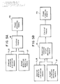
- FIGS. 5A and 5B illustrate functional blocks of the steering system 10.
- the target turning angle Ks ⁇ e is determined on the basis of the deviation ⁇ e.
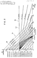
- All of the gain constants K, Kn, Ks, and Kp are functions of the vehicle speed V, and vary with the vehicle speed V.
- the lefthand side ( ⁇ e/ ⁇ s) of the equation (4′) indicates a normalized deviation or normalized input Nd
- the term ⁇ / ⁇ s on the righthand side indicates a normalized output No.
- the lefthand side (- ⁇ e/ ⁇ s) of the equation (4′) represents the sensitivity of the deviation ⁇ e to the steering angle ⁇ s
- the term ⁇ / ⁇ s on the righthand side represents the sensitivity of the yaw angle ⁇ to the steering angle ⁇ s.
- K 1 i.e., it is constant regardless of the vehicle speed V;
- the gain Kn for the yaw angle ⁇ increases in proportion to the vehicle speed V. Therefore, the higher the vehicle speed V, the higher the sensitivity with which the yaw angle ⁇ is detected. As a result, the rate of final change of the yaw angle ⁇ with respect to a unit steering angle is smaller as the vehicle speed V is higher.
- the gain constants K, Kn Both decrease in inverse proportion to the vehicle speed V.
- the gain constant K this decreases in inverse proportion to the vehicle speed V;
- K 1 i.e., it is constant irrespective of the vehicle speed V.
- the gain K for the steering angle ⁇ s increases in proportion to the vehicle speed V. Consequently, the higher the vehicle speed V, the lower the sensitivity with which the steering angle ⁇ s is applied. As a result, the rate of final change of the yaw angle ⁇ with respect to a unit steering angle is smaller as the vehicle speed V is higher.
- the steering reactive force T basically increases as the deviation ⁇ e increases and also as the vehicle speed V increases.
- the latter function has such a characteristic that the gain constant Kp increases as the vehicle speed V goes higher. Therefore, when the vehicle speed V is in a low range, a medium range, and a high range, the steering reactive force T increases respectively along characteristic curves Ltl, Ltm, Lth, shown in FIG. 4 as the deviation ⁇ e increases. Since an adequate reactive force is applied to the steering wheel 11 dependent on the deviation ⁇ e and the vehicle speed V, the steering action of the steering wheel 11 is stabilized, giving the driver a good steering feeling.
- the gain constants K, Kn, Kp are basically functions of the vehicle speed V only. However, they may be functions of (i) a steering amount such as a steering speed of the steering wheel 11, the deviation ⁇ e, etc., or (ii) a vehicle running condition such as the speed of a lateral wind applied to the motor vehicle, etc., or their combination.
- the present invention is applicable also the a steering system for a motor vehicle having steerable front and rear road wheels.
- a geomagnetism sensor may be employed instead of the yaw rate sensor 17 as means for detecting the actual direction of travel of the motor vehicle. Where such a geomagnetism sensor is used, the northward direction is used as an absolute reference direction.
Landscapes
- Engineering & Computer Science (AREA)
- Chemical & Material Sciences (AREA)
- Combustion & Propulsion (AREA)
- Transportation (AREA)
- Mechanical Engineering (AREA)
- Physics & Mathematics (AREA)
- Mathematical Physics (AREA)
- Steering Control In Accordance With Driving Conditions (AREA)
- Power Steering Mechanism (AREA)
Applications Claiming Priority (2)
| Application Number | Priority Date | Filing Date | Title |
|---|---|---|---|
| JP63061670A JPH0686222B2 (ja) | 1988-03-14 | 1988-03-14 | 操舵装置 |
| JP61670/88 | 1988-03-14 |
Publications (3)
| Publication Number | Publication Date |
|---|---|
| EP0333108A2 true EP0333108A2 (fr) | 1989-09-20 |
| EP0333108A3 EP0333108A3 (fr) | 1992-09-23 |
| EP0333108B1 EP0333108B1 (fr) | 1994-11-30 |
Family
ID=13177904
Family Applications (1)
| Application Number | Title | Priority Date | Filing Date |
|---|---|---|---|
| EP89104435A Expired - Lifetime EP0333108B1 (fr) | 1988-03-14 | 1989-03-13 | Direction assistée pour véhicule à moteur |
Country Status (6)
| Country | Link |
|---|---|
| US (1) | US4984646A (fr) |
| EP (1) | EP0333108B1 (fr) |
| JP (1) | JPH0686222B2 (fr) |
| AT (1) | ATE114563T1 (fr) |
| CA (1) | CA1315207C (fr) |
| DE (1) | DE68919491T2 (fr) |
Cited By (7)
| Publication number | Priority date | Publication date | Assignee | Title |
|---|---|---|---|---|
| EP0447626A3 (fr) * | 1990-03-23 | 1992-12-30 | Dr.Ing.h.c. F. Porsche Aktiengesellschaft | Déclencheur pour une direction cybernétique |
| EP0522924A1 (fr) * | 1991-07-12 | 1993-01-13 | Sextant Avionique | Actionneur rotatif apte à engendrer sur le volant de manoeuvre d'un système de commande, un couple résistant variable selon une loi adaptative |
| EP0557692A1 (fr) * | 1992-01-31 | 1993-09-01 | Robert Bosch Gmbh | Dispositif de commande de l'angle de braquage |
| RU2185988C1 (ru) * | 2000-10-30 | 2002-07-27 | Федеральный научно-производственный центр закрытое акционерное общество "Научно-производственный концерн (объединение) "ЭНЕРГИЯ" | Электропривод системы рулевого управления |
| RU2192984C2 (ru) * | 2000-09-11 | 2002-11-20 | Открытое акционерное общество "АВТОВАЗ" | Электропривод усилителя рулевого управления |
| EP1125826A3 (fr) * | 2000-02-11 | 2003-01-08 | Delphi Technologies, Inc. | Commande d'actuateurs de direction indépendants améliorant la stabilité et le freinage du véhicule |
| EP1447308A3 (fr) * | 2003-01-16 | 2004-12-15 | HONDA MOTOR CO., Ltd. | Direction de véhicule |
Families Citing this family (31)
| Publication number | Priority date | Publication date | Assignee | Title |
|---|---|---|---|---|
| US5067576A (en) * | 1990-08-15 | 1991-11-26 | Ford Motor Company | Variable effort steering system |
| JPH05105100A (ja) * | 1991-09-27 | 1993-04-27 | Honda Motor Co Ltd | 車両の操舵装置 |
| JP3098124B2 (ja) * | 1992-11-05 | 2000-10-16 | 本田技研工業株式会社 | 後輪転舵装置の制御方法 |
| DE4304664C2 (de) * | 1993-02-16 | 2000-04-06 | Daimler Chrysler Ag | Steuervorrichtung, insbesondere Lenkung für Kraftfahrzeuge |
| JP3172333B2 (ja) * | 1993-06-04 | 2001-06-04 | 本田技研工業株式会社 | 車輌用操舵装置 |
| JP3229074B2 (ja) * | 1993-06-04 | 2001-11-12 | 本田技研工業株式会社 | 車両用操舵装置 |
| JP3229077B2 (ja) * | 1993-06-29 | 2001-11-12 | 本田技研工業株式会社 | 車輌用操舵装置 |
| US5704446A (en) * | 1995-10-02 | 1998-01-06 | General Motors Corporation | Electric power steering control |
| US5668722A (en) * | 1995-10-02 | 1997-09-16 | General Motors Corporation | Electric power steering control |
| US5668721A (en) * | 1995-10-02 | 1997-09-16 | General Motors Corporation | Electric power steering motor control |
| US5719766A (en) * | 1995-10-02 | 1998-02-17 | General Motors Corporation | Electric power steering control |
| DE19546943C1 (de) * | 1995-12-15 | 1997-06-19 | Daimler Benz Ag | Lenkung für nicht spurgebundenes Fahrzeug |
| DE19600139C1 (de) * | 1996-01-04 | 1997-05-07 | Daimler Benz Ag | Bedienelementanordnung zur Steuerung des Lenkwinkels eines Kraftfahrzeuges |
| DE19625503C1 (de) * | 1996-06-26 | 1997-10-09 | Daimler Benz Ag | Lenkvorrichtung, insbesondere für ein Kraftfahrzeug |
| JPH10203393A (ja) * | 1997-01-21 | 1998-08-04 | Koyo Seiko Co Ltd | 車両用操舵装置 |
| DE19702313C1 (de) * | 1997-01-23 | 1998-04-02 | Daimler Benz Ag | Einrichtung zur Steuerung des Lenkwinkels eines Kraftfahrzeuges |
| JP3493568B2 (ja) * | 1997-02-12 | 2004-02-03 | 光洋精工株式会社 | 自動車の舵取装置 |
| US6141605A (en) * | 1999-06-25 | 2000-10-31 | Ford Global Technologies, Inc. | Determining the direction of travel of an automotive vehicle from yaw rate and relative steering wheel angle |
| US6581966B2 (en) * | 2001-01-05 | 2003-06-24 | Ford Global Technologies, Inc. | Twin axis steering wheel system |
| US20020180608A1 (en) | 2001-05-04 | 2002-12-05 | Sphericon Ltd. | Driver alertness monitoring system |
| US7083025B2 (en) * | 2002-06-03 | 2006-08-01 | Delphi Technologies, Inc. | Method for implementing vehicle stability enhancement reference models for active steer systems |
| JP4147836B2 (ja) | 2002-06-21 | 2008-09-10 | 株式会社ジェイテクト | 車両用操舵装置 |
| JP4398300B2 (ja) * | 2004-05-19 | 2010-01-13 | 本田技研工業株式会社 | 車両操舵装置 |
| JP4881631B2 (ja) * | 2006-02-28 | 2012-02-22 | 本田技研工業株式会社 | 車両操舵装置 |
| US7599774B2 (en) * | 2006-03-10 | 2009-10-06 | Gm Global Technology Operations, Inc. | Method and system for adaptively compensating closed-loop front-wheel steering control |
| US7933701B2 (en) * | 2006-12-28 | 2011-04-26 | Caterpillar Inc. | Closed-loop motion-control system using error to modify gain |
| US8131424B2 (en) * | 2008-01-16 | 2012-03-06 | GM Global Technology Operations LLC | Methods and systems for calculating yaw gain for use in controlling a vehicle |
| JP4486158B1 (ja) * | 2009-10-14 | 2010-06-23 | 株式会社近藤鐵工所 | 操舵装置 |
| JP5800194B2 (ja) * | 2011-11-08 | 2015-10-28 | 株式会社ジェイテクト | 車両用操舵装置及び荷役車両 |
| MX2017002988A (es) | 2014-09-09 | 2018-02-01 | Torvec Inc | Métodos y aparato para monitorear el nivel de alerta de una persona que utiliza un dispositivo portátil, y proporcionar una notificación. |
| CN108697391A (zh) | 2016-02-18 | 2018-10-23 | Curaegis科技公司 | 警觉性预测系统和方法 |
Family Cites Families (11)
| Publication number | Priority date | Publication date | Assignee | Title |
|---|---|---|---|---|
| US3011579A (en) * | 1959-01-08 | 1961-12-05 | Gen Motors Corp | Steering system |
| GB2090675B (en) * | 1978-01-19 | 1982-12-15 | Lely Nv C Van Der | A land vehicle having automatic steering control |
| JPS59111508A (ja) * | 1982-12-16 | 1984-06-27 | Agency Of Ind Science & Technol | 点追従方式による車両の自動誘導方法 |
| US4557342A (en) * | 1983-05-20 | 1985-12-10 | Trw Inc. | Hydraulic apparatus |
| JPS6067264A (ja) * | 1983-09-24 | 1985-04-17 | Jidosha Kiki Co Ltd | 動力舵取装置 |
| JPS60161255A (ja) * | 1984-01-31 | 1985-08-22 | Nissan Motor Co Ltd | 車両の補助操舵装置 |
| JPH0615340B2 (ja) * | 1985-12-27 | 1994-03-02 | 日産自動車株式会社 | 操舵反力制御装置 |
| JPH0667738B2 (ja) * | 1986-12-09 | 1994-08-31 | 東海テイ−ア−ルダブリユ−株式会社 | 電動機制動機能を備えた電動パワ−ステアリング装置 |
| JPS63180563A (ja) * | 1987-01-22 | 1988-07-25 | Honda Motor Co Ltd | 電動パワ−ステアリング装置 |
| US4865144A (en) * | 1988-04-29 | 1989-09-12 | Eaton Corporation | Power steering system having simulated torque sensor |
| US4860844A (en) * | 1988-04-29 | 1989-08-29 | Eaton Corporation | Power steering system |
-
1988
- 1988-03-14 JP JP63061670A patent/JPH0686222B2/ja not_active Expired - Fee Related
-
1989
- 1989-03-13 DE DE68919491T patent/DE68919491T2/de not_active Expired - Fee Related
- 1989-03-13 AT AT89104435T patent/ATE114563T1/de not_active IP Right Cessation
- 1989-03-13 EP EP89104435A patent/EP0333108B1/fr not_active Expired - Lifetime
- 1989-03-14 US US07/323,496 patent/US4984646A/en not_active Expired - Fee Related
- 1989-03-14 CA CA000593563A patent/CA1315207C/fr not_active Expired - Fee Related
Cited By (10)
| Publication number | Priority date | Publication date | Assignee | Title |
|---|---|---|---|---|
| EP0447626A3 (fr) * | 1990-03-23 | 1992-12-30 | Dr.Ing.h.c. F. Porsche Aktiengesellschaft | Déclencheur pour une direction cybernétique |
| EP0522924A1 (fr) * | 1991-07-12 | 1993-01-13 | Sextant Avionique | Actionneur rotatif apte à engendrer sur le volant de manoeuvre d'un système de commande, un couple résistant variable selon une loi adaptative |
| FR2678884A1 (fr) * | 1991-07-12 | 1993-01-15 | Sextant Avionique | Actionneur rotatif apte a engendrer sur le volant de manóoeuvre d'un systeme de commande, un couple resistant variable selon une loi adaptative. |
| EP0557692A1 (fr) * | 1992-01-31 | 1993-09-01 | Robert Bosch Gmbh | Dispositif de commande de l'angle de braquage |
| EP1125826A3 (fr) * | 2000-02-11 | 2003-01-08 | Delphi Technologies, Inc. | Commande d'actuateurs de direction indépendants améliorant la stabilité et le freinage du véhicule |
| US6719087B2 (en) | 2000-02-11 | 2004-04-13 | Delphi Technologies, Inc. | Control of independent steering actuators to improve vehicle stability and stopping |
| RU2192984C2 (ru) * | 2000-09-11 | 2002-11-20 | Открытое акционерное общество "АВТОВАЗ" | Электропривод усилителя рулевого управления |
| RU2185988C1 (ru) * | 2000-10-30 | 2002-07-27 | Федеральный научно-производственный центр закрытое акционерное общество "Научно-производственный концерн (объединение) "ЭНЕРГИЯ" | Электропривод системы рулевого управления |
| EP1447308A3 (fr) * | 2003-01-16 | 2004-12-15 | HONDA MOTOR CO., Ltd. | Direction de véhicule |
| US6918460B2 (en) | 2003-01-16 | 2005-07-19 | Honda Motor Co., Ltd. | Vehicle steering apparatus |
Also Published As
| Publication number | Publication date |
|---|---|
| JPH0686222B2 (ja) | 1994-11-02 |
| EP0333108A3 (fr) | 1992-09-23 |
| DE68919491D1 (de) | 1995-01-12 |
| ATE114563T1 (de) | 1994-12-15 |
| EP0333108B1 (fr) | 1994-11-30 |
| DE68919491T2 (de) | 1995-04-06 |
| CA1315207C (fr) | 1993-03-30 |
| JPH01233170A (ja) | 1989-09-18 |
| US4984646A (en) | 1991-01-15 |
Similar Documents
| Publication | Publication Date | Title |
|---|---|---|
| EP0333108A2 (fr) | Direction assistée pour véhicule à moteur | |
| US4794539A (en) | Propulsion control using steering angle and vehicle speed to determine tolerance range | |
| US4412594A (en) | Steering system for motor vehicles | |
| EP0198450B1 (fr) | Système de régulation de l'angle de glissement latéral et du gain en vitesse angulaire de lacet pour un véhicule | |
| US5019982A (en) | Method of controlling rear wheels of a four-wheel steering motor vehicles | |
| US4703822A (en) | Front and rear wheel steering device for a vehicle | |
| EP0379143B1 (fr) | Dispositif de braquage des roues arrières d'un véhicule | |
| US6209972B1 (en) | Braking force control system for automotive vehicle | |
| US20020042671A1 (en) | Motor vehicle with supplemental rear steering having open and closed loop modes | |
| US5684699A (en) | Travel characteristic control system for automotive vehicle | |
| US6345218B1 (en) | Vehicle steering control system based on vehicle body side slip angle | |
| US5684700A (en) | Adaptive steering control using vehicle slip angle and steering rate | |
| EP1892176A1 (fr) | Système de direction de véhicule | |
| US4869335A (en) | Four-wheel steering system of a motor vehicle | |
| US5184298A (en) | Rear wheel steering system for vehicle | |
| US5208751A (en) | Active four-wheel steering system for motor vehicles | |
| US20220097759A1 (en) | Method for determining a steering sensation of a steer-by-wire steering system | |
| EP1800994B1 (fr) | Module de commande de dispositif de conduite assistee electrique d' un vehicule dans lequel des roues braquees sont entrainees | |
| US5227974A (en) | Rear wheel turning system for four-wheel steered vehicle | |
| US4971173A (en) | Rear-wheel steering system of a motor vehicle | |
| US5515275A (en) | Control system for steering a road vehicle having both front-wheel steering and rear wheel steering | |
| DE68926064T2 (de) | Fahrzeug-Gleitwinkelüberwachungssystem | |
| US4958698A (en) | Method for steering a motor vehicle | |
| US5506770A (en) | Directional stability controller | |
| GB2216080A (en) | Method and device for rear wheel steering system of automotive vehicle |
Legal Events
| Date | Code | Title | Description |
|---|---|---|---|
| PUAI | Public reference made under article 153(3) epc to a published international application that has entered the european phase |
Free format text: ORIGINAL CODE: 0009012 |
|
| AK | Designated contracting states |
Kind code of ref document: A2 Designated state(s): AT CH DE FR GB IT LI SE |
|
| PUAL | Search report despatched |
Free format text: ORIGINAL CODE: 0009013 |
|
| AK | Designated contracting states |
Kind code of ref document: A3 Designated state(s): AT CH DE FR GB IT LI SE |
|
| 17P | Request for examination filed |
Effective date: 19921126 |
|
| 17Q | First examination report despatched |
Effective date: 19930810 |
|
| GRAA | (expected) grant |
Free format text: ORIGINAL CODE: 0009210 |
|
| AK | Designated contracting states |
Kind code of ref document: B1 Designated state(s): AT CH DE FR GB IT LI SE |
|
| PG25 | Lapsed in a contracting state [announced via postgrant information from national office to epo] |
Ref country code: IT Free format text: LAPSE BECAUSE OF FAILURE TO SUBMIT A TRANSLATION OF THE DESCRIPTION OR TO PAY THE FEE WITHIN THE PRE;WARNING: LAPSES OF ITALIAN PATENTS WITH EFFECTIVE DATE BEFORE 2007 MAY HAVE OCCURRED AT ANY TIME BEFORE 2007. THE CORRECT EFFECTIVE DATE MAY BE DIFFERENT FROM THE ONE RECORDED.SCRIBED TIME-LIMIT Effective date: 19941130 Ref country code: LI Effective date: 19941130 Ref country code: AT Effective date: 19941130 Ref country code: CH Effective date: 19941130 |
|
| REF | Corresponds to: |
Ref document number: 114563 Country of ref document: AT Date of ref document: 19941215 Kind code of ref document: T |
|
| REF | Corresponds to: |
Ref document number: 68919491 Country of ref document: DE Date of ref document: 19950112 |
|
| EAL | Se: european patent in force in sweden |
Ref document number: 89104435.6 |
|
| PGFP | Annual fee paid to national office [announced via postgrant information from national office to epo] |
Ref country code: SE Payment date: 19950228 Year of fee payment: 7 |
|
| PGFP | Annual fee paid to national office [announced via postgrant information from national office to epo] |
Ref country code: GB Payment date: 19950310 Year of fee payment: 7 |
|
| REG | Reference to a national code |
Ref country code: CH Ref legal event code: PL |
|
| ET | Fr: translation filed | ||
| PGFP | Annual fee paid to national office [announced via postgrant information from national office to epo] |
Ref country code: FR Payment date: 19950328 Year of fee payment: 7 |
|
| PGFP | Annual fee paid to national office [announced via postgrant information from national office to epo] |
Ref country code: DE Payment date: 19950331 Year of fee payment: 7 |
|
| PLBE | No opposition filed within time limit |
Free format text: ORIGINAL CODE: 0009261 |
|
| STAA | Information on the status of an ep patent application or granted ep patent |
Free format text: STATUS: NO OPPOSITION FILED WITHIN TIME LIMIT |
|
| 26N | No opposition filed | ||
| PG25 | Lapsed in a contracting state [announced via postgrant information from national office to epo] |
Ref country code: GB Effective date: 19960313 |
|
| PG25 | Lapsed in a contracting state [announced via postgrant information from national office to epo] |
Ref country code: SE Effective date: 19960314 |
|
| GBPC | Gb: european patent ceased through non-payment of renewal fee |
Effective date: 19960313 |
|
| PG25 | Lapsed in a contracting state [announced via postgrant information from national office to epo] |
Ref country code: FR Effective date: 19961129 |
|
| PG25 | Lapsed in a contracting state [announced via postgrant information from national office to epo] |
Ref country code: DE Effective date: 19961203 |
|
| EUG | Se: european patent has lapsed |
Ref document number: 89104435.6 |
|
| REG | Reference to a national code |
Ref country code: FR Ref legal event code: ST |