EP0333250A2 - Procédé pour déterminer la distribution de la magnétisation nucléaire et dispositif pour la mise en oeuvre du procédé - Google Patents
Procédé pour déterminer la distribution de la magnétisation nucléaire et dispositif pour la mise en oeuvre du procédé Download PDFInfo
- Publication number
- EP0333250A2 EP0333250A2 EP89200546A EP89200546A EP0333250A2 EP 0333250 A2 EP0333250 A2 EP 0333250A2 EP 89200546 A EP89200546 A EP 89200546A EP 89200546 A EP89200546 A EP 89200546A EP 0333250 A2 EP0333250 A2 EP 0333250A2
- Authority
- EP
- European Patent Office
- Prior art keywords
- frequency
- signal
- pulse
- larmor
- magnetic field
- Prior art date
- Legal status (The legal status is an assumption and is not a legal conclusion. Google has not performed a legal analysis and makes no representation as to the accuracy of the status listed.)
- Withdrawn
Links
Images
Classifications
-
- G—PHYSICS
- G01—MEASURING; TESTING
- G01R—MEASURING ELECTRIC VARIABLES; MEASURING MAGNETIC VARIABLES
- G01R33/00—Arrangements or instruments for measuring magnetic variables
- G01R33/20—Arrangements or instruments for measuring magnetic variables involving magnetic resonance
- G01R33/44—Arrangements or instruments for measuring magnetic variables involving magnetic resonance using nuclear magnetic resonance [NMR]
- G01R33/48—NMR imaging systems
- G01R33/4818—MR characterised by data acquisition along a specific k-space trajectory or by the temporal order of k-space coverage, e.g. centric or segmented coverage of k-space
- G01R33/482—MR characterised by data acquisition along a specific k-space trajectory or by the temporal order of k-space coverage, e.g. centric or segmented coverage of k-space using a Cartesian trajectory
-
- G—PHYSICS
- G01—MEASURING; TESTING
- G01R—MEASURING ELECTRIC VARIABLES; MEASURING MAGNETIC VARIABLES
- G01R33/00—Arrangements or instruments for measuring magnetic variables
- G01R33/20—Arrangements or instruments for measuring magnetic variables involving magnetic resonance
- G01R33/44—Arrangements or instruments for measuring magnetic variables involving magnetic resonance using nuclear magnetic resonance [NMR]
- G01R33/48—NMR imaging systems
- G01R33/483—NMR imaging systems with selection of signals or spectra from particular regions of the volume, e.g. in vivo spectroscopy
- G01R33/4838—NMR imaging systems with selection of signals or spectra from particular regions of the volume, e.g. in vivo spectroscopy using spatially selective suppression or saturation of MR signals
Definitions
- the invention relates to a method for determining the nuclear magnetization distribution, in which, in the presence of a homogeneous stationary magnetic field, several sequences act on an examination area, each sequence containing a high-frequency pulse, by means of which, in conjunction with a magnetic gradient field, the nuclear magnetization is located on both sides of a layer to be examined Areas is stimulated and possibly dephased, as well as an arrangement for performing this method.
- an amplitude-modulated high-frequency pulse is generated in that the oscillations of an oscillator are multiplied in a modulator in a manner known per se by an envelope signal which corresponds to the time course of the amplitude of the oscillator signal.
- Such a high-frequency pulse has the property that the thicker the area to be influenced, the greater the required high-frequency peak power. For this reason, relatively high peak performances are required for the known method.
- the object of the invention is to provide a method of the type mentioned at the outset which can manage with a lower high-frequency peak power.
- This object is achieved in that a signal is modulated onto a carrier whose frequency corresponds to the Larmor frequency in the middle of the layer to be examined, the frequency of which changes in a range which corresponds to the difference between this Larmor frequency and the Larmor frequencies in one of the ranges .
- a frequency-modulated high-frequency pulse is therefore used in the invention. It is known per se that a lower peak power is required to generate frequency-modulated high-frequency pulses than to generate amplitude-modulated high-frequency pulses for the same flip angle (EP-OS 85 200 644.4). While the duration of an amplitude-modulated high-frequency pulse is inversely proportional to its bandwidth and thus the thickness of the area to be excited by it, the duration of a frequency-modulated pulse can be chosen largely independently of the bandwidth; it can therefore be dimensioned so large that only a comparatively low high-frequency peak power is required.
- a frequency modulator is usually required to generate a frequency-modulated high-frequency pulse.
- Such a frequency modulator can - see FIG. 5 of EP-OS 85 200 644 - contain two modulators that act as multiplicative mixers, the other input of which is fed a signal that corresponds to the real part or the imaginary part of the frequency-modulated signal.
- the modulators present in the usual magnetic resonance examination devices only have a single multiplicative mixing stage with which one of the like frequency modulation can not be performed.
- the method according to the invention can be carried out with such a modulator. This is based on the following considerations:
- a frequency-modulated high-frequency pulse which influences the nuclear magnetization from the edge of this layer to the end of the reception or transmission range of the high-frequency coil in one of the two areas on either side of a layer to be examined, can be a complex function with regard to the lamor frequency in the middle of the layer to be examined represent.
- a complex high frequency pulse conjugated in this representation i.e. a pulse with the same amplitude, the same real part and an inverted imaginary part would now run through the negative frequencies, based on the frequency in the middle of the layer. This means that it would pass through an area in the opposite direction from the other edge of the layer to the other end of the transmission or reception area of the object.
- both high-frequency pulses can be applied to the examination area at the same time without influencing one another.
- the high-frequency pulse can be either a 90 ° high-frequency pulse or a 180 ° high-frequency pulse.
- the two areas are separated by a 90 ° high-frequency pulse excited on both sides of the layer while the layer itself is not excited.
- the nuclear magnetization in the regions on both sides of the layer must be dephased and then at least one non-selective high-frequency pulse must be generated which influences the nuclear magnetization in the entire high-frequency range.
- the nuclear magnetization outside the layer is already out of phase, only the layer itself makes a contribution to the nuclear magnetic resonance signals associated with this high-frequency pulse or these high-frequency pulses.
- the required dephasing in the areas on both sides of the layer can be achieved particularly easily by changing the frequency of the signal in such a way that the amount of the difference increases over time.
- the stimulation progresses in the areas from the inside out. Since a magnetic gradient field is present during the entire high-frequency pulse, in this embodiment the nuclear magnetization immediately on both sides of the layer is already dephased at the end of the high-frequency pulse, so that the magnetic gradient field can in this case be switched off at the end of the high-frequency pulse - or shortly thereafter.
- An arrangement for performing the method according to the invention which is provided with a magnet for generating a homogeneous stationary magnetic field, a gradient coil arrangement for generating magnetic fields running in the direction of the stationary magnetic field with gradients running in different directions, a high-frequency coil arrangement for generating a high-frequency, stationary magnetic field vertical Magnetic field and a high-frequency generator, which can be coupled to the high-frequency coil arrangement and contains a modulator which acts as a multiplicative mixing stage, is characterized in that a signal generator is provided which delivers a frequency-modulated signal and that in the modulator the vibrations of an oscillator which can be tuned to the Larmor frequency are combined with the Signal to be multiplied.
- a memory in which the signal is stored as a sequence of digital data words, and that the memory is coupled to an input of the modulator via a digital-to-analog converter.
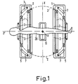
- the nuclear spin tomograph shown schematically in FIG. 1 contains an arrangement consisting of four coils 1 for generating a homogeneous stationary magnetic field which can be of the order of a few tenths to a few T. This field runs in the z direction of a Cartesian coordinate system.
- the coils 1 arranged concentrically to the z-axis can be arranged on a spherical surface 2.
- the patient 20 to be examined is located inside these coils.
- each coil 3 is preferably arranged on the same spherical surface. Furthermore, four coils 7 are provided, which generate a magnetic gradient field Gx, which also runs in the z direction, but whose gradient runs in the x direction.
- a magnetic gradient field Gy running in the z-direction with a gradient in the y-direction is generated by four coils 5, which can be identical to the coils 7, but which are arranged spatially offset from one another by 90 °. Only two of these four coils 5 are shown in FIG.
- each of the three coil arrangements 3, 5 and 7 for generating the magnetic gradient fields Gz, Gy and Gx is arranged symmetrically to the spherical surface 2, the field strength in the spherical center, which also forms the coordinate origin of the mentioned Cartesian x, y, z coordinate system, is only through determines the stationary homogeneous magnetic field of the coil arrangement 1.
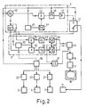
- the high-frequency coil is supplied with a high-frequency modulated current from a high-frequency generator during each high-frequency pulse. - Following one or more high-frequency pulses, the high-frequency coil 11 is used to receive the echo signals generated by nuclear magnetic resonance in the examination area. Instead, a separate high-frequency receiving coil could also be used.
- the high-frequency coil 11 is connected on the one hand to a high-frequency generator 4 and on the other hand to a high-frequency receiver 6 via a switching device 12.
- the high-frequency generator 4 contains a digitally controllable high-frequency oscillator 40, which has vibrations with a frequency equal to the Larmor frequency of those atomic nuclei whose spatial distribution in the layer is to be determined at the field strength generated by the coils 1.
- the output of the oscillator 40 is connected to an input of a mixer 43.
- the mixer 43 is supplied with a second input signal from a digital-to-analog converter 44, the input of which is connected to a digital memory 45. Controlled by a control device 15, a sequence of digital data words representing a frequency-modulated signal is read out of the memory 45.
- the multiplicative mixer 43 generates as the output signal a signal proportional to the product of the signals at its inputs; the frequency-modulated signal is thus modulated onto the carrier.
- the output signal of the mixer 43 is fed via a switch 46 controlled by the control device 15 to a high-frequency power amplifier 47, the output of which is connected to the switching device 12. This is also controlled by the control device 15.
- the receiver 6 contains a high-frequency amplifier 60, which is connected to the switching device and to which the echo signals induced in the high-frequency coil 11 and caused by nuclear magnetic resonance are supplied if the switching device 12 is controlled accordingly.
- the amplifier 60 has a mute input controlled by the control device 15, via which it can be blocked, so that the gain is practically zero.
- the output of amplifier 60 is connected to the first inputs of two multiplicative mixer stages 61 and 62, each of which supplies an output signal corresponding to the product of their input signals.
- a signal with the frequency of the oscillator 40 is fed to the second inputs of the mixer stage 61 and 62, with a phase shift of 90 ° between the signals at the two inputs. This phase shift is generated with the aid of a 90 ° phase shifter 48, the output of which is connected to the input of the mixer 62 and the input of which is connected to the input of the mixer 61 and to the output of the oscillator 40.
- the output signals of the mixer 61 and 62 are each via low-pass filters 63 and 64, which suppress the frequency supplied by the oscillator 40 and all frequencies above it and allow low-frequency components to pass through Analog-digital converter 65 and 66 supplied.
- This converts the analog signals of the circuit 61... 64 forming a quadrature demodulator into digital data words which are fed to a memory 14.
- the analog-to-digital converters 65 and 66 and the memory 14 receive their clock pulses from a clock pulse generator 16, which can be blocked or released by the control device 15 via a control line, so that only in a measurement interval defined by the control device 15 is that of the High-frequency coil 11 supplied, transposed into the low-frequency range signals can be converted into a sequence of digital data words and stored in the memory 14.
- the three coil arrangements 3, 5 and 7 are each supplied with a current by current generators 23, 25 and 27, the course of which can be controlled by the control unit 15.
- the data words or samples stored in the memory 14 are fed to a computer 17, which determines the spatial distribution of the nuclear magnetization in the layer under investigation and the determined distribution on a suitable display unit, e.g. a monitor 18.
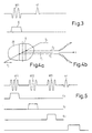
- HF1 (first line) denotes a frequency-modulated high-frequency pulse.
- a magnetic gradient field G is switched on (second line), for example in that the current generator 23 supplies a current for the gradient coil arrangement 3 during the high-frequency pulse.
- the high-frequency pulse HF1 which is a 90 ° high-frequency pulse, in conjunction with the magnetic gradient field G, causes that in the examination region 20 on both sides of a layer determined by the frequency of the oscillator 40, the nuclear magnetization is excited and dephased.
- the nuclear magnetization is excited in the entire examination area by a further high-frequency pulse HF following the first high-frequency pulse HF1, in which no magnetic gradient field is switched on.
- a further high-frequency pulse HF following the first high-frequency pulse HF1, in which no magnetic gradient field is switched on.
- the nuclear magnetization outside the layer is already dephased by the high-frequency pulse HF1
- only the nuclear magnetization within the layer makes a contribution to the nuclear magnetic resonance signal occurring after the high-frequency pulse HF.
- the high-frequency pulse HF which is preferably designed as a 90 ° high-frequency pulse
- two or more further high-frequency pulses can also be generated within a sequence.
- FIG. 4 a shows the examination object 20 and the layer S running perpendicular to the plane of the drawing, which results when the gradient of the magnetic gradient field runs in the horizontal direction.
- the Larmor frequency changes linearly from left to right in the examination area defined by object 20. It is f0 in the middle of layer S; on the left or right edge of the layer it is f1 or f2.
- a sequence of data words is stored in the memory 45 (FIG. 2), which, when the memory content is read out by the control unit 15 and processed by the digital-to-analog converter 44, results in a signal whose frequency is linear from a first value , the difference f2 - f0 corresponds to a second value which corresponds to the difference f4 - f0.
- the rate of change of the frequency is dimensioned such that the specified range is only run through once during the duration (e.g. 5 ms) of the high-frequency pulse HF1.
- the instantaneous frequency of the output signal of the digital-to-analog converter 44 is small compared to the Larmor frequency.
- This signal can therefore be stored in the memory 45 with relatively few data words, the envelope of this signal is expediently chosen as described in European patent application 85 200 644.
- This signal is mixed in the mixer 43 with the sinusoidal signal of the oscillator 40 tuned to the frequency f0.
- the output signal of the mixer 43 which is proportional to the product of these input signals, therefore contains a component whose frequency changes linearly from a value f2 to a value f.4 (see FIG. 4b) and a component whose frequency spacing to the same extent, but in opposite direction changes, as in the former component, ie from f1 to f3.
- the associated high-frequency pulse HF1 therefore has the result that the Larmor frequencies first appear in the two areas immediately adjacent to the layer and then in the areas further away in the high-frequency pulse HF1.
- the nuclear magnetization thereby excited in these areas is dephased by the fact that the magnetic gradient field G remains switched on beyond this excitation.
- the nuclear magnetization in the parts of the examination area located on both sides of the layer S is therefore out of phase when the magnetic gradient field G is switched off with the high-frequency pulse HF1 - or shortly thereafter if necessary.
- the method shown in Figure 5 is based on the one in J. Magn. Reson. 66 , pages 283 to 294 (1986), the so-called ISIS method, in which up to three 180 ° high-frequency pulses act on an examination area, the nuclear magnetization being inverted in one of three mutually perpendicular layers by each high-frequency pulse.
- the use of the frequency-modulated high-frequency pulses stimulates the nuclear magnetization on both sides of the respective layer, while it remains unchanged in the layer itself.
- the method comprises sequence sequences with eight sequences each.
- Each sequence contains up to three slice-selective frequency-modulated 180 ° high-frequency pulses HF1, HF2 and HF3, and always one non-selective high-frequency pulse HF, which is preferably a 90 ° pulse.
- the eight sequences in a sequence contain the three high-frequency pulses HF1 to HF3 in the eight possible combinations. One of the eight sequences therefore does not contain any of the three high-frequency pulses, while another contains all three high-frequency pulses.
- Each three of the sequences contain only one or two of the high-frequency pulses in different combinations.
- the only sequence of the sequence shown in FIG. 5 comprises only the high-frequency pulse HF1 (first line), which is linked to the magnetic gradient field Gx (second line) and the high-frequency pulse HF3 associated with the magnetic gradient field Gx (fourth line).
- the position of the second high-frequency pulse HF2 which does not occur in this sequence and the associated magnetic gradient field Gy (third line) is indicated by dashed lines in FIG.
- the pulse HF3 is followed by the further high-frequency pulse HF, which covers the entire Stimulates the examination area and generates a nuclear magnetic resonance signal that originates from the entire examination area. This nuclear magnetic resonance signal is sampled, ie the pulse generator 16 is released (cf. fifth line).
- Each of the high-frequency pulses HF1..HF3 inverts the nuclear magnetization on both sides of a layer which is perpendicular to the direction of the gradient associated with the high-frequency pulse.
- the nuclear magnetization is not inverted by any of the high-frequency pulses.
- four of the sequences have an inverting effect and the other four have a non-inverting effect. Therefore, if one adds the nuclear magnetic resonance signals generated in the eight sequences of a sequence sequence, only the mentioned cutting area makes a contribution, while the portion of the nuclear magnetic resonance signals originating from the other areas compensate each other.
- the high-frequency pulses HF1 and HF3 are each generated in the same way as described with reference to FIGS. 3 and 4a and b. However, their energy content is larger, so that there is a flip angle of 180 °. In this case, dephasing the nuclear magnetization is neither possible nor necessary; only the nuclear magnetization is inverted on both sides of a layer by the frequency-modulated 180 ° high-frequency pulses in this way.
Landscapes
- Physics & Mathematics (AREA)
- High Energy & Nuclear Physics (AREA)
- Condensed Matter Physics & Semiconductors (AREA)
- General Physics & Mathematics (AREA)
- Magnetic Resonance Imaging Apparatus (AREA)
Applications Claiming Priority (2)
| Application Number | Priority Date | Filing Date | Title |
|---|---|---|---|
| DE3808281 | 1988-03-12 | ||
| DE3808281A DE3808281A1 (de) | 1988-03-12 | 1988-03-12 | Verfahren zur bestimmung der kernmagnetisierungsverteilung und anordnung zur durchfuehrung des verfahrens |
Publications (2)
| Publication Number | Publication Date |
|---|---|
| EP0333250A2 true EP0333250A2 (fr) | 1989-09-20 |
| EP0333250A3 EP0333250A3 (fr) | 1990-12-27 |
Family
ID=6349563
Family Applications (1)
| Application Number | Title | Priority Date | Filing Date |
|---|---|---|---|
| EP19890200546 Withdrawn EP0333250A3 (fr) | 1988-03-12 | 1989-03-06 | Procédé pour déterminer la distribution de la magnétisation nucléaire et dispositif pour la mise en oeuvre du procédé |
Country Status (4)
| Country | Link |
|---|---|
| US (1) | US4939461A (fr) |
| EP (1) | EP0333250A3 (fr) |
| JP (1) | JPH027939A (fr) |
| DE (1) | DE3808281A1 (fr) |
Cited By (1)
| Publication number | Priority date | Publication date | Assignee | Title |
|---|---|---|---|---|
| US6714011B1 (en) | 1999-06-19 | 2004-03-30 | Koninklijke Philips Electronics N.V. | MR apparatus and gradient saturation method for suppressing MR signals from peripheral regions situated outside an isocenter |
Families Citing this family (1)
| Publication number | Priority date | Publication date | Assignee | Title |
|---|---|---|---|---|
| GB2253702B (en) * | 1991-03-12 | 1995-03-22 | Instrumentarium Corp | apparatus and method |
Family Cites Families (6)
| Publication number | Priority date | Publication date | Assignee | Title |
|---|---|---|---|---|
| US4021726A (en) * | 1974-09-11 | 1977-05-03 | National Research Development Corporation | Image formation using nuclear magnetic resonance |
| JPS58223048A (ja) * | 1982-06-21 | 1983-12-24 | Toshiba Corp | 磁気共鳴励起領域選択方法、および、該方法が実施し得る磁気共鳴イメージング装置 |
| US4695799A (en) * | 1985-06-18 | 1987-09-22 | General Electric Company | NMR magnetization inversion by non-linear adiabatic fast passage |
| US4843549A (en) * | 1986-02-21 | 1989-06-27 | U.S. Philips Corporation | Method of determining the spectral distribution of the nuclear magnetization in a limited volume, and device for performing the method |
| DE3631039A1 (de) * | 1986-09-12 | 1988-03-24 | Philips Patentverwaltung | Kernspintomographieverfahren und kernspintomograph zur durchfuehrung des verfahrens |
| IL84152A (en) * | 1987-10-12 | 1991-06-10 | Elscint Ltd | Magnetic resonance spectroscopic measurements of restricted volumes |
-
1988
- 1988-03-12 DE DE3808281A patent/DE3808281A1/de not_active Withdrawn
-
1989
- 1989-03-06 EP EP19890200546 patent/EP0333250A3/fr not_active Withdrawn
- 1989-03-09 JP JP1057689A patent/JPH027939A/ja active Pending
- 1989-03-10 US US07/321,492 patent/US4939461A/en not_active Expired - Fee Related
Cited By (1)
| Publication number | Priority date | Publication date | Assignee | Title |
|---|---|---|---|---|
| US6714011B1 (en) | 1999-06-19 | 2004-03-30 | Koninklijke Philips Electronics N.V. | MR apparatus and gradient saturation method for suppressing MR signals from peripheral regions situated outside an isocenter |
Also Published As
| Publication number | Publication date |
|---|---|
| DE3808281A1 (de) | 1989-09-21 |
| JPH027939A (ja) | 1990-01-11 |
| EP0333250A3 (fr) | 1990-12-27 |
| US4939461A (en) | 1990-07-03 |
Similar Documents
| Publication | Publication Date | Title |
|---|---|---|
| EP0642031B1 (fr) | Procédé pour la formation d'images par résonance magnétique et dispositif pour la mise en oeuvre du procédé | |
| EP0226247A2 (fr) | Procédé de tomographie à spin nucléaire et dispositif de mise en oeuvre de ce procédé | |
| EP0789251B1 (fr) | Procédé RM de détermination de l'inhomogénéité du champ magnétique dans la région d'examen et dispositif RM pour la mise en oeuvre du procédé | |
| EP0404248A2 (fr) | Procédé d'imagerie R.M.N. | |
| DE68918048T2 (de) | Kernspinresonanzverfahren und -anordnung. | |
| EP0412602B1 (fr) | Procédé de spectroscopie RMN et dispositif pour sa mise en oeuvre | |
| EP0259935B1 (fr) | Procédé de tomographie en spins nucléaires et tomographe en spins nucléaires pour la mise en oeuvre du procédé | |
| DE3739856A1 (de) | Kernresonanz-spektroskopieverfahren | |
| EP0357100A2 (fr) | Procédé tomographique à résonance nucléaire et tomographe à résonance nucléaire pour la mise en oeuvre de ce procédé | |
| EP0329240A2 (fr) | Procédé pour déterminer la distribution spectrale de la magnétisation nucléaire dans un volume limité et dispositif pour la mise en oeuvre du procédé | |
| EP0427343A2 (fr) | Procédé de tomographie à spin nucléaire pour la production d'images séparées de la graisse et de l'eau et dispositif pour la réalisation du procédé | |
| EP0233675B1 (fr) | Procédé pour déterminer la distribution spectrale de la magnétisation nucléaire dans un volume limité et dispositif pour la mise en oeuvre du procédé | |
| EP0430322A2 (fr) | Procédé de tomographie à spin nucléaire et tomographe à spin nucléaire pour la réalisation du procédé | |
| EP0232945A2 (fr) | Procédé pour déterminer la distribution de la magnétisation nucléaire dans une couche de région d'examen et tomographe à spin nucléaire pour la mise en oeuvre du procédé | |
| EP0496447B1 (fr) | Procédé de spectroscopie RMN et dispositif de mise en oeuvre du procédé | |
| EP0392574A2 (fr) | Procédé pour la spectroscopie à résonance nucléaire localisée et dispositif pour son exécution | |
| DE3837317A1 (de) | Kernresonanzspektroskopieverfahren und anordnung zur durchfuehrung des verfahrens | |
| EP0478030B1 (fr) | Procédé pour la spectroscopie RMN à deux dimensions | |
| EP0261743A2 (fr) | Procédé pour déterminer la distribution spectrale de la magnétisation nucléaire dans un volume limité | |
| EP0333250A2 (fr) | Procédé pour déterminer la distribution de la magnétisation nucléaire et dispositif pour la mise en oeuvre du procédé | |
| EP0248469B1 (fr) | Procédé de tomographie dans des spins nucléaires | |
| DE3701849A1 (de) | Verfahren und vorrichtung fuer die kernspintomographie | |
| EP0307989A2 (fr) | Spectromètre à résonance magnétique nucléaire | |
| EP0300564A2 (fr) | Procédé d'analyse par résonance magnétique nucléaire | |
| EP0302550A2 (fr) | Procédé de spectroscopie RMN |
Legal Events
| Date | Code | Title | Description |
|---|---|---|---|
| PUAI | Public reference made under article 153(3) epc to a published international application that has entered the european phase |
Free format text: ORIGINAL CODE: 0009012 |
|
| AK | Designated contracting states |
Kind code of ref document: A2 Designated state(s): DE FR GB NL |
|
| PUAL | Search report despatched |
Free format text: ORIGINAL CODE: 0009013 |
|
| AK | Designated contracting states |
Kind code of ref document: A3 Designated state(s): DE FR GB NL |
|
| STAA | Information on the status of an ep patent application or granted ep patent |
Free format text: STATUS: THE APPLICATION IS DEEMED TO BE WITHDRAWN |
|
| 18D | Application deemed to be withdrawn |
Effective date: 19910628 |