EP0333261A2 - Méthode et installation pour la production d'énergie électrique et de gaz pour des synthèses chimiques au moyen d'oxydation dans des bains métalliques fondus - Google Patents
Méthode et installation pour la production d'énergie électrique et de gaz pour des synthèses chimiques au moyen d'oxydation dans des bains métalliques fondus Download PDFInfo
- Publication number
- EP0333261A2 EP0333261A2 EP89200598A EP89200598A EP0333261A2 EP 0333261 A2 EP0333261 A2 EP 0333261A2 EP 89200598 A EP89200598 A EP 89200598A EP 89200598 A EP89200598 A EP 89200598A EP 0333261 A2 EP0333261 A2 EP 0333261A2
- Authority
- EP
- European Patent Office
- Prior art keywords
- gas
- bath
- molten metal
- fuel
- electrical energy
- Prior art date
- Legal status (The legal status is an assumption and is not a legal conclusion. Google has not performed a legal analysis and makes no representation as to the accuracy of the status listed.)
- Withdrawn
Links
- 229910052751 metal Inorganic materials 0.000 title claims abstract description 68
- 239000002184 metal Substances 0.000 title claims abstract description 68
- 238000000034 method Methods 0.000 title claims abstract description 64
- 238000004519 manufacturing process Methods 0.000 title claims abstract description 25
- 238000003786 synthesis reaction Methods 0.000 title claims abstract description 19
- 238000007254 oxidation reaction Methods 0.000 title claims description 12
- 230000003647 oxidation Effects 0.000 title claims description 11
- 239000000446 fuel Substances 0.000 claims abstract description 46
- OKTJSMMVPCPJKN-UHFFFAOYSA-N Carbon Chemical compound [C] OKTJSMMVPCPJKN-UHFFFAOYSA-N 0.000 claims abstract description 25
- 229910052799 carbon Inorganic materials 0.000 claims abstract description 25
- 239000007784 solid electrolyte Substances 0.000 claims abstract description 21
- 239000012535 impurity Substances 0.000 claims abstract description 7
- 239000007789 gas Substances 0.000 claims description 63
- 238000006243 chemical reaction Methods 0.000 claims description 43
- XEEYBQQBJWHFJM-UHFFFAOYSA-N Iron Chemical compound [Fe] XEEYBQQBJWHFJM-UHFFFAOYSA-N 0.000 claims description 30
- 229910052760 oxygen Inorganic materials 0.000 claims description 21
- 239000001301 oxygen Substances 0.000 claims description 21
- QVGXLLKOCUKJST-UHFFFAOYSA-N atomic oxygen Chemical compound [O] QVGXLLKOCUKJST-UHFFFAOYSA-N 0.000 claims description 20
- 239000002893 slag Substances 0.000 claims description 19
- 238000010438 heat treatment Methods 0.000 claims description 18
- 229910052742 iron Inorganic materials 0.000 claims description 15
- 239000000126 substance Substances 0.000 claims description 13
- UGFAIRIUMAVXCW-UHFFFAOYSA-N Carbon monoxide Chemical compound [O+]#[C-] UGFAIRIUMAVXCW-UHFFFAOYSA-N 0.000 claims description 12
- 229910002091 carbon monoxide Inorganic materials 0.000 claims description 12
- 239000004020 conductor Substances 0.000 claims description 12
- 239000000463 material Substances 0.000 claims description 12
- 239000003245 coal Substances 0.000 claims description 10
- 239000001257 hydrogen Substances 0.000 claims description 10
- 229910052739 hydrogen Inorganic materials 0.000 claims description 10
- 239000004449 solid propellant Substances 0.000 claims description 10
- UFHFLCQGNIYNRP-UHFFFAOYSA-N Hydrogen Chemical compound [H][H] UFHFLCQGNIYNRP-UHFFFAOYSA-N 0.000 claims description 9
- MCMNRKCIXSYSNV-UHFFFAOYSA-N Zirconium dioxide Chemical compound O=[Zr]=O MCMNRKCIXSYSNV-UHFFFAOYSA-N 0.000 claims description 8
- 238000005868 electrolysis reaction Methods 0.000 claims description 8
- 239000003795 chemical substances by application Substances 0.000 claims description 7
- XLYOFNOQVPJJNP-UHFFFAOYSA-N water Substances O XLYOFNOQVPJJNP-UHFFFAOYSA-N 0.000 claims description 7
- NINIDFKCEFEMDL-UHFFFAOYSA-N Sulfur Chemical compound [S] NINIDFKCEFEMDL-UHFFFAOYSA-N 0.000 claims description 6
- 239000005864 Sulphur Substances 0.000 claims description 6
- 239000006185 dispersion Substances 0.000 claims description 6
- 230000001590 oxidative effect Effects 0.000 claims description 5
- 235000008733 Citrus aurantifolia Nutrition 0.000 claims description 4
- 235000011941 Tilia x europaea Nutrition 0.000 claims description 4
- 239000004571 lime Substances 0.000 claims description 4
- 239000007787 solid Substances 0.000 claims description 4
- WUKWITHWXAAZEY-UHFFFAOYSA-L calcium difluoride Chemical compound [F-].[F-].[Ca+2] WUKWITHWXAAZEY-UHFFFAOYSA-L 0.000 claims description 3
- 229910001634 calcium fluoride Inorganic materials 0.000 claims description 3
- ODINCKMPIJJUCX-UHFFFAOYSA-N calcium oxide Inorganic materials [Ca]=O ODINCKMPIJJUCX-UHFFFAOYSA-N 0.000 claims description 3
- 238000001816 cooling Methods 0.000 claims description 3
- 239000012530 fluid Substances 0.000 claims description 3
- 150000002500 ions Chemical group 0.000 claims description 3
- CPLXHLVBOLITMK-UHFFFAOYSA-N magnesium oxide Inorganic materials [Mg]=O CPLXHLVBOLITMK-UHFFFAOYSA-N 0.000 claims description 3
- 239000002245 particle Substances 0.000 claims description 3
- 229910004369 ThO2 Inorganic materials 0.000 claims description 2
- 238000002485 combustion reaction Methods 0.000 claims description 2
- CJNBYAVZURUTKZ-UHFFFAOYSA-N hafnium(IV) oxide Inorganic materials O=[Hf]=O CJNBYAVZURUTKZ-UHFFFAOYSA-N 0.000 claims description 2
- 239000011261 inert gas Substances 0.000 claims description 2
- 239000012495 reaction gas Substances 0.000 claims description 2
- 238000000926 separation method Methods 0.000 claims description 2
- ZCUFMDLYAMJYST-UHFFFAOYSA-N thorium dioxide Chemical compound O=[Th]=O ZCUFMDLYAMJYST-UHFFFAOYSA-N 0.000 claims description 2
- FIXNOXLJNSSSLJ-UHFFFAOYSA-N ytterbium(III) oxide Inorganic materials O=[Yb]O[Yb]=O FIXNOXLJNSSSLJ-UHFFFAOYSA-N 0.000 claims description 2
- RUDFQVOCFDJEEF-UHFFFAOYSA-N yttrium(III) oxide Inorganic materials [O-2].[O-2].[O-2].[Y+3].[Y+3] RUDFQVOCFDJEEF-UHFFFAOYSA-N 0.000 claims description 2
- CURLTUGMZLYLDI-UHFFFAOYSA-N Carbon dioxide Chemical compound O=C=O CURLTUGMZLYLDI-UHFFFAOYSA-N 0.000 description 12
- 239000000047 product Substances 0.000 description 11
- 238000010586 diagram Methods 0.000 description 8
- 229910002092 carbon dioxide Inorganic materials 0.000 description 6
- QGZKDVFQNNGYKY-UHFFFAOYSA-N Ammonia Chemical compound N QGZKDVFQNNGYKY-UHFFFAOYSA-N 0.000 description 4
- OKKJLVBELUTLKV-UHFFFAOYSA-N Methanol Chemical compound OC OKKJLVBELUTLKV-UHFFFAOYSA-N 0.000 description 3
- 239000003344 environmental pollutant Substances 0.000 description 3
- 238000002309 gasification Methods 0.000 description 3
- 239000007800 oxidant agent Substances 0.000 description 3
- 231100000719 pollutant Toxicity 0.000 description 3
- 238000006722 reduction reaction Methods 0.000 description 3
- 238000011282 treatment Methods 0.000 description 3
- MYMOFIZGZYHOMD-UHFFFAOYSA-N Dioxygen Chemical compound O=O MYMOFIZGZYHOMD-UHFFFAOYSA-N 0.000 description 2
- 241000282326 Felis catus Species 0.000 description 2
- 239000007795 chemical reaction product Substances 0.000 description 2
- 230000000694 effects Effects 0.000 description 2
- 239000002737 fuel gas Substances 0.000 description 2
- VNWKTOKETHGBQD-UHFFFAOYSA-N methane Chemical compound C VNWKTOKETHGBQD-UHFFFAOYSA-N 0.000 description 2
- 238000005381 potential energy Methods 0.000 description 2
- 239000002994 raw material Substances 0.000 description 2
- 239000011819 refractory material Substances 0.000 description 2
- 229910052717 sulfur Inorganic materials 0.000 description 2
- 229910052776 Thorium Inorganic materials 0.000 description 1
- 229910052769 Ytterbium Inorganic materials 0.000 description 1
- 239000002253 acid Chemical class 0.000 description 1
- 239000000654 additive Substances 0.000 description 1
- 229910021529 ammonia Inorganic materials 0.000 description 1
- 230000015572 biosynthetic process Effects 0.000 description 1
- 229910052791 calcium Inorganic materials 0.000 description 1
- 239000011575 calcium Substances 0.000 description 1
- 239000001569 carbon dioxide Substances 0.000 description 1
- 150000001875 compounds Chemical class 0.000 description 1
- 238000004821 distillation Methods 0.000 description 1
- 230000005611 electricity Effects 0.000 description 1
- 238000002848 electrochemical method Methods 0.000 description 1
- 239000003792 electrolyte Substances 0.000 description 1
- 230000008030 elimination Effects 0.000 description 1
- 238000003379 elimination reaction Methods 0.000 description 1
- 239000012467 final product Substances 0.000 description 1
- 230000005484 gravity Effects 0.000 description 1
- 230000008642 heat stress Effects 0.000 description 1
- 150000002431 hydrogen Chemical class 0.000 description 1
- 238000009776 industrial production Methods 0.000 description 1
- 239000012263 liquid product Substances 0.000 description 1
- 229910001338 liquidmetal Inorganic materials 0.000 description 1
- 229910052749 magnesium Inorganic materials 0.000 description 1
- 229910044991 metal oxide Inorganic materials 0.000 description 1
- 150000004706 metal oxides Chemical class 0.000 description 1
- 239000000203 mixture Substances 0.000 description 1
- 229910017464 nitrogen compound Inorganic materials 0.000 description 1
- 150000002830 nitrogen compounds Chemical class 0.000 description 1
- 229910000069 nitrogen hydride Inorganic materials 0.000 description 1
- -1 oxygen ions Chemical class 0.000 description 1
- 239000011148 porous material Substances 0.000 description 1
- 239000000843 powder Substances 0.000 description 1
- 238000000746 purification Methods 0.000 description 1
- 230000000630 rising effect Effects 0.000 description 1
- 229910052727 yttrium Inorganic materials 0.000 description 1
- 229910052726 zirconium Inorganic materials 0.000 description 1
Images

Classifications
-
- C—CHEMISTRY; METALLURGY
- C25—ELECTROLYTIC OR ELECTROPHORETIC PROCESSES; APPARATUS THEREFOR
- C25B—ELECTROLYTIC OR ELECTROPHORETIC PROCESSES FOR THE PRODUCTION OF COMPOUNDS OR NON-METALS; APPARATUS THEREFOR
- C25B5/00—Electrogenerative processes, i.e. processes for producing compounds in which electricity is generated simultaneously
-
- H—ELECTRICITY
- H01—ELECTRIC ELEMENTS
- H01M—PROCESSES OR MEANS, e.g. BATTERIES, FOR THE DIRECT CONVERSION OF CHEMICAL ENERGY INTO ELECTRICAL ENERGY
- H01M8/00—Fuel cells; Manufacture thereof
-
- H—ELECTRICITY
- H01—ELECTRIC ELEMENTS
- H01M—PROCESSES OR MEANS, e.g. BATTERIES, FOR THE DIRECT CONVERSION OF CHEMICAL ENERGY INTO ELECTRICAL ENERGY
- H01M8/00—Fuel cells; Manufacture thereof
- H01M8/06—Combination of fuel cells with means for production of reactants or for treatment of residues
-
- H—ELECTRICITY
- H01—ELECTRIC ELEMENTS
- H01M—PROCESSES OR MEANS, e.g. BATTERIES, FOR THE DIRECT CONVERSION OF CHEMICAL ENERGY INTO ELECTRICAL ENERGY
- H01M8/00—Fuel cells; Manufacture thereof
- H01M8/10—Fuel cells with solid electrolytes
- H01M8/12—Fuel cells with solid electrolytes operating at high temperature, e.g. with stabilised ZrO2 electrolyte
- H01M8/1233—Fuel cells with solid electrolytes operating at high temperature, e.g. with stabilised ZrO2 electrolyte with one of the reactants being liquid, solid or liquid-charged
-
- Y—GENERAL TAGGING OF NEW TECHNOLOGICAL DEVELOPMENTS; GENERAL TAGGING OF CROSS-SECTIONAL TECHNOLOGIES SPANNING OVER SEVERAL SECTIONS OF THE IPC; TECHNICAL SUBJECTS COVERED BY FORMER USPC CROSS-REFERENCE ART COLLECTIONS [XRACs] AND DIGESTS
- Y02—TECHNOLOGIES OR APPLICATIONS FOR MITIGATION OR ADAPTATION AGAINST CLIMATE CHANGE
- Y02E—REDUCTION OF GREENHOUSE GAS [GHG] EMISSIONS, RELATED TO ENERGY GENERATION, TRANSMISSION OR DISTRIBUTION
- Y02E60/00—Enabling technologies; Technologies with a potential or indirect contribution to GHG emissions mitigation
- Y02E60/30—Hydrogen technology
- Y02E60/50—Fuel cells
Definitions
- the present invention relates to a method and plant for the direct production of electrical energy and fuel gas with a medium calorific value by means of oxidation in a molten metal bath.
- the fuel gas oxidation reaction is carried out in these cells by various methods; the gas is usually hydrogen or carbon monoxide which is supplied continuously to the cell with an oxidant formed by oxygen from air which is also supplied continuously; these cells provide the conditions under which the oxidation energy is generated in the form of d.c. electrical energy.
- Known fuel cells include those cells formed by cells containing solid electrolytes formed by metal oxides with a high ion conductance at high temperature (800-1000°C), for instance oxides of Zr, Y, Yb, Th, Ca, Mg and others.
- reaction products of known fuel cells are H2O and CO2.
- a further requirement lies in the possibility of obtaining as a product of the chemical energy generation reactions substances which can be used for chemical syntheses or as fuel, making it possible in this way fully to exploit the energy content of the substances used as fuel.
- the object of the present invention is therefore to provide a method which allows the direct production of electrical energy by chemical methods from solid fuels which is economically advantageous and also allows the substances produced from the energy generation reaction to be used as raw materials for subsequent industrial processes.
- a further object of the present invention is to provide a plant which allows the method of the invention to be carried out on an industrial scale.
- the present invention provides a method for the generation of electrical energy and gas for chemical syntheses which includes several successive steps comprising a step in which a fuel containing carbon is supplied to a metal in the molten state, called the carburation stage, a step in which the impurities added to the molten metal bath by the fuel are removed, called the desulphurization stage, a step in which the molten metal bath is heated, a step in which the fuel is converted electrochemically into electrical energy and gas with a medium calorific value, by means of a solid electrolyte, and steps in which the electrical energy and gas generated are used.
- the bath of molten metal is constituted by iron containing carbon in solution.
- the material with solid elecrolyte properties is consituted by refractory oxides such as ZrO2, ThO2, HfO2, CaO, MgO, Y2O3, Yb2O3 and the like whether pure or in combination, either as mixed oxides or impurities, and is preferably formed predominantly by ZrO2.
- refractory oxides such as ZrO2, ThO2, HfO2, CaO, MgO, Y2O3, Yb2O3 and the like whether pure or in combination, either as mixed oxides or impurities, and is preferably formed predominantly by ZrO2.
- the solid fuel containing carbon supplied to the bath is formed by fossil coal in small pieces or crushed and inert gas, preferably carbon monoxide, is used as the carrier fluid.
- Air is supplied through the thin wall of material with solid electrolyte properties, although oxygene alone in ion form can be passed at will through this wall.
- the process is thermically self-contained; oxygen is supplied to the molten metal bath to generate heat by combustion of the excess carbon dissolved in the bath, this heat being adapted to maintain the operating temperature thereby offsetting the dispersion of the system.
- the supply or carburation step and the desulphurization step are carried out in two or more adjacent reactors through which a stream of the molten metal bath passes, fuel containing carbon being supplied to the first of these reactors in the direction of flow of the bath and desulphurizing materials being supplied to the second of these reactors, the impurities, chiefly composed of sulphur and ash, contained in the fuel collecting in a slag floating on the surface of the bath counter to the direction of the bath and being discharged externally to the carburation reactor.
- the fuel is a solid broken into fine pieces with an average size of between 0.1 and 3 mm with a rate of flow and speed of supply in relation to the rate of flow and speed of the molten metal bath which causes the fuel to dissolve in the bath during the passage of the fuel particles into the molten metal.
- the bath of molten metal has, on input into the first stage a quantity of residual carbon of no less than 0.6%.
- Fluidizing substances including lime and calcium fluoride, are supplied together with the solid fuel in the carburation stage to form a slag which is continuously removed from the reactor in which this first method step takes place.
- the desulphurization stage comprises several successive steps during which various desulphurizing substances are supplied, the most efficient of these substances being supplied during the final steps.
- the stage of heating of the molten metal bath comprises the division of the bath into two streams, one of which, is subjected to oxidation by jets of oxygene of the fuel contained therein before rejoining the other stream.
- the method of the invention may be isothermic, wherein an amount of heat equivalent to the heat dispersions is supplied during the stage of heating of the bath, or non-isothermic, wherein an amount of heat greater than that formed by the heat dispersions is supplied during the stage of heating of the bath, causing a cooling of the bath during the conversion stage.
- a plant for the implementation of the method comprises a carburation reactor and one or more desulphurization reactors disposed adjacent to one another in succession, having upper zones containing the gases separated and communicating with one another through their lower zones through which a molten metal bath stream passes, which reactors are provided with nozzles for the supply of fuel and slag-forming and desulphurizing agents, means for moving the molten metal bath through the reactors and means for moving the slag on the bath surface in the opposite direction being provided.
- Means for moving the molten metal bath being constituted by electro-magnetic linear motors and means for moving slag counter-current being consituted by sloping the reactors opposite to the direction of flow of the molten metal bath, by jets of gas or the like.
- the heating stage is carried out in a reactor in which the fraction of the molten metal bath to be subjected to oxidation is brought by associating lifting means, such as electromagnetic pumps or the like, to a level which is higher than the remainder of the bath flowing through the reactor and rejoins the remainder by free fall remote from the walls of the reactor, means being provided for the emission of jets of oxygen symmetrically disposed about the falling bath column and adapted to oxidize the fuel in the bath, the reactor having a zone for the collection of the gases generated by the oxidation and means for the removal thereof.
- associating lifting means such as electromagnetic pumps or the like
- the conversion stage is carried out in one or more reactors disposed downstream of the heating stage through which the molten metal bath stream passes, comprising one or more cells each comprising an oxidizing gas inlet member having porous walls which are gas permeable, comprising a layer of material with solid electrolyte properties in contact with the molten metal bath, a conductor of electronic type being placed in contact with the layer of solid electrolyte on the side opposite to the metal bath and forming the cathode of the cell, each cell also being provided with a second conductor of electronic type in contact with the metal bath and facing towards the layer of solid electrolyte and forming the anode of the cell, the anode and cathode of the cell(s) being connected to an external consumer circuit, means for the continuous admission and discharge of the molten metal bath and means for the separation and emission of the reaction gas being provided.
- the gas produced during the conversion stage is carbon monoxide and the gas produced may be used in a process, using this gas to generate electrical power, of a thermoelectric or magnetohydrodynamic type with gas fuel cells or similar known processes, or a chemical synthesis process.
- the stage of use of the electrical energy produced is a water electrolysis process designed to generate hydrogen which is supplied to the chemical synthesis process together with the carbon monoxide produced during the conversion stage.
- the stage of use of the carbon monoxide produced in the conversion stage may take the form of a "water shift reaction”: CO + H2O ⁇ CO2 + H2 designed to produce hydrogen and carbon dioxide, the hydrogen being designed to be supplied to the chemical synthesis process together with the carbon monoxide produced during the conversion stage.
- a new fuel cell in which the oxidant is oxygen from air, use is made of a solid electrolyte to carry the oxygen ions and the fuel is formed by carbon dissolved in a bath of molten metal, specifically iron.
- a gas formed by CO is obtained in this case as a reaction product in accordance with the reaction: C + 1/2 O2 ⁇ CO (g) (1)
- a characteristic feature of this cell is the simultaneous production of electrical current and gas.
- the electrical energy is available in an electrical consumer circuit whose positive pole (cathode) is connected to the surface of the solid electrolyte wall which is not in contact with the iron and in which the negative pole (anode) is a conductor of electronic type in contact with the metal bath.
- the gas is generated at a temperature of 1550-1700°C and is collected in suitable ducts.
- This conversion process is particularly advantageous as a result of the absence of pollutant products, the high conversion efficiency and the high power available by both unit of area and unit of volume.
- the field of application of this method includes industrial electricity generation plant (power stations with outputs of 100 to 1000 MW) and large gas generation units with a capacity similar to that of coal gasification plants.
- a plant which is supplied with solid fuel (usually fossil coal although oil distillation and carbon liquefaction residues or other materials containing carbon can be used as an alternative) comprising a first method step (I) in which the carbon contained in the solid fuel is dissolved in the molten metal (iron); a second method step (II) in which the sulphur, contained in the solid fuel in variable percentages up to a value of 7 to 8%, is removed by a so-called desulphurization process; a third step (III), or heating stage, in which the bath of molten metal and fuel is brought to the reaction temperature and a fourth step (IV) in which electrical energy and carbon monoxide are finally generated in a fuel cell.
- solid fuel usually fossil coal although oil distillation and carbon liquefaction residues or other materials containing carbon can be used as an alternative
- step (I) the carbon contained in the solid fuel is dissolved in the molten metal by a supply device which blows the fuel in powder or particle form carried by a gas, preferably carbon monoxide, into the liquid metal; at this stage of the method gases are released from the volatile raw materials contained in the fossil coal simultaneously with the elimination of ash which is combined with added fluidizing substances, preferably lime and calcium fluoride, to form a slag which is continuously removed from the reactor in which this first method step is carried out.
- a supply device which blows the fuel in powder or particle form carried by a gas, preferably carbon monoxide, into the liquid metal
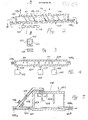
- Figs. 2, 3 and 4 show steps (I) and (II) of the method in diagrammatic form; during these steps the carburation reactor 101 and desulphurization reactor 102 are disposed such that only their respective upper zones 103 and 104 containing the gases are separated; the input stream of iron 105a, with a quantity of residual carbon of some 0.6% and at a temperature of 1500-1600°C, is introduced under the action of an electromagnetic pump or the like (not shown) into a channel 106 lined with consumable refractory material and passes through the reactors in the direction of the arrow F; a stream 107a of fossil coal, previously crushed to an average size of approximately 0.2 to 2 mm, is blown in by means of a series of nozzles 107, cooled and covered externally with refractory.
- the gases from the volatile materials present are released in the form of elements (N2, H2, S2) or CO and are removed via ducts 108 forming a current 108a.
- step (II) the desulphurization of the bath is carried out in several reactors containing the molten metal which flows in each of these counter to the current of the slag covering its surface; this slag is formed by the product of the desulphurization reaction and slag-forming agents 111a, for instance lime, added to the molten bath through the nozzles 111, and sulphur and other acid compounds from the ash.
- slag-forming agents 111a for instance lime
- the desulphurizing additives are advantageously differentiated in terms of the quality of the desulphurizing agents, the most effective being used in the final stages and the others, less costly than the former, in the initial stages, wherein the slag from the subsequent stages can also be re-used for this purpose after a hot desulphurization treatment.
- the movement of the slag on the surface of the bath runs counter to the flow of the bath; for this purpose, the ducts in which the iron bath flows are provided with an inclination in the direction of movement of the slag floating thereon so as to enable the slag to move under the effect of gravity; this inclination is overcome by the metal bath as a result of the use of electromagnetic linear motors 112 or the like.
- the countercurrent movement of the slag may be achieved by jets or sheets of gas acting on the floating slag in the direction opposite to the direction of flow of the molten metal.
- the desulphurization reactor 102 is divided into two or more separate zones 113a and 113b in which the desulphurizing agents are added in different quantities and compositions as discussed above depending on the need for desulphurization and therefore on the type of fossil coal or other fuel used.
- step (III) The desulphurization treatment is followed by step (III) using a reactor 115 shown diagrammatically in Fig. 5 in which the stream of desulphurized molten metal 105b emerging from step (II) is heat treated.
- the stream of molten metal 105b, entering the heating reactor 115 is divided into two portions 116 and 117, the smaller of which 116 forming, by way of non-limiting example, approximately 12 to 25% of the total, being subjected to complete oxidation while, as it has been brought to a higher level, it is being caused to fall into a free environment where it is struck by jets of oxygen which are advantageously symmetrical with respect to the vertical axis of the falling stream.
- Fig. 5 shows a diagram, in section along a vertical line, of the reactor 115 for the heating of the stream 105b of iron containing carbon; an electromagnetic pump 118 or like circulation means brings the portion 117 of the stream of iron designed to be oxidized through a rising duct 119 to a level where it is a few metres higher than the residual stream 117 which is also supplied to the reactor 115 through a respective duct 120 forming a hydraulic external seal for the gas (CO2) generated in the reactor which is removed through the duct 121; the reaction zone 122 is remote from the walls 123 of the reactor which are covered by refractory and thus protected from excessive heat stresses.
- CO2 gas
- the stream 116 at its inlet into the reactor 115, falls vertically and is struck by the jets of oxygen 124 and is thus decarburized; this decarburized stream then rejoins the main stream 117; the overall stream of molten metal 105c, reformed in this way, is removed from the reactor via the duct 125 to be supplied to step (IV).
- the fourth step of the method provides the electochemical conversion of the energy, generated by the reaction of the carbon oxidation by oxygen, into electrical power with contemporaneous generation of gas CO.
- the oxygen generating the reaction coming from the air supplied to the cathodic elements in ionic form, is carried through a thin wall of solid electrolyte.
- the electrical charges are carried through the iron bath to the anode.
- the potential energy, in the chosen conditions, is about 1.16 volt.
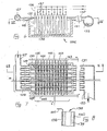
- the stream of molten metal, at the predetermined temperature of 1570-l750°C, is introduced, possibly divided into several portions, into one or more reactors formed by banks of fuel cells as shown in Figs. 6 and 7.
- Each reactor 126 comprises an inlet duct 127 for the molten iron bath following which the bath reaches the banks 129 through several connection ducts 128, each bank comprising a plurality of aligned elementary cells 130.
- the iron bath is then discharged from the reactor through the outlet ducts 131, comprising pressure reduction means 132, which converge together in the collector 133 from which the iron bath is brought back to the carburation step (I) with the stream 105 at a temperature which differs little from that at which it is introduced into the reactor while the CO gas is separated to form the gaseous outlet current 134 of the diagram of Fig 1.
- the cells 130 each have a cathode 135 which is advantageously but not necessarily of tubular form within which an input air current 136 is supplied.
- the tubular cathodes 135, as shown in Fig. 8 are formed, in a preferred embodiment, by cylindrical bodies with walls having an external layer 138 of thin solid electrolytic material, advantageously between 0.2 and 0.4 mm, supported by a layer 139 of porous material with a thickness of a few millimeters; the electrical supply is provided by an electrode 140 comprising a conductive component of metal type extending in a discontinuous manner so as not to block the current of gas, for example in the form of several sheets parallel to the axis of the tubular cathode placed between the solid electrolyte 138 and its porous support 139; a thin layer, with a thickness in the range of some tens of ⁇ m, of a conductive material of porous electronic type forming the actual cathode of the cell, is then placed in contact with the surface of this conductive element and the solid electrolyte.
- the conductor 141 for the current supply is then connected to the metal element of the electrode 140.
- a plane anode 142 of thin conductive material resistant to high temperatures is provided at the location of each tubular cathode 135 parallel to a generatrix of the outer cylindrical wall of the cathode; the structure of the anode is similar to that described for the electrode of the cathode, comprising a metal element is contact with a thin layer of porous conductive material which is, in turn, in contact with the bath; there may be a single anode for each cathode facing it or there may be an anode common to several cells of a bank.
- the anode 142 is in any case supported by a plane support wall 143 of non- conductive refractory material which separates the bank of cells from the adjacent bank.
- the tubular cathodes 135 of the first bank are connected electrically, via the respective conductors 141, to an external electrical collector 144 and the cathodes of the successive banks are each connected in series to the anode of the adjacent bank by the associated conductors 141; the anodes of the final bank (mth) or the anode common to the cells of the final bank are in turn connected by the conductors 145 to the external electrical collector 146.
- the voltage available between the collectors 144 and 146 is then m times greater than the voltage of the individual cell 130 and the current in the collectors 141 and 144 is n times greater than that generated in the individual cell.
- a high temperature co-generation plant i.e. a plant able simultaneously to produce two different forms of energy, specifically electrical energy and CO gas in quantities appropriate for large-scale industrial production.
- the method also has low production and plant costs as a result of the use of the same plant to produce both electrical energy and CO as well as the use of air and not oxygen as an oxidant and finally as a result of the high power yield connected with the direct conversion of the energy, wherein it is possible to achieve a specific consumption of carbon per kWh generated which is approximately half of that which can be achieved in thermoelectric plants. CO2 emissions are consequently also considerably reduced as well.
- industrial solutions relating to different sectors of energy production can also be provided enabling the achievement of a range of products which may be more complex than those of the co-generation plant, through two variants, the first of which relates to the method of operation of the plant and the second takes the form of a connection with known industrial plants disposed downstream of the high temperature co-generation plant.
- the first variant is based on the characteristic feature of the high temperature co-generation plant of the invention on the basis of which it is possible to produce in the heating step a temperature increase in the stream of molten metal which can be equal to or higher than that needed for the stationary operation of the plant as a whole.
- operation of the isothermic type takes place in the subsequent step of direct conversion of the energy; in the second case operation is not isothermic, i.e. there is a greater increase in the temperature of the bath in the heating step, followed by a cooling of the molten metal during the subsequent co-generation conversion.
- the two types of operation differ chiefly in respect of the quantity of gas produced while the electrical energy production remains the same, since the quantity of gas produced with isothermic operation is considerably higher than that produced with non-isothermic operation of the co-generation reactor.
- a current 134 of CO of 77,250 m3/h and electrical energy 147 of 100 MWh is produced by the co-generation step.
- a current 134 of CO of 46,800 m3/h and electrical energy 128 of 100 MWh is produced by the co-generation stage.
- the plant operates predominantly as a gasification plant supplied with air (rather than oxygen) thus enabling a reduction of costs as well as the other advantages mentioned above relating to the yield and the low sulphur content of the products.
- the electrical current 147 is supplied to the electrolysis plant 150 where a stream of water 151 is supplied producing as output a current 152 of O2 and a current 153 of H2.
- the hydrogen produced can then be used separately or supplied together with the CO gas to a further plant 154 from which many synthesis products 155 of major industrial interest can be obtained.
- the final products which can be obtained from this plant configuration comprising the electrolysis unit 150 and one or more other plants adapted to the conversion of the CO gas with H2 are evident: hydrogen, methanol, petrol, synthetic natural gas (SNG), ammonia.
- the plant described above may in fact be used for the production of hydrogen following which the hydrogen can be used for chemical syntheses (for the production of NH3 or the liquefaction of coal and so on); this plant is formed by the steps described above (carburation, desulphurization, heating and direct conversion) preferably operating in an isothermic manner during the conversion step and provided downstream with electrolysis units which use the energy in the form of direct current for the production of hydrogen.
- This gas can be further produced from the co-generation gas by the reaction known as the "water shift reaction”: CO + H2O ⁇ CO2 + H2 (4)
- electrolysis units for water use can advantageously be made of an electrolysis unit with solid electrolytes which operates at high temperature.
Landscapes
- Chemical & Material Sciences (AREA)
- Engineering & Computer Science (AREA)
- Electrochemistry (AREA)
- Chemical Kinetics & Catalysis (AREA)
- Sustainable Development (AREA)
- Sustainable Energy (AREA)
- Life Sciences & Earth Sciences (AREA)
- Manufacturing & Machinery (AREA)
- General Chemical & Material Sciences (AREA)
- Materials Engineering (AREA)
- Metallurgy (AREA)
- Organic Chemistry (AREA)
- Fuel Cell (AREA)
Applications Claiming Priority (2)
| Application Number | Priority Date | Filing Date | Title |
|---|---|---|---|
| IT8819762A IT1216078B (it) | 1988-03-14 | 1988-03-14 | Processo ed impianto per laproduzione di energia elettrica e gas per sintesi chimiche mediante ossidazione in bagni di metallo fuso. |
| IT1976288 | 1988-03-14 |
Publications (2)
| Publication Number | Publication Date |
|---|---|
| EP0333261A2 true EP0333261A2 (fr) | 1989-09-20 |
| EP0333261A3 EP0333261A3 (fr) | 1990-04-25 |
Family
ID=11161019
Family Applications (1)
| Application Number | Title | Priority Date | Filing Date |
|---|---|---|---|
| EP89200598A Withdrawn EP0333261A3 (fr) | 1988-03-14 | 1989-03-09 | Méthode et installation pour la production d'énergie électrique et de gaz pour des synthèses chimiques au moyen d'oxydation dans des bains métalliques fondus |
Country Status (2)
| Country | Link |
|---|---|
| EP (1) | EP0333261A3 (fr) |
| IT (1) | IT1216078B (fr) |
Cited By (9)
| Publication number | Priority date | Publication date | Assignee | Title |
|---|---|---|---|---|
| WO1999045607A1 (fr) * | 1998-03-03 | 1999-09-10 | Celltech Power, Llc | Groupe electrogene a carbone-oxygene |
| NL1008832C2 (nl) * | 1998-04-07 | 1999-10-08 | Univ Delft Tech | Werkwijze voor het omzetten van een koolstofomvattend materiaal, een werkwijze voor het bedrijven van een brandstofcel en een werkwijze voor het bedrijven van een brandstofcelstapel. |
| WO2003001617A3 (fr) * | 2001-06-25 | 2004-01-22 | Celltech Power Inc | Arrangement de couches d'electrodes dans un dispositif electrochimique |
| US7229710B2 (en) | 2001-11-20 | 2007-06-12 | Celltech Power, Inc. | Electrochemical system and methods for control thereof |
| WO2008138923A1 (fr) * | 2007-05-14 | 2008-11-20 | Imperial Innovations Limited | Pile à combustible pour une utilisation dans la génération d'électricité à partir d'un substrat carboné solide |
| US7678484B2 (en) | 2000-04-18 | 2010-03-16 | Celltech Power Llc | Electrochemical device and methods for energy conversion |
| US7745064B2 (en) | 2003-06-10 | 2010-06-29 | Celltech Power Llc | Oxidation facilitator |
| US7943270B2 (en) | 2003-06-10 | 2011-05-17 | Celltech Power Llc | Electrochemical device configurations |
| RU2430196C1 (ru) * | 2010-03-17 | 2011-09-27 | Бутаков Юрий Викторович | Способ снижения затрат электроэнергии на электролиз посредством гравитации |
Family Cites Families (4)
| Publication number | Priority date | Publication date | Assignee | Title |
|---|---|---|---|---|
| FR627049A (fr) * | 1926-01-03 | 1927-09-24 | Troate | Procédé de production directe d'énergie électrique par voie thermochimique et appareils permettant de le réaliser |
| US3138490A (en) * | 1961-02-28 | 1964-06-23 | Gen Electric | Fuel cell |
| DE3523487A1 (de) * | 1985-07-01 | 1987-01-08 | Kloeckner Humboldt Deutz Ag | Verfahren und anlage zur erzeugung von elektrischer energie |
| IT1197224B (it) * | 1986-09-15 | 1988-11-30 | Bruno Costa | Processo per la produzione di energia elettrica mediante ossidazione in metalli liquidi |
-
1988
- 1988-03-14 IT IT8819762A patent/IT1216078B/it active
-
1989
- 1989-03-09 EP EP89200598A patent/EP0333261A3/fr not_active Withdrawn
Cited By (13)
| Publication number | Priority date | Publication date | Assignee | Title |
|---|---|---|---|---|
| US6692861B2 (en) | 1998-03-03 | 2004-02-17 | Celltech Power, Inc. | Carbon-oxygen fuel cell |
| WO1999045607A1 (fr) * | 1998-03-03 | 1999-09-10 | Celltech Power, Llc | Groupe electrogene a carbone-oxygene |
| NL1008832C2 (nl) * | 1998-04-07 | 1999-10-08 | Univ Delft Tech | Werkwijze voor het omzetten van een koolstofomvattend materiaal, een werkwijze voor het bedrijven van een brandstofcel en een werkwijze voor het bedrijven van een brandstofcelstapel. |
| WO1999052166A3 (fr) * | 1998-04-07 | 2000-01-20 | Univ Delft Tech | Procede servant a convertir un materiau contenant du carbone, procede de mise en service d'un empilement de piles a combustible et pile a combustible |
| US6607853B1 (en) | 1998-04-07 | 2003-08-19 | Technische Universitiet Delft | Method of converting a carbon-comprising material, method of operating a fuel cell stack, and a fuel cell |
| US7678484B2 (en) | 2000-04-18 | 2010-03-16 | Celltech Power Llc | Electrochemical device and methods for energy conversion |
| US7943271B2 (en) | 2000-04-18 | 2011-05-17 | Celltech Power Llc | Electrochemical device and methods for energy conversion |
| WO2003001617A3 (fr) * | 2001-06-25 | 2004-01-22 | Celltech Power Inc | Arrangement de couches d'electrodes dans un dispositif electrochimique |
| US7229710B2 (en) | 2001-11-20 | 2007-06-12 | Celltech Power, Inc. | Electrochemical system and methods for control thereof |
| US7745064B2 (en) | 2003-06-10 | 2010-06-29 | Celltech Power Llc | Oxidation facilitator |
| US7943270B2 (en) | 2003-06-10 | 2011-05-17 | Celltech Power Llc | Electrochemical device configurations |
| WO2008138923A1 (fr) * | 2007-05-14 | 2008-11-20 | Imperial Innovations Limited | Pile à combustible pour une utilisation dans la génération d'électricité à partir d'un substrat carboné solide |
| RU2430196C1 (ru) * | 2010-03-17 | 2011-09-27 | Бутаков Юрий Викторович | Способ снижения затрат электроэнергии на электролиз посредством гравитации |
Also Published As
| Publication number | Publication date |
|---|---|
| IT1216078B (it) | 1990-02-22 |
| EP0333261A3 (fr) | 1990-04-25 |
| IT8819762A0 (it) | 1988-03-14 |
Similar Documents
| Publication | Publication Date | Title |
|---|---|---|
| US3616334A (en) | Electrically and chemically coupled power generator and hydrogen generator | |
| US9486771B2 (en) | Electrochemical carbon monoxide production | |
| EP0180941B1 (fr) | Système de piles à combustible | |
| US5312843A (en) | Method for producing methanol by use of nuclear heat and power generating plant | |
| US4412895A (en) | System using SO2 as an anode depolarizer in a solid oxide electrolyte electrolysis cell for H2 production from steam | |
| US20110206566A1 (en) | Syngas production systems | |
| US20110171545A1 (en) | Carbon fuel particles used in direct carbon conversion fuel cells | |
| JP2018519414A (ja) | 二酸化炭素および硫化水素を共処理する方法 | |
| JP2000501227A (ja) | 高温燃料電池設備の運転方法及び高温燃料電池設備 | |
| US4826740A (en) | Process for generating electrical energy by oxidation of a solid fuel in liquid metal | |
| US20050064259A1 (en) | Hydrogen diffusion electrode for protonic ceramic fuel cell | |
| Gopalan et al. | Regenerative, coal-based solid oxide fuel cell-electrolyzers | |
| US3085053A (en) | Reversed fuel cell and oxygen generator | |
| US20220081295A1 (en) | System and method for adjusting pressure in a reservoir and system for producing at least one energy carrier | |
| EP3906356B1 (fr) | Système et procédé de réglage de la pression dans un réservoir souterrain | |
| US3192070A (en) | Fuel cell | |
| US4143515A (en) | Converting fossil fuel and liberated water constituents to electrical energy, synthetic natural gas or miscellaneous hydrocarbons while avoiding befoulment of environment | |
| US4092129A (en) | Process for producing methane rich gas | |
| CN1087951A (zh) | 用矿石直接炼钢的方法及设备 | |
| Mogensen et al. | Fuel cells-familiar principles for electricity generation | |
| Audasso et al. | Molten carbonate fuel cells in integrated systems for the exploitation of poor fuels and the segregation of CO2 | |
| WO1999052166A2 (fr) | Procede servant a convertir un materiau contenant du carbone, procede de mise en service d'un empilement de piles a combustible et pile a combustible | |
| Jacob | A new type of SOFC for conversion of high temperature heat to electricity without Carnot limitation | |
| US885054A (en) | Gas element for converting the energy of combustible or other suitable reducing substances to electric current. | |
| EP4674988A1 (fr) | Procédé de production d'acier vert |
Legal Events
| Date | Code | Title | Description |
|---|---|---|---|
| PUAI | Public reference made under article 153(3) epc to a published international application that has entered the european phase |
Free format text: ORIGINAL CODE: 0009012 |
|
| AK | Designated contracting states |
Kind code of ref document: A2 Designated state(s): DE FR GB GR IT NL SE |
|
| PUAL | Search report despatched |
Free format text: ORIGINAL CODE: 0009013 |
|
| AK | Designated contracting states |
Kind code of ref document: A3 Designated state(s): DE FR GB GR IT NL SE |
|
| 17P | Request for examination filed |
Effective date: 19901220 |
|
| 17Q | First examination report despatched |
Effective date: 19920423 |
|
| STAA | Information on the status of an ep patent application or granted ep patent |
Free format text: STATUS: THE APPLICATION IS DEEMED TO BE WITHDRAWN |
|
| 18D | Application deemed to be withdrawn |
Effective date: 19941001 |