EP0333324A2 - Codes en treillis à adaptation de spectre zéro pour des canaux à réponse partielle - Google Patents
Codes en treillis à adaptation de spectre zéro pour des canaux à réponse partielle Download PDFInfo
- Publication number
- EP0333324A2 EP0333324A2 EP89301416A EP89301416A EP0333324A2 EP 0333324 A2 EP0333324 A2 EP 0333324A2 EP 89301416 A EP89301416 A EP 89301416A EP 89301416 A EP89301416 A EP 89301416A EP 0333324 A2 EP0333324 A2 EP 0333324A2
- Authority
- EP
- European Patent Office
- Prior art keywords
- channel
- zero
- code
- output
- frequency
- Prior art date
- Legal status (The legal status is an assumption and is not a legal conclusion. Google has not performed a legal analysis and makes no representation as to the accuracy of the status listed.)
- Withdrawn
Links
Images


Classifications
-
- H—ELECTRICITY
- H04—ELECTRIC COMMUNICATION TECHNIQUE
- H04L—TRANSMISSION OF DIGITAL INFORMATION, e.g. TELEGRAPHIC COMMUNICATION
- H04L25/00—Baseband systems
- H04L25/38—Synchronous or start-stop systems, e.g. for Baudot code
- H04L25/40—Transmitting circuits; Receiving circuits
- H04L25/49—Transmitting circuits; Receiving circuits using code conversion at the transmitter; using predistortion; using insertion of idle bits for obtaining a desired frequency spectrum; using three or more amplitude levels ; Baseband coding techniques specific to data transmission systems
- H04L25/497—Transmitting circuits; Receiving circuits using code conversion at the transmitter; using predistortion; using insertion of idle bits for obtaining a desired frequency spectrum; using three or more amplitude levels ; Baseband coding techniques specific to data transmission systems by correlative coding, e.g. partial response coding or echo modulation coding transmitters and receivers for partial response systems
Definitions
- the present invention relates to matched spectral null trellis codes for partial response channels with a view to improving techniques for transmission of binary digital data over partial response channels using maximum likelihood sequence detection (PRML), and provices a method of coding an input string for a partial response channel to provide an output having a preselectable coding rate with an improved coding gain, the method comprising the steps of:
- Reference [E] demonstrates the use of a simplified Viterbi detector in conjunction with the rate 1/2, Miller-squared code on a full response tape channel.
- the code has a spectral null at zero frequency, implying bounded accumulated charge, and the receiver operates with a degenerate state diagram which tracks only the accumulated charge. Coding gain arises from the fact that the code has minimum free Hamming distance 2, versus the minimum distance of 1 for uncoded binary data.
- Reference [F] describes binary codes wherein both the code power spectral density and its low order derivatives vanish at zero frequency, and the minimum Hamming distance of a K-th order zero-disparity code is at least 2(K + 1).
- the present invention present an approach to the stated desiderata and reference is made to embodiments thereof disclosed hereinafter for coding input strings at high rate to improve the coding gain of partial response channels and provide an output of improved reliability.
- the method used involves determining each frequency at which there is a zero in the transfer function of a partial response channel, and encoding an input string into a binary code string having a power spectrum value of zero for each such frequency. (Those frequencies at which the power spectrum value is zero are herein defined as "spectral null frequencies"; i.e., those frequencies at which no energy is transmitted.)
- a channel output sequence is generated responsively to transmission of the code string through the channel. The most probable code sequence is calculated from the channel output sequence, and decoded to provide the output.
- the code strings have the property that the code power spectrum vanishes at those frequencies where the channel transfer function vanishes. This "matching" of spectral null frequencies produces enhanced coding gains by-' exploiting the memory inherent in the channel. Additional coding gain is achieved by increasing the order of the spectral null of the code strings at these frequencies.
- the present invention provides a method for coding an input string for a partial response channel to provide an output having a preselectable coding rate and a reliability determined by a preselectable coding gain, comprising the steps of:
- matched spectral nulls i.e., the trellis code spectrum is, designed to have nulls at frequencies where the channel transfer function has a null, thereby providing improved coding gains and reduced Viterbi decoder complexity.
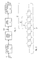
- input data such as in the form of binary symbol strings, is transmitted from a bus 10 to an encoder 11.
- Encoder 11 produces a binary code symbol sequence which serves as input to a partial response channel 12.
- This code has a power spectrum of zero for each frequency at which there is a zero in the transfer function of the channel 12; i.e., the code sequences have spectral nulls which match those of the partial response channel.
- a channel output sequence is generated by partial response channel 12 and detected at the channel output by a detector 13. This detector calculates the most probable code sequence from the channel output sequence.
- Detector 13 reduces computational and hardware requirements by tracking only the frequency spectral content of the channel output sequence, thereby producing a near maximum-likelihood estimate (or most probable code sequence) of the transmitted original data sequence supplied via bus 10.
- a decoder 14 then generates from the detected sequence the matched spectral null code output data in a bus 15.
- This code format and code detection technique are founded on an analysis of Euclidean distance properties of partial response output sequences generated by inputs satisfying the matched spectral null constraints, which will now be briefly described.
- the Appendix shows the derivation of the novel bounds on the free Euclidean distance of the channel output sequences, which translate into the coding gains provided by matched spectral null codes in the presence of additive white Gaussian noise. These bounds validate the coding technique depicted in Fig. 1. Specifically, these coding gain bounds are as follows:
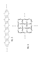
- Fig. 2 depicts a canonical state diagram for binary sequences with a spectral null at zero frequency wherein the sequences are generated in one coordinate (i.e., x) direction;
- Fig. 3 depicts a canonical state diagram for binary sequences with a spectral null at 1/2T, where T is the code symbol period; and
- Fig. 4 depicts a canonical state diagram for binary sequences with spectral nulls at zero frequency and at 1/2T.
- Fig. 4 is a canonical state diagram wherein the sequences are generated in two coordinate (i.e., x and y) directions, employing the k-way interleaving technique disclosed in US-A-4 567 464.
- the capacity of a constrained system of sequences is the maximum achievable rate of a code satisfying the specified constraints.
- the published sliding block code construction methods of Adler-Coppersmith-Hassner and Karabed-Marcus form no part of the present invention, but can be used to construct codes at rates arbitrarily close to the capacity.
- the capacity C N of the diagrams , and is given by: so it will be understood that for any desired rate k/n ⁇ 1, a value of N can be selected large enough to permit the construction of a rate k/n spectral null code with that rate.
- the coding gain is given by Bounds 1, 2 and 3 above.
- the codes incorporate limitations on the maximum run-length of zero output samples so that only those code strings having less than a predetermined number of consecutive zeroes in their output channel sequences are produced in order to improve timing and gain control decisions during detection. Also, only the code strings having a predetermined level of reliability are produced; and a finite-state encoder and sliding block decoder are constructed for a code satisfying these maximum run-length constraints on zero samples, as well as eliminating "quasi-catastrophic" sequences which might degrade the worst case coding gain. (Quasi-catastrophic sequences are those represented by more than one distinct path through the state diagram describing the constraint).
- the trellis is derived from the p-th power of the state diagram.
- the p-th power of a state diagram G is the state diagram H with the same states as G, and an edge from state s ; to Sj for each path of length p in G from s, to s j .
- the edge label in H is the sequence of p symbols generated by the corresponding length p path in G).
- the power p is chosen to be the period of the diagram, which is the greatest common divisor of cycle lengths in the diagram. For the diagrams and , the period is 2. For the diagrams , the period is 4.
- Bound 4 (Higher order nulls): For a channel with K-th order null at zero frequency or one-half the Nyquist frequency, the minimal trellis describing the output sequences produced by the constraint diagram for sequences with a matched spectral null of order L satisfies the condition:
- the new codes significantly reduce the Viterbi decoder complexity required to achieve coding gains on the order of 3dB, compared to the codes obtained by previous methods proposed by Reference [A] and Reference [C].
- the unique method provides a way to construct families of high rate codes for channels which were not addressed by earlier methods; namely, those with transfer polynomials other than (1 ⁇ D N ).
- the biphase code for the dicode channel previously published in Reference [C] is generated imme- diateiy by the matched spectral nulls technique, representing a special case.
- the biphase code is described exactly by the subdiagram .
- This subdiagram has capacity precisely .5, and, in this case, the biphase code provides a 100% efficient (rate 1/2) code with particularly simple block code structure.
- the coding gain of the code over the uncoded channel, namely 4.8dB, is given by Bound 1.
- Bound 2 gives a new application for the biphase code on the (1 - D) 2 channel, providing a 7dB coding gain over the uncoded channel.
- the trellis diagram derived from the second power of provides the structure for a full maximum-likelihood decoder since the code is 100% efficient.
- Table 1 shows a 3-state constrained system derived from the 6th power of .
- the box in row i and column j in the table contains a letter which identifies a list of allowable 6-bit codewords which can originate in state i and terminate in state j.
- the number in parentheses indicates the number of codewords in the list.
- the 6-bit codewords in the list are given below the table.
- a rate 4/6 finite state encoder is derived by selecting 16 codewords originating from each state and then assigning the 16 distinct 4-bit data words to corresponding codewords.
- a preferred embodiment is given in Table 2. It is derived from Table 1 by eliminating from row 1 the codewords in list A, and then assigning in a specific manner the 16 distinct 4-bit data words to the 16 codewords originating from each state. The assignment specified here was chosen to simplify the Boolean function which gives the data to codeword correspondence.
- Entries in the table are in the form C 1 C 2 C 3 C 4 C 5 C 6 /t 1 t 2 where C 1 C 2 C 3 C 4 C 5 C 6 is the codeword generated, and tlt2 is the next encoder state.
- the corresponding sliding block decoder is given in Table 3. Entries in the table are in the form C 1 C 2 C 3 C 4 C 5 C 6 /L where C 1 C 2 C 3 C 4 C 5 C 6 is the received codeword, and L represents the look-ahead decision bit. This bit is a function of the codeword C 7 C 8 C 9 C 10 C 11 C 12 , given by: The symbol "-" denotes a "don't care" value. In the data column, b 1 b 2 b 3 b 4 represents the decoded data.
- the encoder and decoder can be reduced to hardware by conventional techniques, using a ROM-based approach or a Boolean logic implementation.
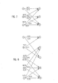
- Fig. 5 shows the reduced complexity detector trellis for the rate 4/6 code on the dicode channel, derived from the second power of by incorporating the effect of the channel.
- This 3-state trellis provides the structure for the Viterbi detection algorithm, which is derived by conventional techniques.
- the code provides a coding gain of 3dB (see Bound 1).
- the code can be applied in an interleaved manner on interleaved dicode channels, providing the same coding gain of 3dB.
- Fig. 6 depicts the trellis structure for the Viterbi detector when used on the (1 - D) 2 channel.
- the code provides a coding gain of 4dB (see Bound 2).
- Figs. 7 and 8 depict the Viterbi detector trellis structures for the class 1 and class 2 applications, respectively, of the modified code.
- the matched spectral null subdiagram is the minimum state diagram which generates the required spectral null at one-half the Nyquist frequency.
- This modified code is decoded by adding (modulo 2) the same vector v to the detected codestream, and then passing the result to original decoder of Table 2.
- the modified code provides coding gains of 3dB for class 1 and 4dB for class 2, respectively.
- the modified code can be applied in an interleaved manner on interleaved class 1 channels, providing the same coding gain of 3dB.
- Fig. 9 is a tabular representation of a 15-state Viterbi detector trellis. This is required when the code is applied in an interleaved fashion to the extended class 4 channel, with transfer polynomial (1 - D) (1 + D) 2 . It is based upon the forth power of the diagram G4 1/2T . The code provides a 3dB coding gain (see Bound 3).
- Table 4 shows a two state constrained system derived from the 8th power of Gg .
- the box in row i and column j in the table contains a letter which identifies a list of allowable 8-bit codewords which can originate in state i and terminate in state j.
- the number in parentheses indicates the number of codewords in the list.
- the 8-bit codewords in each list are given below the table in hexadecimal form, each codeword being described by a pair of hex symbols.
- any 2 6 64 codewords are selected from each row.
- the corresponding decoder Independently of the data word to codeword assignment selected, the corresponding decoder will be a block decoder, decoding each 8-bit codeword directly into a unique 6- bit data word.
- Table 5 gives a specific assignment of the 64 distinct 6-bit data words, each represented by a pair of octal symbols, to a specific subset of 64 codewords from row 1 of the table, corresponding to the codewords originating from state 1.
- the codeword represented by the hex symbols CC has been omitted.
- the notation "UV x WYZ” refers to the words “UV UW UY VW VY VZ” in the specific order indicated.
- Data to codeword assignment for encoder state 1 of rate 6/8 code with spectral null at f 0
- the block decoder is also derived from the assignments of Table 5 by reading from right to left.
- the encoder and decoder can be reduced to hardware by conventional techniques, using a ROM-based approach or a Boolean logic implementation.
- Fig. 10 shows the reduced complexity detector trellis for the rate 6/8 code on the dicode channel, derived from the second power of by incorporating the effect of the channel.
- This 5-state trellis provides the structure for the Viterbi detection algorithm.
- the code provides a coding gain of 3dB (see Bound 1).
- the code can be applied in an interleaved manner on interleaved dicode channels, providing the same coding gain of 3dB.
- the Viterbi trellis structure When used on the (1 - D) 2 channel, the Viterbi trellis structure is derived from the second power of , in an analogous fashion to the trellis derivations above.
- the code provides a coding gain of 3dB (see Bound 2).
- the matched spectral null subdiagram is the minimum state diagram which generates the required spectral null at one-half the Nyquist frequency.
- This modified code is decoded by adding (modulo 2) the same vector ⁇ to the detected codestream, and then passing the result to original decoder of Table 4.
- the coding gain for the modified 6/8 code on both the class 1 and class 2 channels is 3dB.
- the modified code can be applied in an interleaved manner on interleaved dicode channels, providing the same coding gain of 3dB.
- the code When applied in an interleaved fashion to the extended class 4 channel, the code provides a coding gain of 1.8dB (see Bound 3). It will now be understood by those skilled in the art that the Viterbi detector trellises for the extended class 4 application can be derived in the same manner as described in the last paragraph of the section describing the Rate 2/3 codes.
- Table 6 shows a four state constrained system derived from the 10th power of .
- the box in row i and column j in the table contains a letter which identifies a list of allowable 10-bit codewords which can originate in state i and terminate in state j.
- the number in parentheses indicates the number of codewords in the list.
- the notation A is used to denote the list which is obtained by bit-wise complementing (that is, adding 1111111111 modulo 2) each codeword in list A.
- any 2 8 2 56 codewords are selected from each row.
- Table 7 gives a structured assignment of the 256 distinct 8-bit data words, to the specific subsets of 256 codewords selected from the rows of the table.
- the set DD can be any subset of 132 words from the 162 words in list D.
- the decoder is also derived from the assignments of Table 7.
- the decoding rules, involving look-ahead of one codeword, are given in Table 8.
- the decoder is a sliding block decoder, producing 8 data bits for each sliding block consisting of two 10 bit codewords, implying a maximum error length of two data bytes.
- the current codeword is denoted y n-1 and the next codeword is denoted y n .
- the decoder rules determine which entry of the encoder table to use to decode the codeword.
- the encoder 11 and decoder 14 can be reduced to hardware by conventional techniques, using a ROM-based approach or a Boolean logic implementation.
- the finite-state encoder shown in Table 7 may be of the type shown in Fig. 11 comprising an input shift register 51, a state shift register 52, and a read only memory (ROM) 53.
- Shift registers are two-terminal input/output machines with feedforward path.
- Input shift register 51 takes 8 input bits x 1 x 2,..., x 8 as input at every clock cycle C, and outputs y 1 ,y 2 ,...,y 1 during the cycle C.
- State register 52 takes 2 bits of state information S1 and s 2 as inputs every clock cycle C, and outputs si and s 2 during the clock cycle C.
- ROM 53 takes 10-bit (8 input bits + 2 state bits) address inputs every cycle C, and provides 12-bit (2 updated state bits + 10 output bits) outputs every cycle C. The updated state bits are sent via 54 to the state register for the next cycle C.
- the sliding block decoder 14 (which, as noted, follows the rules shown in Table 8) may be of the type shown in Fig. 12.
- This decoder 14 comprises an input shift register 61, a ROM 62, a delay shift register 63, a counter 64, a decision logic g 65 and an 'exclusive-or' logic gate 66.
- ROM 62 takes a 10-bit input address and has an 8-bit data output.
- delay register 63 stores the output of the ROM for use at the next clock cycle.
- input shift register 61 takes 10 input bits y 1 ,y 2 ,...,y 10 .
- the output of input shift register 61 is y 1 ,y 2 ,...,y 1 for the duration of the cycle.
- This output is connected to counter 64, whose two 4-bit outputs v and v', computed in the same clock cycle, represent the number of ones in y 1 ,...,y 10 and in y 1 ,...,y 8 , respectively.
- the output u of the decision logic g is one or zero based on the inputs v and v to g.
- the function g is specified to produce output variable u according to the rule:
- the variable u is one of the inputs to exclusive-or gate 66, whose other input is the 8 bit contents of delay shift register 63 stored from the previous clock cycle.
- Fig. 13 shows the reduced complexity detector trellis for the rate 8/10 code on the dicode channel, derived from the second power of by incorporating the effect of the channel.
- This 6-state trellis provides the structure for the Viterbi detection algorithm.
- the code provides a coding gain of 3dB (see Bound 1).
- the code can be applied in an interleaved manner on interleaved dicode channels, providing the same coding gain of 3dB.
- the Viterbi trellis structure When used on the (1 - D) 2 channel, the Viterbi trellis structure is derived from the second power of , in an analogous fashion to the trellis derivations above.
- the code provides a coding gain of 1.8dB (see Bound 2).
- the matched spectral null subdiagram is the minimum state diagram which generates the required spectral null at one-half the Nyquist frequency.
- the state diagram is used to simplify the resulting code.
- This modified code is decoded by adding (modulo 2) the same vector ⁇ to the detected codestream, and then passing the result to the decoder 14, more fully shown in Fig. 12.
- the coding gain for the modified 8 / 10 code on the class 1 and class 2 channels are 3dB and 1.8dB, respectively.
- the modified code can be applied in an interleaved manner on interleaved dicode channels, providing the same coding gain of 3dB.
- the code When applied in an interleaved fashion to the extended class 4 channel, the code provides a coding gain of 1.8dB (see Bound 3). Again, the Viterbi detector trellises for the extended class 4 application are derived in the manner described in connection with Rate 2/3 codes.
- Reference [A] describes codes for the (1 - D) channel which achieve 3dB coding gain at rates 2/3, 3/4 and 4,5.
- Table 9 the parameters of these prior art codes to achieve a 3dB coding gain are compared to those of the comparable codes presented in this application to provide an identical coding gain.
- ZRL Limit-Runlength-Limit
- Theorem constitutes the basis for the bounds on the coding gains of matched spectral null trellis codes: where e n are integer-values coefficients, and assume e o is nonzero. If e(D) is divisible by (1 - D) K , then That is, the Euclidean weight of the sequence of coefficients of e(D), denoted
- Lemma 1 Lemma 1
- Lemma 2 Lemma 1
- the Euclidean weight of the output sequence satisfies:
- the Euclidean weight of the output sequence can be written as It will be seen that if g(D) has no changes of sign in the sequence of coefficients, then since the contribution to Equation (A3) of the term corresponding to the first nonzero coefficient to Equation (A3) is at least 1, as is the contribution corresponding to the zero coefficient following the last nonzero coefficient.
- Equation (A6) g(D) has L changes in sign, L ⁇ 1, which occur at coefficients g n1 gn2 ,...,gn L .
- Equation (A5) and (A7) arise from the contributions corresponding to the first nonzero coefficient and the first zero coefficient after the last nonzero coefficient.
- Equation (A6) two cases must be considered:
- Theorem can now be applied to verify the bounds on coding gain of matched spectral null trellis codes.
Landscapes
- Physics & Mathematics (AREA)
- Spectroscopy & Molecular Physics (AREA)
- Engineering & Computer Science (AREA)
- Computer Networks & Wireless Communication (AREA)
- Signal Processing (AREA)
- Error Detection And Correction (AREA)
- Signal Processing For Digital Recording And Reproducing (AREA)
- Dc Digital Transmission (AREA)
Applications Claiming Priority (2)
| Application Number | Priority Date | Filing Date | Title |
|---|---|---|---|
| US07/169,920 US4888779A (en) | 1988-03-18 | 1988-03-18 | Matched spectral null trellis codes for partial response channels |
| US169920 | 1988-03-18 |
Publications (2)
| Publication Number | Publication Date |
|---|---|
| EP0333324A2 true EP0333324A2 (fr) | 1989-09-20 |
| EP0333324A3 EP0333324A3 (fr) | 1992-07-22 |
Family
ID=22617763
Family Applications (1)
| Application Number | Title | Priority Date | Filing Date |
|---|---|---|---|
| EP19890301416 Withdrawn EP0333324A3 (fr) | 1988-03-18 | 1989-02-15 | Codes en treillis à adaptation de spectre zéro pour des canaux à réponse partielle |
Country Status (3)
| Country | Link |
|---|---|
| US (1) | US4888779A (fr) |
| EP (1) | EP0333324A3 (fr) |
| JP (1) | JPH0821957B2 (fr) |
Cited By (6)
| Publication number | Priority date | Publication date | Assignee | Title |
|---|---|---|---|---|
| EP0458490A3 (en) * | 1990-05-22 | 1993-10-06 | International Business Machines Corporation | Look-ahead for coded signal processing channels |
| EP0633679A1 (fr) * | 1993-06-14 | 1995-01-11 | AT&T Corp. | Schéma de codage pour canaux à l'interférence intersymbole |
| WO1997006624A1 (fr) * | 1995-08-03 | 1997-02-20 | Seagate Technology, Inc. | Codeur/decodeur a point de puissance spectrale nulle appariee |
| EP0713296A3 (fr) * | 1994-11-18 | 1998-01-07 | Seagate Technology International | Codes spectraux zéro correspondant les uns aux autres pour canaux de réponse incomplets |
| EP0720302A3 (fr) * | 1994-12-28 | 1999-03-17 | Sony Corporation | Méthode de modulation de code, méthode de démodulation de code et méthode de détéction de code |
| US7127665B2 (en) * | 2001-10-03 | 2006-10-24 | Sony Corporation | Trellis code detector and decoder |
Families Citing this family (47)
| Publication number | Priority date | Publication date | Assignee | Title |
|---|---|---|---|---|
| US5150381A (en) * | 1989-02-16 | 1992-09-22 | Codex Corporation | Trellis shaping for modulation systems |
| NZ235034A (en) * | 1989-09-19 | 1992-11-25 | Ericsson Telefon Ab L M | Determining quality factors for binary digits in viterbi-analysis of a signal |
| US5077743A (en) * | 1989-09-20 | 1991-12-31 | Board Of Trustees Of The University Of Illinois | System and method for decoding of convolutionally encoded data |
| US5208834A (en) * | 1991-03-15 | 1993-05-04 | International Business Machines Corporation | Lexicographical encoding and decoding of state-dependent codes |
| US5220466A (en) * | 1991-05-21 | 1993-06-15 | International Business Machines Corporation | Method and apparatus for digital filter control in a partial-response maximum-likelihood disk drive system |
| US5327440A (en) * | 1991-10-15 | 1994-07-05 | International Business Machines Corporation | Viterbi trellis coding methods and apparatus for a direct access storage device |
| US5196849A (en) * | 1992-01-31 | 1993-03-23 | International Business Machines Corporation | Method and apparatus for implementing PRML codes with maximum ones |
| US5257272A (en) * | 1992-04-15 | 1993-10-26 | International Business Machines Corporation | Time-varying modulo N trellis codes for input restricted partial response channels |
| US5280489A (en) * | 1992-04-15 | 1994-01-18 | International Business Machines Corporation | Time-varying Viterbi detector for control of error event length |
| US5424881A (en) | 1993-02-01 | 1995-06-13 | Cirrus Logic, Inc. | Synchronous read channel |
| WO1994029989A1 (fr) * | 1993-06-14 | 1994-12-22 | International Business Machines Corporation | Systeme d'egalisation adaptive a reponse partielle et a prevision de bruit, pour des voies a points de puissance spectrale nulle |
| GB9324918D0 (en) * | 1993-12-04 | 1994-01-26 | Hewlett Packard Ltd | High-density data recording |
| US5497384A (en) * | 1993-12-29 | 1996-03-05 | International Business Machines Corporation | Permuted trellis codes for input restricted partial response channels |
| US5619539A (en) * | 1994-02-28 | 1997-04-08 | International Business Machines Corporation | Data detection methods and apparatus for a direct access storage device |
| US5485472A (en) * | 1994-05-16 | 1996-01-16 | International Business Machines Corporation | Trellis codes with algebraic constraints for input restricted partial response channels |
| WO1995035538A1 (fr) * | 1994-06-21 | 1995-12-28 | Seo Michael J | Procede de decodage et decodage de signaux a l'aide d'un code de correction rapide d'erreur algebrique |
| US5537424A (en) * | 1994-08-12 | 1996-07-16 | International Business Machines Corporation | Matched spectral null codes with partitioned systolic trellis structures |
| US5548600A (en) * | 1994-08-12 | 1996-08-20 | International Business Machines Corporation | Method and means for generating and detecting spectrally constrained coded partial response waveforms using a time varying trellis modified by selective output state splitting |
| US5916315A (en) * | 1994-08-23 | 1999-06-29 | Ampex Systems Corporation | Viterbi detector for class II partial response equalized miller-squared signals |
| CA2147087A1 (fr) * | 1995-04-13 | 1996-10-14 | Guy Begin | Methode et appareil de correction de suites de branchement representant des bits utiles codes et de transformation de ces bits en bits utiles approximatifs |
| US5638065A (en) * | 1995-06-13 | 1997-06-10 | International Business Machines Corporation | Maximum-likelihood symbol detection for RLL-coded data |
| US5809080A (en) * | 1995-10-10 | 1998-09-15 | Mitel Semiconductor Americas Inc. | System and method for coding partial response channels with noise predictive Viterbi detectors |
| US5790571A (en) * | 1995-12-11 | 1998-08-04 | Seagate Technology, Inc. | Coding data in a disc drive according to a code having desired algebraic characteristics |
| US5809081A (en) * | 1996-05-20 | 1998-09-15 | Mitel Semiconductor Americas Inc. | System and method for encoding data such that after precoding the data has a pre-selected parity structure |
| JP3207123B2 (ja) * | 1996-08-07 | 2001-09-10 | 富士通株式会社 | 最尤検出方法及び情報記録再生装置 |
| US5910969A (en) * | 1996-11-05 | 1999-06-08 | Lucent Technologies Inc. | Method of detecting DC-free sequences |
| US6188436B1 (en) | 1997-01-31 | 2001-02-13 | Hughes Electronics Corporation | Video broadcast system with video data shifting |
| US6091455A (en) * | 1997-01-31 | 2000-07-18 | Hughes Electronics Corporation | Statistical multiplexer for recording video |
| US6005620A (en) * | 1997-01-31 | 1999-12-21 | Hughes Electronics Corporation | Statistical multiplexer for live and pre-compressed video |
| US6084910A (en) * | 1997-01-31 | 2000-07-04 | Hughes Electronics Corporation | Statistical multiplexer for video signals |
| US6163421A (en) * | 1997-09-05 | 2000-12-19 | Sony Corporation | Azimuth magnetic recording and reproducing apparatus and method employing waveform equalization |
| US6275458B1 (en) | 1999-02-18 | 2001-08-14 | Terrence L. Wong | Method and apparatus for reading and writing a multi-level signal from an optical disc |
| US6408419B1 (en) | 1999-07-01 | 2002-06-18 | Infineon Technologies North America Corp. | Trellis code for extended partial response maximum likelihood (EPRML) channel |
| US6385255B1 (en) | 1999-08-06 | 2002-05-07 | Calimetrics, Inc. | Coding system and method for partial response channels |
| US6415415B1 (en) | 1999-09-03 | 2002-07-02 | Infineon Technologies North America Corp. | Survival selection rule |
| US6680980B1 (en) | 1999-09-03 | 2004-01-20 | Infineon Technologies North America Corp. | Supporting ME2PRML and M2EPRML with the same trellis structure |
| US7096412B2 (en) | 2000-06-19 | 2006-08-22 | Trellisware Technologies, Inc. | Method for iterative and non-iterative data detection using reduced-state soft-input/soft-output algorithms for complexity reduction |
| US6456208B1 (en) * | 2000-06-30 | 2002-09-24 | Marvell International, Ltd. | Technique to construct 32/33 and other RLL codes |
| US6504493B1 (en) | 2000-10-31 | 2003-01-07 | Marvell International, Ltd. | Method and apparatus for encoding/decoding data |
| US7286065B1 (en) | 2001-03-05 | 2007-10-23 | Marvell International Ltd. | Method and apparatus for DC-level constrained coding |
| US6661356B1 (en) | 2001-03-05 | 2003-12-09 | Marvell International, Ltd. | Method and apparatus for DC-level constrained coding |
| US7184237B2 (en) * | 2001-08-21 | 2007-02-27 | Seagate Technology Llc | Method and apparatus for selecting equalization targets |
| US7084789B2 (en) * | 2003-11-17 | 2006-08-01 | Seagate Technology Llc | DC-free code having limited error propagation and limited complexity |
| US7191386B2 (en) * | 2004-06-29 | 2007-03-13 | Seagate Technology Llc | Method and apparatus for additive trellis encoding |
| US7002492B2 (en) * | 2004-07-07 | 2006-02-21 | Seagate Technology Llc | High rate running digital sum-restricted code |
| US8139628B1 (en) | 2005-01-10 | 2012-03-20 | Marvell International Ltd. | Method and device to compensate for baseline wander |
| US8060808B2 (en) * | 2005-02-28 | 2011-11-15 | The Regents Of The University Of California | Method for low distortion embedding of edit distance to Hamming distance |
Family Cites Families (8)
| Publication number | Priority date | Publication date | Assignee | Title |
|---|---|---|---|---|
| US4413251A (en) * | 1981-07-16 | 1983-11-01 | International Business Machines Corporation | Method and apparatus for generating a noiseless sliding block code for a (1,7) channel with rate 2/3 |
| US4463344A (en) * | 1981-12-31 | 1984-07-31 | International Business Machines Corporation | Method and apparatus for generating a noiseless sliding block code for a (2,7) channel with rate 1/2 |
| NL8204856A (nl) * | 1982-12-16 | 1983-03-01 | Philips Nv | Transmissiestelsel voor de overdracht van tweewaardige datasymbolen. |
| US4567464A (en) * | 1983-01-28 | 1986-01-28 | International Business Machines Corporation | Fixed rate constrained channel code generating and recovery method and means having spectral nulls for pilot signal insertion |
| US4571734A (en) * | 1983-08-05 | 1986-02-18 | International Business Machines Corporation | Method and apparatus for decoding the output signal of a partial-response class-IV communication or recording-device channel |
| US4609907A (en) * | 1984-10-31 | 1986-09-02 | International Business Machines Corporation | Dual channel partial response system |
| US4707681A (en) * | 1986-04-24 | 1987-11-17 | International Business Machines Corporation | Method and apparatus for implementing optimum PRML codes |
| US4786890A (en) * | 1987-07-28 | 1988-11-22 | International Business Machines Corporation | Method and apparatus for implementing a PRML code |
-
1988
- 1988-03-18 US US07/169,920 patent/US4888779A/en not_active Expired - Fee Related
- 1988-12-20 JP JP63319681A patent/JPH0821957B2/ja not_active Expired - Lifetime
-
1989
- 1989-02-15 EP EP19890301416 patent/EP0333324A3/fr not_active Withdrawn
Cited By (7)
| Publication number | Priority date | Publication date | Assignee | Title |
|---|---|---|---|---|
| EP0458490A3 (en) * | 1990-05-22 | 1993-10-06 | International Business Machines Corporation | Look-ahead for coded signal processing channels |
| EP0633679A1 (fr) * | 1993-06-14 | 1995-01-11 | AT&T Corp. | Schéma de codage pour canaux à l'interférence intersymbole |
| EP0713296A3 (fr) * | 1994-11-18 | 1998-01-07 | Seagate Technology International | Codes spectraux zéro correspondant les uns aux autres pour canaux de réponse incomplets |
| EP0720302A3 (fr) * | 1994-12-28 | 1999-03-17 | Sony Corporation | Méthode de modulation de code, méthode de démodulation de code et méthode de détéction de code |
| WO1997006624A1 (fr) * | 1995-08-03 | 1997-02-20 | Seagate Technology, Inc. | Codeur/decodeur a point de puissance spectrale nulle appariee |
| US5801649A (en) * | 1995-08-03 | 1998-09-01 | Seagate Technology, Inc. | Matched spectral null encoder/decoder |
| US7127665B2 (en) * | 2001-10-03 | 2006-10-24 | Sony Corporation | Trellis code detector and decoder |
Also Published As
| Publication number | Publication date |
|---|---|
| US4888779A (en) | 1989-12-19 |
| JPH01256251A (ja) | 1989-10-12 |
| EP0333324A3 (fr) | 1992-07-22 |
| JPH0821957B2 (ja) | 1996-03-04 |
Similar Documents
| Publication | Publication Date | Title |
|---|---|---|
| EP0333324A2 (fr) | Codes en treillis à adaptation de spectre zéro pour des canaux à réponse partielle | |
| US6597742B1 (en) | Implementing reduced-state viterbi detectors | |
| US5095484A (en) | Phase invariant rate 8/10 matched spectral null code for PRML | |
| US4707681A (en) | Method and apparatus for implementing optimum PRML codes | |
| CA2147816C (fr) | Codeur convolutionnel | |
| US5608397A (en) | Method and apparatus for generating DC-free sequences | |
| EP0333322B1 (fr) | Codage d'entrée pour des canaux à réponse partielle | |
| US5257272A (en) | Time-varying modulo N trellis codes for input restricted partial response channels | |
| EP0543070A1 (fr) | système et méthode de codage utilisant des cordes quaternaires | |
| EP0333321A2 (fr) | Codage à modulation de marques paires | |
| US5809080A (en) | System and method for coding partial response channels with noise predictive Viterbi detectors | |
| JPH05210921A (ja) | ヴィテルビ検出装置及びヴィテルビ・トレリスコード化方法 | |
| EP1397869A1 (fr) | Procede de decodage d'une sequence de mots codes de longueur variable | |
| KR20000029826A (ko) | 런길이제한코드를실행하기위한시스템 | |
| US5548600A (en) | Method and means for generating and detecting spectrally constrained coded partial response waveforms using a time varying trellis modified by selective output state splitting | |
| Hareedy et al. | LOCO codes: Lexicographically-ordered constrained codes | |
| Van Wijngaarden et al. | Maximum runlength-limited codes with error control capabilities | |
| US5910969A (en) | Method of detecting DC-free sequences | |
| Cideciyan et al. | Maximum transition run codes for generalized partial response channels | |
| KR20010014990A (ko) | 디지털 데이터용 저 디스패리티 코딩 방법 | |
| US7274312B2 (en) | High rate coding for media noise | |
| EP0429220B1 (fr) | Méthode pour coder une chaîne de données binaires | |
| JPH11500298A (ja) | 遷移距離を形成する方法及びセルラー無線システムの受信器 | |
| Hasnain et al. | Performance analysis of Viterbi decoder using a DSP technique | |
| Peng et al. | Rate gains in block-coded modulation systems with interblock memory |
Legal Events
| Date | Code | Title | Description |
|---|---|---|---|
| PUAI | Public reference made under article 153(3) epc to a published international application that has entered the european phase |
Free format text: ORIGINAL CODE: 0009012 |
|
| AK | Designated contracting states |
Kind code of ref document: A2 Designated state(s): DE FR GB |
|
| 17P | Request for examination filed |
Effective date: 19900120 |
|
| PUAL | Search report despatched |
Free format text: ORIGINAL CODE: 0009013 |
|
| AK | Designated contracting states |
Kind code of ref document: A3 Designated state(s): DE FR GB |
|
| 17Q | First examination report despatched |
Effective date: 19950127 |
|
| GRAG | Despatch of communication of intention to grant |
Free format text: ORIGINAL CODE: EPIDOS AGRA |
|
| STAA | Information on the status of an ep patent application or granted ep patent |
Free format text: STATUS: THE APPLICATION IS DEEMED TO BE WITHDRAWN |
|
| 18D | Application deemed to be withdrawn |
Effective date: 19960903 |