EP0333701A2 - Méthode de commande et régulation de moteur automobile - Google Patents
Méthode de commande et régulation de moteur automobile Download PDFInfo
- Publication number
- EP0333701A2 EP0333701A2 EP89890078A EP89890078A EP0333701A2 EP 0333701 A2 EP0333701 A2 EP 0333701A2 EP 89890078 A EP89890078 A EP 89890078A EP 89890078 A EP89890078 A EP 89890078A EP 0333701 A2 EP0333701 A2 EP 0333701A2
- Authority
- EP
- European Patent Office
- Prior art keywords
- speed
- memory
- component
- sum
- components
- Prior art date
- Legal status (The legal status is an assumption and is not a legal conclusion. Google has not performed a legal analysis and makes no representation as to the accuracy of the status listed.)
- Granted
Links
- 238000000034 method Methods 0.000 title claims abstract description 18
- 230000001276 controlling effect Effects 0.000 title claims abstract description 5
- 230000001105 regulatory effect Effects 0.000 title claims abstract description 5
- 230000015654 memory Effects 0.000 claims abstract description 23
- 238000004364 calculation method Methods 0.000 claims abstract description 17
- 238000002485 combustion reaction Methods 0.000 claims abstract description 13
- 238000002347 injection Methods 0.000 claims abstract description 5
- 239000007924 injection Substances 0.000 claims abstract description 5
- 239000000446 fuel Substances 0.000 claims abstract description 4
- 230000006870 function Effects 0.000 claims abstract description 3
- 238000005259 measurement Methods 0.000 claims description 11
- 238000010586 diagram Methods 0.000 description 3
- 230000006399 behavior Effects 0.000 description 2
- 230000008859 change Effects 0.000 description 2
- 238000012935 Averaging Methods 0.000 description 1
- 230000001133 acceleration Effects 0.000 description 1
- 230000033228 biological regulation Effects 0.000 description 1
- 238000006243 chemical reaction Methods 0.000 description 1
- 230000008878 coupling Effects 0.000 description 1
- 238000010168 coupling process Methods 0.000 description 1
- 238000005859 coupling reaction Methods 0.000 description 1
- 238000005516 engineering process Methods 0.000 description 1
- 230000006872 improvement Effects 0.000 description 1
- 230000008569 process Effects 0.000 description 1
- 230000009467 reduction Effects 0.000 description 1
- 239000004065 semiconductor Substances 0.000 description 1
- 238000000926 separation method Methods 0.000 description 1
- 230000006641 stabilisation Effects 0.000 description 1
- 238000011105 stabilization Methods 0.000 description 1
- 230000002123 temporal effect Effects 0.000 description 1
Images


Classifications
-
- F—MECHANICAL ENGINEERING; LIGHTING; HEATING; WEAPONS; BLASTING
- F02—COMBUSTION ENGINES; HOT-GAS OR COMBUSTION-PRODUCT ENGINE PLANTS
- F02D—CONTROLLING COMBUSTION ENGINES
- F02D31/00—Use of speed-sensing governors to control combustion engines, not otherwise provided for
- F02D31/001—Electric control of rotation speed
- F02D31/007—Electric control of rotation speed controlling fuel supply
- F02D31/009—Electric control of rotation speed controlling fuel supply for maximum speed control
-
- F—MECHANICAL ENGINEERING; LIGHTING; HEATING; WEAPONS; BLASTING
- F02—COMBUSTION ENGINES; HOT-GAS OR COMBUSTION-PRODUCT ENGINE PLANTS
- F02D—CONTROLLING COMBUSTION ENGINES
- F02D41/00—Electrical control of supply of combustible mixture or its constituents
- F02D41/30—Controlling fuel injection
- F02D41/38—Controlling fuel injection of the high pressure type
- F02D41/40—Controlling fuel injection of the high pressure type with means for controlling injection timing or duration
- F02D41/406—Electrically controlling a diesel injection pump
- F02D41/407—Electrically controlling a diesel injection pump of the in-line type
-
- F—MECHANICAL ENGINEERING; LIGHTING; HEATING; WEAPONS; BLASTING
- F02—COMBUSTION ENGINES; HOT-GAS OR COMBUSTION-PRODUCT ENGINE PLANTS
- F02B—INTERNAL-COMBUSTION PISTON ENGINES; COMBUSTION ENGINES IN GENERAL
- F02B3/00—Engines characterised by air compression and subsequent fuel addition
- F02B3/06—Engines characterised by air compression and subsequent fuel addition with compression ignition
-
- F—MECHANICAL ENGINEERING; LIGHTING; HEATING; WEAPONS; BLASTING
- F02—COMBUSTION ENGINES; HOT-GAS OR COMBUSTION-PRODUCT ENGINE PLANTS
- F02D—CONTROLLING COMBUSTION ENGINES
- F02D41/00—Electrical control of supply of combustible mixture or its constituents
- F02D41/02—Circuit arrangements for generating control signals
- F02D41/14—Introducing closed-loop corrections
- F02D41/1401—Introducing closed-loop corrections characterised by the control or regulation method
- F02D2041/1409—Introducing closed-loop corrections characterised by the control or regulation method using at least a proportional, integral or derivative controller
-
- F—MECHANICAL ENGINEERING; LIGHTING; HEATING; WEAPONS; BLASTING
- F02—COMBUSTION ENGINES; HOT-GAS OR COMBUSTION-PRODUCT ENGINE PLANTS
- F02D—CONTROLLING COMBUSTION ENGINES
- F02D41/00—Electrical control of supply of combustible mixture or its constituents
- F02D41/02—Circuit arrangements for generating control signals
- F02D41/14—Introducing closed-loop corrections
- F02D41/1401—Introducing closed-loop corrections characterised by the control or regulation method
- F02D2041/1413—Controller structures or design
- F02D2041/1422—Variable gain or coefficients
-
- F—MECHANICAL ENGINEERING; LIGHTING; HEATING; WEAPONS; BLASTING
- F02—COMBUSTION ENGINES; HOT-GAS OR COMBUSTION-PRODUCT ENGINE PLANTS
- F02D—CONTROLLING COMBUSTION ENGINES
- F02D2250/00—Engine control related to specific problems or objectives
- F02D2250/12—Timing of calculation, i.e. specific timing aspects when calculation or updating of engine parameter is performed
-
- Y—GENERAL TAGGING OF NEW TECHNOLOGICAL DEVELOPMENTS; GENERAL TAGGING OF CROSS-SECTIONAL TECHNOLOGIES SPANNING OVER SEVERAL SECTIONS OF THE IPC; TECHNICAL SUBJECTS COVERED BY FORMER USPC CROSS-REFERENCE ART COLLECTIONS [XRACs] AND DIGESTS
- Y02—TECHNOLOGIES OR APPLICATIONS FOR MITIGATION OR ADAPTATION AGAINST CLIMATE CHANGE
- Y02T—CLIMATE CHANGE MITIGATION TECHNOLOGIES RELATED TO TRANSPORTATION
- Y02T10/00—Road transport of goods or passengers
- Y02T10/10—Internal combustion engine [ICE] based vehicles
- Y02T10/40—Engine management systems
Definitions
- the invention relates to a method for controlling and regulating an internal combustion engine of a vehicle, in which an output signal is calculated in a computing device as a function of operating variable signals, such as the speed, the accelerator pedal position, the engine temperature, and this is used to control an electromechanical actuator for the fuel - and / or air volume, in particular for an injection pump or pump nozzles of a diesel engine, the P, I and D components of a speed control signal being determined separately and then added and the sum signal obtained, after any correction and / or limitation, being fed to the actuator is, as well as an apparatus for performing this method.
- an output signal is calculated in a computing device as a function of operating variable signals, such as the speed, the accelerator pedal position, the engine temperature, and this is used to control an electromechanical actuator for the fuel - and / or air volume, in particular for an injection pump or pump nozzles of a diesel engine, the P, I and D components of a speed control signal being determined separately and then added and the sum signal obtained, after any correction and / or limitation
- Electronic controllers of motor vehicle internal combustion engines are supplied with the engine speed in the form of a speed signal as the most important control variable, in addition to other variables.
- an output signal is calculated, usually taking into account stored characteristic curve fields, which is electromechanically applied to an adjusting slide in a diesel engine, e.g. the control rod of the injection pump or the quantity actuator of pump nozzles acts.
- such a controller generally has a PID characteristic with a proportional, integral and differential component (hereinafter only briefly called P, I and D component) (eg DE-A-27 35 596), the influences of these components on the behavior of a controlled system are known to the person skilled in the art and need not be discussed here in detail.
- P, I and D component eg DE-A-27 35 596
- the D component which is proportional to the change in speed over time, ie the angular acceleration, has a particular influence on the stabilization lity of the dynamic engine-vehicle system, whereby the dead times occurring during the control easily lead to instabilities, for example to jerky vibrations (see DE-A 29 06 782).
- the calculation of the P-component does not mean simply the multiplication of a value proportional to the speed deviation by a constant factor, but that the P-component is usually calculated with the help of two-dimensional or multi-dimensional characteristic fields by interpolation - a process , which requires relatively long computing times.
- the departure from a strictly linear D component under certain operating conditions has become known, for example, from DE-A-33 29 800.
- the P, I and D components are calculated one after the other and then, if necessary after correction and / or limitation, fed to the actuator.
- the next measurement interrupt with reading in new measurement values can usefully only be carried out after the calculation and output of the sum signal have ended.
- the dead time given by entering the measured values, calculating the P, I and D components, summing these components and outputting the sum signal means that rapid changes in the measured data (speed) are not detected quickly enough, which is an effective regulation in certain Operating situations such as rapid load change reactions etc.
- the aim of the invention is to achieve shorter measuring intervals by reducing the dead time, the key finding being that a rapid calculation of the D component is primarily decisive for improving the stability of the system.
- the desired goal can be achieved with a method of the type mentioned, which has the features mentioned in the characterizing part of claim 1.
- the term used "at the beginning of the speed-synchronous measuring interval" is to be understood to mean that the determination of the speed values takes place as soon as possible after the end of a measuring interval, the conclusion of a measuring interval corresponding to the beginning of the next measuring interval.
- FIG. 1 shows a schematic representation of an apparatus for carrying out the method according to the invention
- FIG. 2 shows a method according to the prior art on the basis of a time flow diagram
- FIG. 3 shows the method according to the invention in a similar
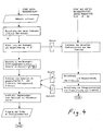
- Fig. 4 is a simplified flow diagram for the method according to the invention.
- an engine 2 in the present case a diesel engine, or the associated vehicle
- an electronic arithmetic circuit 1 various operating variables of an engine 2, in the present case a diesel engine, or the associated vehicle are supplied to an electronic arithmetic circuit 1.
- These are primarily signals from a speed sensor 3 and an accelerator position sensor 4, furthermore, for example, an engine temperature sensor 5, a boost pressure sensor 6, etc.
- the actuator 7 is controlled via a driver stage 10 by the output signal s of the computing circuit 1.
- a Servo circuit not shown here, only indicated by dashed lines, can be provided for the actuator control (cf. DE patent application P 37 40 443).
- the signal from the speed sensor 3 is processed in a speed measuring block 11 to a speed signal n j , which is preferably measured over one combustion stroke each.
- a subsequent averaging stage 12 an integral measurement takes place, for example, via a combustion cycle, known recursive or transverse methods being used.
- Filter algorithms that can be used belong to the state of the art (eg "semiconductor circuit technology", U. Tietze, Ch. Schenk, Springer Verlag, 6th edition 1983 or “Digitale Regelsysteme", R. Isermann, Springer Verlag 1977).
- the measurement does not have to take place over a complete combustion cycle, but should be carried out over the duration of a combustion cycle, ie it can take place, for example, over the second half of the combustion cycle of a first cylinder and over the second half of the combustion cycle (stroke) of a second cylinder.
- the measuring block 11 can contain pulse formers, frequency dividers or multipliers in a known manner, taking into account the type of speed sensor 3 and the number of pulses occurring per engine revolution. Likewise, if the speed sensor 3 fails, the signal from a further speed sensor, for example the alternator of the vehicle, can be supplied to the measuring block 11, reference being made to DE-A 35 01 435 in this connection.
- the average speed signal n can be stored in a memory 13 and can be supplied on the one hand to a computer area 14 for calculating the D component of the controlled system and on the other hand to a computer area 15 for calculating the P and I components.
- a memory 16 can store the P and I components calculated in the area 15 separately or temporarily as a sum.
- a first summation point 17 serves for summing the negative D component D with the P and I components, which after a via a control line 18 from the region 14 command given to the memory 16 can be read out. Furthermore, a correction unit 19 is provided, which the speed signals n j and n are fed.
- a correction signal k is calculated from various operating parameters, with readjustment relating to individual cylinders also being possible, for which purpose the speed signal n j , which is decisive for a single combustion stroke, is required in any case.
- the correction signal k is combined with the P + I + D signal in a second summation point 20 and fed to a limiter unit 21, which is provided primarily for safety reasons (full load limitation) and to comply with specified exhaust gas values. Your output signal s is led to driver stage 10.
- a measurement interrupt is carried out, the measured speed value is read in ("IN"), then the P, I and D components are calculated, summed up and output to control the actuator (Arrow St).
- the total time between the input of the measured value and the output of the calculated value is denoted by t TOT , it actually determines the dead time of the controlled system and determines the time t MEAS between successive measurements, meaning that t MEAS > t DEAD should apply. If the measuring time is shorter than the dead time, individual measurements are pointless and the arithmetic circuit often uses "outdated" measured values.
- the invention provides a method in which the determination of the D component with higher priority is carried out separately from the determination of the P and I components. To explain this method, reference is made not only to FIG. 1 but also to FIGS. 3 and 4 below.
- a measurement interrupt is carried out at a certain point in time (arrow M j + 1 in FIG. 3a) n j + 1 is read in and stored in a memory, where it has the previous value n j replaced (Fig. 3c and memory 13 in Fig. 1).
- the calculation of the D component follows (FIG. 3a).
- P components P i-1 (FIG. 3d) or I components I i-1 (FIG. 3e) calculated beforehand and stored in memories (cf. memory 16, FIG. 1) are called up (FIG. see control line 18 of FIG. 1) and added to the calculated D component.
- the sum signal is output to control the actuator (arrow St; Fig. 3a).
- the boxes P i , I i schematically indicate the calculation of the P and I components. This calculation is carried out without temporal coupling to the D-share calculation, either when computing capacity is free, or at certain, predetermined time intervals, for example every 20 ms.
- the speed values n retrieved from the associated memory (memory 13 in FIG. 1; FIG. 3c).
- the calculated P and I components are temporarily stored (FIG. 3d, e; memory 16 in FIG. 1), so that they are available for summation with the D component at the given time.
- Fig. 3 shows that the calculation of the D component to the measurement intervals t MESS is attached, which is made possible by the separate therefrom, time-consuming calculation of the P and I components.
- the measuring time t MESS is inversely proportional to the engine speed within at least speed ranges. This means that, for example, from a certain speed, only every second pulse and at even higher speeds only every third or fourth pulse of the speed sensor can be used for the calculation, etc.
- the indices j relate to successive measuring intervals, whereas the indices i refer to the recurring P and I share calculations. 3 provides for the separate storage of the calculated P and I components. However, it is equally possible to store the sum P + I and then add it to the D component.
Landscapes
- Engineering & Computer Science (AREA)
- Chemical & Material Sciences (AREA)
- Combustion & Propulsion (AREA)
- Mechanical Engineering (AREA)
- General Engineering & Computer Science (AREA)
- Electrical Control Of Air Or Fuel Supplied To Internal-Combustion Engine (AREA)
- Combined Controls Of Internal Combustion Engines (AREA)
- Output Control And Ontrol Of Special Type Engine (AREA)
- Control Of Throttle Valves Provided In The Intake System Or In The Exhaust System (AREA)
- Control Of Velocity Or Acceleration (AREA)
Priority Applications (1)
| Application Number | Priority Date | Filing Date | Title |
|---|---|---|---|
| AT89890078T ATE67278T1 (de) | 1988-03-16 | 1989-03-16 | Verfahren zum steuern und regeln einer brennkraftmaschine eines fahrzeuges. |
Applications Claiming Priority (2)
| Application Number | Priority Date | Filing Date | Title |
|---|---|---|---|
| DE3808819A DE3808819A1 (de) | 1988-03-16 | 1988-03-16 | Verfahren zum steuern und regeln einer brennkraftmaschine eines fahrzeuges |
| DE3808819 | 1988-03-16 |
Publications (3)
| Publication Number | Publication Date |
|---|---|
| EP0333701A2 true EP0333701A2 (fr) | 1989-09-20 |
| EP0333701A3 EP0333701A3 (en) | 1990-04-11 |
| EP0333701B1 EP0333701B1 (fr) | 1991-09-11 |
Family
ID=6349893
Family Applications (1)
| Application Number | Title | Priority Date | Filing Date |
|---|---|---|---|
| EP89890078A Expired - Lifetime EP0333701B1 (fr) | 1988-03-16 | 1989-03-16 | Méthode de commande et régulation de moteur automobile |
Country Status (4)
| Country | Link |
|---|---|
| EP (1) | EP0333701B1 (fr) |
| AT (1) | ATE67278T1 (fr) |
| DE (2) | DE3808819A1 (fr) |
| ES (1) | ES2025856T3 (fr) |
Families Citing this family (1)
| Publication number | Priority date | Publication date | Assignee | Title |
|---|---|---|---|---|
| DE102020201845A1 (de) | 2020-02-14 | 2021-08-19 | Volkswagen Aktiengesellschaft | Verfahren zur Steuerung eines Verbrennungsmotors bei einem Motorstart |
Family Cites Families (6)
| Publication number | Priority date | Publication date | Assignee | Title |
|---|---|---|---|---|
| JPS5340105A (en) * | 1976-09-24 | 1978-04-12 | Nippon Denso Co Ltd | Automobile control unit |
| DE2735596C2 (de) * | 1977-08-06 | 1986-09-18 | Robert Bosch Gmbh, 7000 Stuttgart | Einrichtung zur elektronischen Einspritzmengenregelung bei Brennkraftmaschinen mit Selbstzündung |
| DE2906782A1 (de) * | 1979-02-22 | 1980-09-04 | Bosch Gmbh Robert | Einrichtung zum daempfen von ruckelschwingungen bei einer brennkraftmaschine |
| DE3329800A1 (de) * | 1983-08-18 | 1985-02-28 | Robert Bosch Gmbh, 7000 Stuttgart | Drehzahlregelsystem fuer eine brennkraftmaschine mit selbstzuendung |
| DE3501435A1 (de) * | 1985-01-17 | 1986-07-17 | Voest-Alpine Friedmann GmbH, Linz | Anordnung zum steuern und regeln einer brennkraftmaschine |
| DE3536034A1 (de) * | 1985-10-09 | 1987-04-09 | Bosch Gmbh Robert | Eingebersystem fuer einspritzduesen |
-
1988
- 1988-03-16 DE DE3808819A patent/DE3808819A1/de active Granted
-
1989
- 1989-03-16 AT AT89890078T patent/ATE67278T1/de not_active IP Right Cessation
- 1989-03-16 DE DE8989890078T patent/DE58900269D1/de not_active Expired - Fee Related
- 1989-03-16 ES ES198989890078T patent/ES2025856T3/es not_active Expired - Lifetime
- 1989-03-16 EP EP89890078A patent/EP0333701B1/fr not_active Expired - Lifetime
Also Published As
| Publication number | Publication date |
|---|---|
| ATE67278T1 (de) | 1991-09-15 |
| ES2025856T3 (es) | 1992-04-01 |
| DE3808819A1 (de) | 1989-09-28 |
| DE58900269D1 (de) | 1991-10-17 |
| EP0333701A3 (en) | 1990-04-11 |
| EP0333701B1 (fr) | 1991-09-11 |
| DE3808819C2 (fr) | 1990-06-07 |
Similar Documents
| Publication | Publication Date | Title |
|---|---|---|
| EP0416270B1 (fr) | Procédé et dispositif pour commander et régler un moteur à auto-allumage | |
| DE102008057092B4 (de) | Steuervorrichtung für einen Verbrennungsmotor | |
| DE3924923C2 (fr) | ||
| DE3015832A1 (de) | Verfahren und vorrichtung zum steuern und/oder regeln der luftmengenzufuhr bei verbrennungskraftmaschinen | |
| EP1254310B1 (fr) | Systeme de reglage d'un moteur a combustion interne | |
| DE69127030T2 (de) | Methode und Vorrichtung zur Kraftstoffeinspritzungssteuerung für eine Brennkraftmaschine | |
| DE102012100622A1 (de) | Kraftstoffeinspritzungssteuerung | |
| DE3835113A1 (de) | Elektronisches ueberwachungssystem fuer eine brennkraftmaschine mit innerer verbrennung | |
| DE102018213114A1 (de) | Verfahren und Vorrichtung zum Betreiben eines Verbrennungsmotors mit einem Common-Rail-Einspritzsystem | |
| DE69200442T2 (de) | Verfahren zur Korrektur von Steuerparametern einer Brennkraftmaschine und Vorrichtung zur Durchführung des Verfahrens. | |
| EP0347446B1 (fr) | Procede et agencement de regulation du dosage d'air dans des moteurs a combustion interne, notamment au ralenti et en deceleration | |
| EP0449851B1 (fr) | Procede de mesure de carburant | |
| DE112023004467T5 (de) | Systeme für gasförmige kraftstoffe und steuerungen | |
| DE3046863A1 (de) | Elektronisch gesteuertes kraftstoffzumesssystem fuer eine brennkraftmaschine | |
| DE3421640A1 (de) | Einrichtung zum feststellen des aenderungswertes in der drehzahl eines verbrennungsmotors | |
| DE3423110C2 (fr) | ||
| EP0385969A1 (fr) | Dispositif de commande et de régulation d'un moteur diesel | |
| EP1117930B1 (fr) | Procede de compensation electronique d'un dispositif d'injection | |
| EP0502849A1 (fr) | Systeme de commande electronique pour le dosage de carburant dans le cas d'un moteur a combustion interne. | |
| EP0333701B1 (fr) | Méthode de commande et régulation de moteur automobile | |
| DE3009627A1 (de) | Einrichtung zum ermitteln von steuer- und regelgroessen einer brennkraftmaschine | |
| DE102008005154A1 (de) | Verfahren und Vorrichtung zur Überwachung einer Motorsteuereinheit | |
| EP2019195B1 (fr) | Procédé de détermination de la quantité de carburant injectée | |
| EP0333702B1 (fr) | Méthode de commande et de contrôle de moteur automobile | |
| EP0353216B1 (fr) | Appareil de commande et régulation du moteur à combustion d'un véhicule |
Legal Events
| Date | Code | Title | Description |
|---|---|---|---|
| PUAI | Public reference made under article 153(3) epc to a published international application that has entered the european phase |
Free format text: ORIGINAL CODE: 0009012 |
|
| AK | Designated contracting states |
Kind code of ref document: A2 Designated state(s): AT CH DE ES FR GB IT LI SE |
|
| PUAL | Search report despatched |
Free format text: ORIGINAL CODE: 0009013 |
|
| AK | Designated contracting states |
Kind code of ref document: A3 Designated state(s): AT CH DE ES FR GB IT LI SE |
|
| 17P | Request for examination filed |
Effective date: 19901004 |
|
| 17Q | First examination report despatched |
Effective date: 19910225 |
|
| RAP1 | Party data changed (applicant data changed or rights of an application transferred) |
Owner name: AUTOMOTIVE DIESEL GESELLSCHAFT M.B.H. |
|
| GRAA | (expected) grant |
Free format text: ORIGINAL CODE: 0009210 |
|
| AK | Designated contracting states |
Kind code of ref document: B1 Designated state(s): AT CH DE ES FR GB IT LI SE |
|
| REF | Corresponds to: |
Ref document number: 67278 Country of ref document: AT Date of ref document: 19910915 Kind code of ref document: T |
|
| REF | Corresponds to: |
Ref document number: 58900269 Country of ref document: DE Date of ref document: 19911017 |
|
| GBT | Gb: translation of ep patent filed (gb section 77(6)(a)/1977) | ||
| ITF | It: translation for a ep patent filed | ||
| ET | Fr: translation filed | ||
| REG | Reference to a national code |
Ref country code: ES Ref legal event code: FG2A Ref document number: 2025856 Country of ref document: ES Kind code of ref document: T3 |
|
| PLBE | No opposition filed within time limit |
Free format text: ORIGINAL CODE: 0009261 |
|
| STAA | Information on the status of an ep patent application or granted ep patent |
Free format text: STATUS: NO OPPOSITION FILED WITHIN TIME LIMIT |
|
| 26N | No opposition filed | ||
| EAL | Se: european patent in force in sweden |
Ref document number: 89890078.2 |
|
| PGFP | Annual fee paid to national office [announced via postgrant information from national office to epo] |
Ref country code: GB Payment date: 19970213 Year of fee payment: 9 |
|
| PGFP | Annual fee paid to national office [announced via postgrant information from national office to epo] |
Ref country code: FR Payment date: 19970214 Year of fee payment: 9 |
|
| PGFP | Annual fee paid to national office [announced via postgrant information from national office to epo] |
Ref country code: DE Payment date: 19970220 Year of fee payment: 9 Ref country code: AT Payment date: 19970220 Year of fee payment: 9 |
|
| PGFP | Annual fee paid to national office [announced via postgrant information from national office to epo] |
Ref country code: SE Payment date: 19970221 Year of fee payment: 9 |
|
| PGFP | Annual fee paid to national office [announced via postgrant information from national office to epo] |
Ref country code: CH Payment date: 19970226 Year of fee payment: 9 |
|
| PGFP | Annual fee paid to national office [announced via postgrant information from national office to epo] |
Ref country code: ES Payment date: 19970321 Year of fee payment: 9 |
|
| PG25 | Lapsed in a contracting state [announced via postgrant information from national office to epo] |
Ref country code: GB Free format text: LAPSE BECAUSE OF NON-PAYMENT OF DUE FEES Effective date: 19980316 Ref country code: AT Free format text: LAPSE BECAUSE OF NON-PAYMENT OF DUE FEES Effective date: 19980316 |
|
| PG25 | Lapsed in a contracting state [announced via postgrant information from national office to epo] |
Ref country code: SE Free format text: LAPSE BECAUSE OF NON-PAYMENT OF DUE FEES Effective date: 19980317 Ref country code: ES Free format text: LAPSE BECAUSE OF EXPIRATION OF PROTECTION Effective date: 19980317 |
|
| PG25 | Lapsed in a contracting state [announced via postgrant information from national office to epo] |
Ref country code: LI Free format text: LAPSE BECAUSE OF NON-PAYMENT OF DUE FEES Effective date: 19980331 Ref country code: FR Free format text: THE PATENT HAS BEEN ANNULLED BY A DECISION OF A NATIONAL AUTHORITY Effective date: 19980331 Ref country code: CH Free format text: LAPSE BECAUSE OF NON-PAYMENT OF DUE FEES Effective date: 19980331 |
|
| GBPC | Gb: european patent ceased through non-payment of renewal fee |
Effective date: 19980316 |
|
| REG | Reference to a national code |
Ref country code: CH Ref legal event code: PL |
|
| PG25 | Lapsed in a contracting state [announced via postgrant information from national office to epo] |
Ref country code: DE Free format text: LAPSE BECAUSE OF NON-PAYMENT OF DUE FEES Effective date: 19981201 |
|
| EUG | Se: european patent has lapsed |
Ref document number: 89890078.2 |
|
| REG | Reference to a national code |
Ref country code: FR Ref legal event code: ST |
|
| REG | Reference to a national code |
Ref country code: ES Ref legal event code: FD2A Effective date: 20000601 |
|
| PG25 | Lapsed in a contracting state [announced via postgrant information from national office to epo] |
Ref country code: IT Free format text: LAPSE BECAUSE OF NON-PAYMENT OF DUE FEES;WARNING: LAPSES OF ITALIAN PATENTS WITH EFFECTIVE DATE BEFORE 2007 MAY HAVE OCCURRED AT ANY TIME BEFORE 2007. THE CORRECT EFFECTIVE DATE MAY BE DIFFERENT FROM THE ONE RECORDED. Effective date: 20050316 |