EP0333702A2 - Method for controlling and regulating an automotive engine - Google Patents
Method for controlling and regulating an automotive engine Download PDFInfo
- Publication number
- EP0333702A2 EP0333702A2 EP89890079A EP89890079A EP0333702A2 EP 0333702 A2 EP0333702 A2 EP 0333702A2 EP 89890079 A EP89890079 A EP 89890079A EP 89890079 A EP89890079 A EP 89890079A EP 0333702 A2 EP0333702 A2 EP 0333702A2
- Authority
- EP
- European Patent Office
- Prior art keywords
- speed
- engine
- ist
- component
- difference
- Prior art date
- Legal status (The legal status is an assumption and is not a legal conclusion. Google has not performed a legal analysis and makes no representation as to the accuracy of the status listed.)
- Granted
Links
- 238000000034 method Methods 0.000 title claims abstract description 16
- 230000001276 controlling effect Effects 0.000 title claims description 4
- 230000001105 regulatory effect Effects 0.000 title claims description 4
- 239000000446 fuel Substances 0.000 claims abstract description 4
- 238000002347 injection Methods 0.000 claims abstract description 4
- 239000007924 injection Substances 0.000 claims abstract description 4
- 238000002485 combustion reaction Methods 0.000 claims description 11
- 230000015654 memory Effects 0.000 claims description 9
- 230000006870 function Effects 0.000 claims description 5
- 238000001514 detection method Methods 0.000 claims 1
- 230000015572 biosynthetic process Effects 0.000 abstract description 6
- 230000008859 change Effects 0.000 description 3
- 238000010586 diagram Methods 0.000 description 3
- 230000010354 integration Effects 0.000 description 3
- 230000006399 behavior Effects 0.000 description 2
- 238000004364 calculation method Methods 0.000 description 2
- 230000001419 dependent effect Effects 0.000 description 2
- 230000004069 differentiation Effects 0.000 description 2
- 238000005259 measurement Methods 0.000 description 2
- 230000008569 process Effects 0.000 description 2
- 238000006243 chemical reaction Methods 0.000 description 1
- 238000001914 filtration Methods 0.000 description 1
- 238000012986 modification Methods 0.000 description 1
- 230000004048 modification Effects 0.000 description 1
- 230000000737 periodic effect Effects 0.000 description 1
- 239000004065 semiconductor Substances 0.000 description 1
- 239000000243 solution Substances 0.000 description 1
- 230000007704 transition Effects 0.000 description 1
Images

Classifications
-
- F—MECHANICAL ENGINEERING; LIGHTING; HEATING; WEAPONS; BLASTING
- F02—COMBUSTION ENGINES; HOT-GAS OR COMBUSTION-PRODUCT ENGINE PLANTS
- F02D—CONTROLLING COMBUSTION ENGINES
- F02D31/00—Use of speed-sensing governors to control combustion engines, not otherwise provided for
- F02D31/001—Electric control of rotation speed
- F02D31/007—Electric control of rotation speed controlling fuel supply
-
- F—MECHANICAL ENGINEERING; LIGHTING; HEATING; WEAPONS; BLASTING
- F02—COMBUSTION ENGINES; HOT-GAS OR COMBUSTION-PRODUCT ENGINE PLANTS
- F02D—CONTROLLING COMBUSTION ENGINES
- F02D41/00—Electrical control of supply of combustible mixture or its constituents
- F02D41/30—Controlling fuel injection
- F02D41/38—Controlling fuel injection of the high pressure type
- F02D41/40—Controlling fuel injection of the high pressure type with means for controlling injection timing or duration
- F02D41/406—Electrically controlling a diesel injection pump
- F02D41/407—Electrically controlling a diesel injection pump of the in-line type
-
- F—MECHANICAL ENGINEERING; LIGHTING; HEATING; WEAPONS; BLASTING
- F02—COMBUSTION ENGINES; HOT-GAS OR COMBUSTION-PRODUCT ENGINE PLANTS
- F02B—INTERNAL-COMBUSTION PISTON ENGINES; COMBUSTION ENGINES IN GENERAL
- F02B3/00—Engines characterised by air compression and subsequent fuel addition
- F02B3/06—Engines characterised by air compression and subsequent fuel addition with compression ignition
-
- F—MECHANICAL ENGINEERING; LIGHTING; HEATING; WEAPONS; BLASTING
- F02—COMBUSTION ENGINES; HOT-GAS OR COMBUSTION-PRODUCT ENGINE PLANTS
- F02D—CONTROLLING COMBUSTION ENGINES
- F02D41/00—Electrical control of supply of combustible mixture or its constituents
- F02D41/02—Circuit arrangements for generating control signals
- F02D41/14—Introducing closed-loop corrections
- F02D41/1401—Introducing closed-loop corrections characterised by the control or regulation method
- F02D2041/1409—Introducing closed-loop corrections characterised by the control or regulation method using at least a proportional, integral or derivative controller
-
- F—MECHANICAL ENGINEERING; LIGHTING; HEATING; WEAPONS; BLASTING
- F02—COMBUSTION ENGINES; HOT-GAS OR COMBUSTION-PRODUCT ENGINE PLANTS
- F02D—CONTROLLING COMBUSTION ENGINES
- F02D41/00—Electrical control of supply of combustible mixture or its constituents
- F02D41/02—Circuit arrangements for generating control signals
- F02D41/14—Introducing closed-loop corrections
- F02D41/1401—Introducing closed-loop corrections characterised by the control or regulation method
- F02D2041/1413—Controller structures or design
- F02D2041/1422—Variable gain or coefficients
-
- Y—GENERAL TAGGING OF NEW TECHNOLOGICAL DEVELOPMENTS; GENERAL TAGGING OF CROSS-SECTIONAL TECHNOLOGIES SPANNING OVER SEVERAL SECTIONS OF THE IPC; TECHNICAL SUBJECTS COVERED BY FORMER USPC CROSS-REFERENCE ART COLLECTIONS [XRACs] AND DIGESTS
- Y02—TECHNOLOGIES OR APPLICATIONS FOR MITIGATION OR ADAPTATION AGAINST CLIMATE CHANGE
- Y02T—CLIMATE CHANGE MITIGATION TECHNOLOGIES RELATED TO TRANSPORTATION
- Y02T10/00—Road transport of goods or passengers
- Y02T10/10—Internal combustion engine [ICE] based vehicles
- Y02T10/40—Engine management systems
Definitions
- the invention relates to a method for controlling and regulating the internal combustion engine of a motor vehicle, in which an output signal is calculated in a computing device as a function of operating variable signals, such as the speed, the accelerator pedal position, the engine temperature, and this is used to control an electromechanical actuator for the fuel - and / or amount of air, e.g. B. the injection pump of a diesel engine is used, the P, I and D components of a speed control signal are determined separately and then added, and to a device for performing this method.
- an output signal is calculated in a computing device as a function of operating variable signals, such as the speed, the accelerator pedal position, the engine temperature, and this is used to control an electromechanical actuator for the fuel - and / or amount of air, e.g. B.
- the injection pump of a diesel engine is used, the P, I and D components of a speed control signal are determined separately and then added, and to a device for performing this method.
- Electronic controllers of motor vehicle internal combustion engines are supplied with the engine speed in the form of a speed signal as the most important control variable, in addition to other variables.
- an output signal is calculated, usually taking into account stored characteristic curve fields, which is electromechanically applied to an actuator in a diesel engine, e.g. the control rod of the injection pump or the quantity actuator of pump nozzles acts.
- such a controller generally has a PID characteristic with a proportional, integral and differential component (hereinafter only briefly referred to as P, I and D component), the influences of these components on the behavior of a controlled system are known to the person skilled in the art and are not discussed here in detail.
- P, I and D component a proportional, integral and differential component
- the regulation of an internal combustion engine poses particular problems that should be taken into account when designing a control method or controller.
- the dynamics of the engine are speed-dependent. Therefore, even in certain operating situations, such as engaging at low speed, disengaging and accelerating, etc., a high D component of the control is desirable so that load change reactions can occur quickly can be compensated. In other work areas, especially in those in which the vehicle tends to jerky vibrations, the D component must be lower.
- the aim of the invention is to provide a method and a device which enables the D component of the speed control to be determined in a manner which is as simple and reliable as possible to suit the circumstances of an internal combustion engine for a motor vehicle, in particular a diesel engine.
- an electronic computing circuit 1 different operating variables of a motor 2, in the present Case of a diesel engine or the associated vehicle supplied. These are primarily signals from a speed sensor 3 and an accelerator pedal position sensor 4, furthermore, for example, an engine temperature sensor 5, etc. the position of the actuator 6 representative output signal r is fed back to the computing circuit 1.
- the actuator 6 is controlled via a driver stage 9 by the output signal s of the computing circuit 1.
- a servo circuit (not shown here, only indicated by dashed lines) can be provided for actuating the actuator (cf. DE patent application P 37 40 443).
- Fig. 2 shows a section of the arithmetic circuit 1.
- the output signal of the speed sensor 3 is processed in a speed measuring block 10 and optionally in a filter 11 to a speed signal n is processed.
- the measuring block 10 can contain pulse formers, frequency dividers or multipliers in a known manner, taking into account the type of speed sensor 3 and the number of pulses occurring per engine revolution.
- the signal from a further speed sensor for example the alternator of the vehicle, can be supplied to the measuring block 10, reference being made to DE-OS 35 01 435 in this connection.
- the speed signal thus obtained is n a PID controller block 12 is supplied to the desired size as is to the target speed n detected signal in the arithmetic circuit 1 is supplied.
- the signal n should depend on the accelerator pedal sensor 5 and various other operating parameters of the engine 2.
- Fig. 3 shows in general form that the P, I and D components are calculated separately according to the desired control characteristic.
- the integration takes place, for example, by adding up in a memory 15 at cycle times T 1 with the aid of a summation point 16 and a controlled switch 17 and multiplication by a constant factor K I in a multiplier 18.
- a memory 19 For this purpose, according to the prior art, a memory 19, a controlled switch 20, a summation point 21, a multiplier 22 for the multiplication by 1 / T 2 and a multiplier 23 for the multiplication by a constant factor K D are used .
- Gl- (6) can also be written as
- the factor "60" occurs when the speed is measured in rpm.
- K n results from the formation of the difference quotient where T2 is the latest and T2 'the previous measurement.
- the duration T2 is variable according to the engine speed (see. Eq. 9).
- n is from this stored value to the subsequent clock instant the current average speed value subtracted and then the obtained difference with a multiply constant factor K Do .n o / K n .
- the speed signal n is obtained in the speed measuring block 10 with a possibly downstream filter 11, the measuring block 10 also providing the clock signal T2.
- this signal could also be derived from a further speed sensor, which scans the corresponding marks on a rotating part of the motor 2.
- the circuit in its branches relevant for obtaining the P and I components is completely the same as in FIG. 3 and the same reference numerals are used for the same elements.
- the D component of the rotational speed signal n, n of the respective preceding speed signal ' is taken off, including a summing junction 25, a controlled by the clock T2 switch 26 and a memory 27, as shown, is used.
- the obtained difference is multiplied in a multiplier 28 by the constant factor K Do .n o / K n, is such that according to equation (16) receives the D component, the combined in the summing junction 24 with the P and the I component becomes.
- a further memory 29 or register will be provided (shown in broken lines), which is used to store the current speed values and which, like the memory 27, can be controlled by a computer clock T.
- the signal n should generally depend on various operating variables that change slowly with respect to the speed, it can be regarded as constant for the present purposes.
- the speed control signal s n obtained naturally depends also on these variables from, so that the signal s n usually the output signal represents s the computing circuit immediately.
- control device can also be implemented in an analog manner
- the arithmetic circuit will generally contain one or more microcomputers and corresponding memories and the arithmetic circuit will be implemented in software.
- the hyperbolic weighting enables the D component of the controller to be adapted in a simple manner to the dynamic behavior of the engine, in particular a diesel engine or the engine-motor vehicle system. Compared to the unweighted, i.e. here speed-independent determination of the D-portion surprisingly results in a simplification of the control device by eliminating the division by the time intervals T2.
- FIG. 7 explains a flow chart of the determination of the actuator control signal, starting from a speed pulse, the first part of equation 15 being decisive.
- the signal from the speed sensor consists of pulses which occur at times T20, T21 ...., so that the pulse distance T2 follows from the difference T21 - T20, the reciprocal of which is proportional to the actual speed.
- the pulses are fed to a counter that constantly counts up and releases at a fixed frequency, e.g. with their leading edge, an interrupt.
- the current counter status is stored in register A and the counter is reset. This reset must be done so quickly that no pulse is lost. However, it is also possible not to reset the counter and to let it continue to run, relative values being used for the further calculation.
- the value 1 / T 2 ' obtained from the previous work cycle is brought from a further register B into a register C which thus contains the value 1 / T 2' .
- the reciprocal is formed from the current value T2 (in register A) and loaded into register B.
- the contents of registers B and C are transferred to the arithmetic unit and the difference 1 / T 2 ' - 1 / T2 is formed and then with the constant factor K Do. No multiplied.
- the D component obtained in this way is finally summed up with the separately calculated (not described in detail here) D and I components, so that the actuator control signal is obtained. This process is repeated cyclically as described above with new T2 values.
Landscapes
- Engineering & Computer Science (AREA)
- Chemical & Material Sciences (AREA)
- Combustion & Propulsion (AREA)
- Mechanical Engineering (AREA)
- General Engineering & Computer Science (AREA)
- Electrical Control Of Air Or Fuel Supplied To Internal-Combustion Engine (AREA)
- Combined Controls Of Internal Combustion Engines (AREA)
- Control Of Vehicle Engines Or Engines For Specific Uses (AREA)
- Control Of Throttle Valves Provided In The Intake System Or In The Exhaust System (AREA)
Abstract
Description
Die Erfindung bezieht sich auf ein Verfahren zum Steuern und Regeln der Brennkraftmaschine eines Kraftfahrzeuges, bei welchem in Abhängigkeit von Betriebsgrößensignalen, wie der Drehzahl, der Gaspedalstellung, der Motortemperatur etc. in einer Recheneinrichtung ein Ausgangssignal errechnet und dieses zur Steuerung eines elektromechanischen Stellgliedes für die Kraftstoff- und/oder Luftmenge, z. B. der Einspritzpumpe eines Dieselmotors herangezogen wird, wobei die P-, I- und D-Anteile eines Drehzahlregelsignales getrennt ermittelt und sodann addiert werden sowie auf eine Einrichtung zur Durchführung dieses Verfahrens.The invention relates to a method for controlling and regulating the internal combustion engine of a motor vehicle, in which an output signal is calculated in a computing device as a function of operating variable signals, such as the speed, the accelerator pedal position, the engine temperature, and this is used to control an electromechanical actuator for the fuel - and / or amount of air, e.g. B. the injection pump of a diesel engine is used, the P, I and D components of a speed control signal are determined separately and then added, and to a device for performing this method.
Elektronischen Reglern von Kraftfahrzeug-Brennkraftmaschinen, insbesondere von Dieselmotoren wird neben anderen Größen als wichtigste Regelgröße die Motordrehzahl in Form eines Drehzahlsignals zugeführt. In Abhängigkeit von den zugeführten Größen wird, meist unter Berücksichtigung abgespeicherter Kennlinienfelder, ein Ausgangssignal berechnet, welches elektromechanisch auf ein Stellglied, bei einem Dieselmotor, z.B. die Regel stange der Einspritzpumpe oder das Mengenstellglied von Pumpedüsen einwirkt.Electronic controllers of motor vehicle internal combustion engines, in particular of diesel engines, are supplied with the engine speed in the form of a speed signal as the most important control variable, in addition to other variables. Depending on the quantities supplied, an output signal is calculated, usually taking into account stored characteristic curve fields, which is electromechanically applied to an actuator in a diesel engine, e.g. the control rod of the injection pump or the quantity actuator of pump nozzles acts.
Ein solcher Regler weist im allgemeinen bezüglich der Drehzahlregelung eine PID-Charakteristik mit einem Proportional-, Integral- und Differentialanteil (im folgenden nur kurz P-, I- und D-Anteil genannt) auf, wobei die Einflüsse dieser Anteile auf das Verhalten einer Regelstrecke dem Fachmann bekannt sind und hier nicht im Detail erörtert werden.Regarding the speed control, such a controller generally has a PID characteristic with a proportional, integral and differential component (hereinafter only briefly referred to as P, I and D component), the influences of these components on the behavior of a controlled system are known to the person skilled in the art and are not discussed here in detail.
Die Regelung einer Brennkraftmaschine wirft besondere Probleme auf, die bei der Konzeption eines Regelverfahrens bzw. Reglers berücksichtigt werden sollten. Insbesondere ist die Dynamik des Motors drehzahlabhängig. Daher ist auch in gewissen Betriebssituationen, z.B. Einkuppeln bei niedriger Drehzahl, Auskuppeln und Gaswegnehmen etc. ein hoher D-Anteil der Regelung erwünscht, damit Lastwechselreaktionen rasch ausgeglichen werden können. In anderen Arbeitsbereichen, insbesondere in jenen, in welchen das Fahrzeug zu Ruckelschwingungen neigt, muß der D-Anteil geringer sein.The regulation of an internal combustion engine poses particular problems that should be taken into account when designing a control method or controller. In particular, the dynamics of the engine are speed-dependent. Therefore, even in certain operating situations, such as engaging at low speed, disengaging and accelerating, etc., a high D component of the control is desirable so that load change reactions can occur quickly can be compensated. In other work areas, especially in those in which the vehicle tends to jerky vibrations, the D component must be lower.
Es wäre möglich, den D-Anteil in Abhängigkeit von der Drehzahl in einem Speicher des Reglers als Kennfeld abzulegen. Auf diese Weise könnten beliebige Funktionen D(n) festgelegt werden, doch ist das Arbeiten unter Verwendung eines solchen Speichers sehr rechenintensiv, sodaß hohe Kosten bzw. unerwünscht lange Rechenzeiten die Folge sind.It would be possible to store the D component as a function of the speed in a memory of the controller. In this way, any functions D (n) could be defined, but working using such a memory is very computationally intensive, so that high costs or undesirably long computing times are the result.
Ziel der Erfindung ist die Schaffung eines Verfahrens sowie einer Einrichtung, das in möglichst einfacher und zuverlässiger Weise eine den Gegebenheiten einer Brennkraftmaschine für ein Kraftfahrzeug, insbesondere eines Dieselmotors angepaßte Ermittlung des D-Anteils der Drehzahlregelung ermöglicht.The aim of the invention is to provide a method and a device which enables the D component of the speed control to be determined in a manner which is as simple and reliable as possible to suit the circumstances of an internal combustion engine for a motor vehicle, in particular a diesel engine.
Dieses Ziel läßt sich mit einem Verfahren nach Patentanspruch 1 und einer Einrichtung nach Patentanspruch 5 erreichen, wobei bevorzugte Modifikationen in den Unteransprüchen gekennzeichnet sind.This aim can be achieved with a method according to
Die Erfindung samt ihren weiteren Vorteilen ist im folgenden an Hand einer beispielsweisen Ausführungsform unter Bezugnahme auf die Zeichnung näher erläutert, in welcher zeigen:
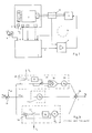
- Fig. 1 und Fig 2 in einem Prinzipschema die Regelung einer Brennkraftmaschine unter Zuhilfenahme einer Rechenschaltung,
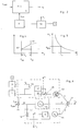
- Fig. 3 einen Teil einer Rechenschaltung nach dem Stand der Technik,
- Fig. 4 ein Diagramm zur Erläuterung der Berechnung des D-Anteils,
- Fig. 5 in einem Diagramm die erfindungsgemäße Gewichtung des D-Anteils,
- Fig. 6 einen Teil einer Rechenschaltung, die zur erfindungsgemäßen Ermittlung des D-Anteils heranziehbar ist und
- Fig. 7 an Hand eines Flußdiagramms die Ermittlung des D-Anteils.
- 1 and 2 in a schematic diagram the control of an internal combustion engine with the aid of a computing circuit,
- 3 shows a part of a computing circuit according to the prior art,
- 4 shows a diagram to explain the calculation of the D component,
- 5 shows the weighting of the D component according to the invention in a diagram,
- 6 shows a part of a computing circuit which can be used to determine the D component according to the invention, and
- Fig. 7 with the aid of a flow chart the determination of the D component.
Gemäß Fig. 1 werden einer elektronischen Rechenschaltung 1 verschiedene Betriebsgrößen eines Motors 2, im vorliegenden Fall eines Dieselmotors bzw. des zugehörigen Fahrzeuges zugeführt. Es handelt sich dabei in erster Linie um Signale eines Drehzahlgebers 3 und eines Gaspedalstellungssensors 4, weiters z.B. eines Motortemperatursensors 5 usw. Ein elektromechanisches Stellglied 6, beispielsweise ein auf das Mengenstellglied einer Verteilereinspritzpumpe 7 wirkender Stellmagnet, ist mechanisch mit einem Rückmelder 8 verbunden, dessen für die Stellung des Stellgliedes 6 repräsentatives Ausgangssignal r an die Rechenschaltung 1 zurückgeführt wird. Das Stellglied 6 wird über eine Treiberstufe 9 von dem Ausgangssignal s der Rechenschaltung 1 angesteuert. In bekannter Weise kann ein hier nicht gezeigter, nur strichliert angedeuteter Servokreis für die Stellgliedansteuerung vorgesehen sein (vgl. DE-Patentanmeldung P 37 40 443).1, an
Fig. 2 zeigt einen Ausschnitt der Rechenschaltung 1. Das Ausgangssignal des Drehzahlgebers 3 wird in einem Drehzahlmeßblock 10 und gegebenenfalls in einem Filter 11 zu einem Drehzahlsignal nist verarbeitet. Der Meßblock 10 kann in bekannter Weise Impulsformer, Frequenzteiler oder -vervielfacher enthalten, wobei auf die Art des Drehzahlgebers 3 und die Anzahl der pro Motorumdrehung anfallenden Impulse Rücksicht zu nehmen ist. Ebenso kann bei Ausfall des Drehzahlgebers 3 dem Meßblock 10 das Signal eines weiteren Drehzahlgebers, z.B. der Lichtmaschine des Fahrzeuges zugeführt werden, wobei in diesem Zusammenhang auf die DE-OS 35 01 435 verwiesen wird.Fig. 2 shows a section of the
Das so erhaltene Drehzahlsignal nist wird einem PID-Reglerblock 12 zugeführt, der als Sollgröße das in der Rechenschaltung 1 ermittelte Solldrehzahlsignal nsoll zugeführt wird. In bekannter Weise wird das Signal nsoll von dem Gaspedalsensor 5 und verschiedenen anderen Betriebsparametern des Motors 2 abhängen. In dem PID-Reglerblock 12 wird sodann das Drehzahlregelsignal sn ermittelt, das sich ganz allgemein als
sn = P + I + D (1)
anschreiben läßt.The speed signal thus obtained is n a
s n = P + I + D (1)
can write to.
Fig. 3 zeigt in allgemeiner Form, daß der P-, I- und D-Anteil entsprechend der gewünschten Regelcharakteristik getrennt errechnet werden.Fig. 3 shows in general form that the P, I and D components are calculated separately according to the desired control characteristic.
Einem Summenpunkt 13 wird das durch die Rechenschaltung 1 vorgegebene Solldrehzahlsignal nsoll sowie das Istdrehzahlsignal nist zugeführt, um die Differenz
Δn = nsoll - nist (2)
zu bilden.A
Δn = n should - n is (2)
to build.
Der Proportionalanteil ergibt sich durch einfache Multiplikation mit einem Faktor Kp in einem Multiplikator 14
P = Δn.Kp (3)The proportional component results from simple multiplication by a factor K p in a
P = Δn.K p (3)
Die Ermittlung des Integralanteiles I erfolgt durch Integration über die Zeit und Multiplikation mit einem Faktor KI
I = KI . ∫ Δn dt (4)The integral component I is determined by integration over time and multiplication by a factor K I
I = K I. ∫ Δn dt (4)
Hiebei erfolgt die Integration beispielsweise durch Aufsummieren in einem Speicher 15 zu Taktzeiten T₁ unter Zuhilfenahme eines Summenpunktes 16 und eines gesteuerten Schalters 17 sowie eine Multiplikation mit einem konstanten Faktor KI in einem Multiplikator 18. Ähnlich erfolgt die Bildung des Differentialanteils D

Hiezu dienen nach dem Stand der Technik ein Speicher 19, ein gesteuerter Schalter 20, ein Summenpunkt 21, ein Multiplikator 22 für die Multiplikation mit 1/T₂ und ein Multiplikator 23 für die Multiplikation mit einem konstanten Faktor KD.For this purpose, according to the prior art, a
Die drei auf diese Weise erhaltenen Anteile P, I und D werden schließlich in einem Summenpunkt 24 zu dem Drehzahlregelsignal sn addiert.The three components P, I and D obtained in this way are finally added to the speed control signal s n in a
Bedeuten n′ die Drehzahl zu einer Zeit T₂₀ und n die Drehzahl zum drauf folgenden Zeitpunkt T₂₁, wobei dies sinngemäß auch für Δ n′ und Δ n (siehe Fig. 3) gilt, so ist
wegen Δ n = nsoll - nist (2)
und Δ n′ = nsoll - nist (2′)
Δ n - n′ = -nist +nist′ (7)
d.h. die Summenbildung im Summenpunkt 13 ist für die Differentiation ohne Bedeutung und die Differentiation bzw. Differenzbildung kann in gleicher Weise von n oder Δ n ausgehen. Hiebei ist eine entsprechend langsame Änderung von nsoll vorausgesetzt, sodaß annähernd nsoll = const. gilt.Mean n 'the speed at a time T₂₀ and n the speed at the following time T₂₁, which also applies analogously to Δ n' and Δ n (see Fig. 3)
because Δ n = n should - n is (2)
and Δ n ′ = n should - n is (2 ′)
Δ n - n ′ = -n is + n is ′ (7)
ie the sum formation in the
Mit Gl-(7) läßt sich Gl-(6) somit auch anschreiben als
Da die Motordrehzahl auf Grund der Verbrennungstakte periodischen Schwankungen unterworfen ist, geht man von einer über einen Verbrennungszyklus (Drehwinkel α, Zeitdauer T₂) gemittelten Drehzahl
Bei einem 6-Zylindermotor z.B. wird α = 120°.With a 6-cylinder engine e.g. becomes α = 120 °.
Es gilt somit
α =
und
α =
and
Der Faktor "60" tritt auf, wenn die Drehzahl in Upm gemessen wird. Mit Einführung des Skalierungsfaktors Kn 

Die erfindungsgemäße Lösung sieht nun eine hyperbolische Gewichtung des D-Anteils vor:
Es erfolgt somit ein Übergang von einem konstanten Faktor KD zu einem hyperbolisch von der Drehzahl abhängigen Faktor KD(n), wie in Fig. 5 dargestellt. no ist eine gewählte Bezugsdrehzahl, beispielsweise no = 1000 Upm.There is thus a transition from a constant factor K D to a hyperbolic speed-dependent factor K D (n), as shown in FIG. 5. n o is a selected reference speed, for example n o = 1000 rpm.
Die Einführung der hyperbolischen Gewichtung führt daher zu
Das Verfahren nach der Erfindung reduziert sich somit in überraschend einfacher Weise darauf, zur Ermittlung des D-Anteils jeweils einen mittleren Drehzahlwert n′ist abzuspeichern, von diesem gespeicherten Wert zum darauffolgenden Taktzeitpunkt den aktuellen mittleren Drehzahlwert nist abzuziehen und sodann die erhaltene Differenz mit einem konstanten Faktor KDo.no/Kn zu multiplizieren. Die entsprechende Prinzipschaltung, die im allgemeinen in der Rechenschaltung 1 softwaremäßig realisiert ist, ist in Fig. 6 dargestellt und nachfolgend beschrieben. Wie im Zusammenhang mit Fig. 2 bereits beschrieben, wird in dem Drehzahlmeßblock 10 mit einem allenfalls nachgeschalteten Filter 11 das Drehzahlsignal nist gewonnen, wobei der Meßblock 10 auch das Taktsignal T₂ liefert. Dieses Signal könnte aber auch von einem weiteren Drehzahlgeber, der entsprechenden Marken an einem sich drehenden Teil des Motors 2 abtastet, hergeleitet sein.The method of the invention is thus reduced in a surprisingly simple manner to, for determining the D-portion of each n has an average speed value is to be stored ', n is from this stored value to the subsequent clock instant the current average speed value subtracted and then the obtained difference with a multiply constant factor K Do .n o / K n . The corresponding basic circuit, which is generally used in the
Die Schaltung gleicht in ihren für die Gewinnung des P- und I-Anteils maßgeblichen Zweigen völlig jener nach Fig. 3 und für gleiche Elemente werden gleiche Bezugszeichen verwendet.The circuit in its branches relevant for obtaining the P and I components is completely the same as in FIG. 3 and the same reference numerals are used for the same elements.
Für die nach dem erfindungsgemäßen Verfahren durchgeführte Bildung des D-Anteils wird das Drehzahlsignal nist von dem jeweils vorgehenden Drehzahlsignal n′ist abgezogen, wozu ein Summenpunkt 25, ein vom Takt T₂ gesteuerter Schalter 26 sowie ein Speicher 27, wie dargestellt, verwendet werden. Die erhaltene Differenz wird in einem Multiplikator 28 mit dem konstanten Faktor KDo.no/Kn multipliziert, sodaß man nach Gleichung (16) den D-Anteil erhält, der in dem Summenpunkt 24 mit dem P- und dem I-Anteil vereinigt wird. Im allgemeinen wird noch ein weiterer Speicher 29 oder Register vorgesehen sein (strichliert gezeichnet), der zur Speicherung der aktuellen Drehzahlwerte dient und der, ebenso wie der Speicher 27, von einem Rechnertakt T steuerbar ist.For the processing performed by the inventive process form the D component of the rotational speed signal n, n of the respective preceding speed signal 'is taken off, including a summing
Da das Signal nsoll im allgemeinen von verschiedenen, sich gegenüber der Drehzahl langsam ändernden Betriebsgrößen abhängt, kann es für die vorliegenden Zwecke als konstant angesehen werden. Das gewonnene Drehzahlregelsignal sn hängt natürlich gleichfalls von diesen Größen ab, sodaß das Signal sn meist das Ausgangssignal s der Rechenschaltung unmittelbar darstellt.Since the signal n should generally depend on various operating variables that change slowly with respect to the speed, it can be regarded as constant for the present purposes. The speed control signal s n obtained naturally depends also on these variables from, so that the signal s n usually the output signal represents s the computing circuit immediately.
Die Steuereinrichtung nach der Erfindung kann zwar auch in analoger Weise realisiert werden, doch wird die Rechenschaltung im allgemeinen ein oder mehrere Mikrorechner sowie entsprechende Speicher enthalten und die Rechenschaltung wird softwaremäßig realisiert sein.Although the control device according to the invention can also be implemented in an analog manner, the arithmetic circuit will generally contain one or more microcomputers and corresponding memories and the arithmetic circuit will be implemented in software.
Die Erfindung ermöglicht durch die hyperbolische Gewichtung in einfacher Weise die Anpassung des D-Anteiles des Reglers an das dynamische Verhalten des Motors, insbesondere eines Dieselmotors bzw. des Systems Motor-Kraftfahrzeug. Im Vergleich zu der ungewichteten, d.h. hier drehzahlunabhängigen Ermittlung des D-Anteiles ergibt sich in überraschender Weise eine Vereinfachung der Steuereinrichtung durch Fortfall der Division durch die Zeitintervalle T₂.The hyperbolic weighting enables the D component of the controller to be adapted in a simple manner to the dynamic behavior of the engine, in particular a diesel engine or the engine-motor vehicle system. Compared to the unweighted, i.e. here speed-independent determination of the D-portion surprisingly results in a simplification of the control device by eliminating the division by the time intervals T₂.
In Fig. 7 ist einem Flußdiagramm die Ermittlung des Stellgliedansteuersignales, ausgehend von einem Drehzahlpuls erläutert, wobei der erste Teil der Gleichung 15 maßgeblich ist. Das Signal des Drehzahlgebers besteht aus Impulsen, die zu Zeiten T₂₀, T₂₁.... auftreten, sodaß aus der Differenz T₂₁ - T₂₀ der Impulsabstand T₂ folgt, dessen Kehrwert der Ist-Drehzahl proportional ist.FIG. 7 explains a flow chart of the determination of the actuator control signal, starting from a speed pulse, the first part of
Die Pulse werden einem Zähler zugeführt, der ständig mit fester Frequenz hochzählt und lösen, z.B. mit ihrer Vorderflanke, einen Interrupt aus. Der momentane Zählerstand wird in ein Register A abgelegt und der Zähler wird rückgesetzt. Diese Rücksetzung muß so schnell erfolgen, daß kein Impuls verlorengeht. Es ist aber auch möglich, den Zähler nicht rückzusetzen und ihn weiterlaufen zu lassen, wobei zur weiteren Berechnung Relativwerte verwendet werden.The pulses are fed to a counter that constantly counts up and releases at a fixed frequency, e.g. with their leading edge, an interrupt. The current counter status is stored in register A and the counter is reset. This reset must be done so quickly that no pulse is lost. However, it is also possible not to reset the counter and to let it continue to run, relative values being used for the further calculation.
Bevor der Wert T₂ weiterverarbeitet wird, wird aus einem weiteren Register B der aus dem vorhergehenden Arbeitszyklus erhaltene Wert 1/T2′ in ein Register C gebracht, das somit den Wert 1/T2′ enthält.Before the value T₂ is processed further, the
Aus dem aktuellen Wert T₂ (im Register A) wird der Kehrwert gebildet und in das Register B geladen. Die Inhalte der Register B und C werden in das Rechenwerk übertragen und es wird die Differenz 1/T2′ - 1/T₂ gebildet und darauffolgend mit dem konstanten Faktor KDo . No multipliziert. Der so erhaltene D-Anteil wird schließlich mit den getrennt errechneten (hier nicht im Detail beschrieben) D- und I-Anteilen aufsummiert, sodaß man das Stellgliedansteuersignal erhält. Dieser Vorgang wiederholt sich wie oben beschrieben mit jeweils neuen T₂-Werten zyklisch.The reciprocal is formed from the current value T₂ (in register A) and loaded into register B. The contents of registers B and C are transferred to the arithmetic unit and the
Da Störsignale bzw. Meßunsicherheiten in der Praxis auftreten, kann es zweckmäßig sein, die erhaltenen T₂ bzw. 1/T₂-Werte einer Filterung zu unterziehen, die nach bekannten Rekursiv- oder Transversalalgorithmen durchgeführt werden kann. Solche Filteralgorithmen gehören dem Stand der Technik an (z. B. "Halbleiterschaltungstechnik" U. Tietze, Ch. Schenk, Springer Verlag, 6. Auflage 1983 oder "Digitale Regelsysteme", R. Isermann, Springer Verlag 1977).Since interference signals or measurement uncertainties occur in practice, it may be expedient to subject the T₂ or 1 / T₂ values obtained to filtering, which can be carried out according to known recursive or transverse algorithms. Such filter algorithms belong to the state of the art (eg "semiconductor circuit technology" U. Tietze, Ch. Schenk, Springer Verlag, 6th edition 1983 or "Digitale Regelsysteme", R. Isermann, Springer Verlag 1977).
Claims (6)
Priority Applications (1)
| Application Number | Priority Date | Filing Date | Title |
|---|---|---|---|
| AT89890079T ATE100901T1 (en) | 1988-03-16 | 1989-03-16 | METHOD FOR CONTROLLING AND REGULATING THE ENGINE OF A MOTOR VEHICLE. |
Applications Claiming Priority (2)
| Application Number | Priority Date | Filing Date | Title |
|---|---|---|---|
| DE3808820A DE3808820A1 (en) | 1988-03-16 | 1988-03-16 | METHOD FOR CONTROLLING AND REGULATING THE INTERNAL COMBUSTION ENGINE OF A MOTOR VEHICLE |
| DE3808820 | 1988-03-16 |
Publications (3)
| Publication Number | Publication Date |
|---|---|
| EP0333702A2 true EP0333702A2 (en) | 1989-09-20 |
| EP0333702A3 EP0333702A3 (en) | 1990-04-11 |
| EP0333702B1 EP0333702B1 (en) | 1994-01-26 |
Family
ID=6349894
Family Applications (1)
| Application Number | Title | Priority Date | Filing Date |
|---|---|---|---|
| EP89890079A Expired - Lifetime EP0333702B1 (en) | 1988-03-16 | 1989-03-16 | Method for controlling and regulating an automotive engine |
Country Status (4)
| Country | Link |
|---|---|
| EP (1) | EP0333702B1 (en) |
| AT (1) | ATE100901T1 (en) |
| DE (2) | DE3808820A1 (en) |
| ES (1) | ES2049847T3 (en) |
Cited By (6)
| Publication number | Priority date | Publication date | Assignee | Title |
|---|---|---|---|---|
| FR2678025A1 (en) * | 1991-06-21 | 1992-12-24 | Bosch Gmbh Robert | METHOD AND DEVICE FOR CONTROLLING A FUEL FILLING SYSTEM CONTROLLED BY A SOLENOID VALVE, IN PARTICULAR FOR AN INTERNAL COMBUSTION DIESEL ENGINE. |
| WO1995027237A1 (en) * | 1994-04-01 | 1995-10-12 | Asia Motors Co., Inc. | Device for controlling accelerator pedal of vehicle |
| GB2314944A (en) * | 1996-07-02 | 1998-01-14 | Daimler Benz Ag | Controlling fuel injection in an internal combustion engine |
| EP0936354A3 (en) * | 1998-02-10 | 2001-08-08 | DEUTZ Aktiengesellschaft | Electronic control device |
| EP2860378A1 (en) * | 2013-09-18 | 2015-04-15 | Kabushiki Kaisha Toyota Jidoshokki | Vehicle speed control apparatus of industrial vehicle |
| CN107975477A (en) * | 2017-11-20 | 2018-05-01 | 北京航天长征飞行器研究所 | An automatic control method and system for a diesel engine-driven ultra-large flow vacuum pump |
Family Cites Families (6)
| Publication number | Priority date | Publication date | Assignee | Title |
|---|---|---|---|---|
| JPS59203850A (en) * | 1983-05-04 | 1984-11-19 | Diesel Kiki Co Ltd | Apparatus for controlling engine speed |
| DE3329800A1 (en) * | 1983-08-18 | 1985-02-28 | Robert Bosch Gmbh, 7000 Stuttgart | SPEED CONTROL SYSTEM FOR AN INTERNAL COMBUSTION ENGINE |
| JPS6181545A (en) * | 1984-09-28 | 1986-04-25 | Honda Motor Co Ltd | Fuel supply control method for internal combustion engine |
| DE3501435A1 (en) * | 1985-01-17 | 1986-07-17 | Voest-Alpine Friedmann GmbH, Linz | ARRANGEMENT FOR CONTROLLING AND REGULATING AN INTERNAL COMBUSTION ENGINE |
| DE3536034A1 (en) * | 1985-10-09 | 1987-04-09 | Bosch Gmbh Robert | INPUT SYSTEM FOR INJECTION NOZZLES |
| DE3730443A1 (en) * | 1987-09-10 | 1989-03-23 | Voest Alpine Automotive | METHOD FOR CONTROLLING AND REGULATING AN INTERNAL COMBUSTION ENGINE AND ELECTRONIC FUEL INJECTION DEVICE FOR CARRYING OUT THE METHOD |
-
1988
- 1988-03-16 DE DE3808820A patent/DE3808820A1/en active Granted
-
1989
- 1989-03-16 EP EP89890079A patent/EP0333702B1/en not_active Expired - Lifetime
- 1989-03-16 DE DE89890079T patent/DE58906795D1/en not_active Expired - Fee Related
- 1989-03-16 ES ES89890079T patent/ES2049847T3/en not_active Expired - Lifetime
- 1989-03-16 AT AT89890079T patent/ATE100901T1/en not_active IP Right Cessation
Cited By (10)
| Publication number | Priority date | Publication date | Assignee | Title |
|---|---|---|---|---|
| FR2678025A1 (en) * | 1991-06-21 | 1992-12-24 | Bosch Gmbh Robert | METHOD AND DEVICE FOR CONTROLLING A FUEL FILLING SYSTEM CONTROLLED BY A SOLENOID VALVE, IN PARTICULAR FOR AN INTERNAL COMBUSTION DIESEL ENGINE. |
| WO1995027237A1 (en) * | 1994-04-01 | 1995-10-12 | Asia Motors Co., Inc. | Device for controlling accelerator pedal of vehicle |
| GB2314944A (en) * | 1996-07-02 | 1998-01-14 | Daimler Benz Ag | Controlling fuel injection in an internal combustion engine |
| GB2314944B (en) * | 1996-07-02 | 1998-09-09 | Daimler Benz Ag | Method for controlling the injection quantity of fuel fed to an internal combustion engine |
| EP0936354A3 (en) * | 1998-02-10 | 2001-08-08 | DEUTZ Aktiengesellschaft | Electronic control device |
| EP2860378A1 (en) * | 2013-09-18 | 2015-04-15 | Kabushiki Kaisha Toyota Jidoshokki | Vehicle speed control apparatus of industrial vehicle |
| AU2014224089B2 (en) * | 2013-09-18 | 2016-03-17 | Kabushiki Kaisha Toyota Jidoshokki | Vehicle speed control apparatus of industrial vehicle |
| US9897018B2 (en) | 2013-09-18 | 2018-02-20 | Kabushiki Kaisha Toyota Jidoshokki | Vehicle speed control apparatus of industrial vehicle |
| CN107975477A (en) * | 2017-11-20 | 2018-05-01 | 北京航天长征飞行器研究所 | An automatic control method and system for a diesel engine-driven ultra-large flow vacuum pump |
| CN107975477B (en) * | 2017-11-20 | 2019-06-18 | 北京航天长征飞行器研究所 | A method and system for automatic control of a diesel engine-driven super-flow vacuum pump |
Also Published As
| Publication number | Publication date |
|---|---|
| DE3808820A1 (en) | 1989-09-28 |
| DE3808820C2 (en) | 1991-06-06 |
| ATE100901T1 (en) | 1994-02-15 |
| EP0333702B1 (en) | 1994-01-26 |
| DE58906795D1 (en) | 1994-03-10 |
| EP0333702A3 (en) | 1990-04-11 |
| ES2049847T3 (en) | 1994-05-01 |
Similar Documents
| Publication | Publication Date | Title |
|---|---|---|
| DE3010583C2 (en) | Method for controlling the fuel supply, in particular fuel injection, to an internal combustion engine | |
| DE69300959T2 (en) | Method for predicting air flow in a cylinder. | |
| DE3874585T2 (en) | METHOD FOR PRECALCULATING THE PARAMETERS FOR CONTROLLING THE FUEL SUPPLY FOR AN INTERNAL COMBUSTION ENGINE. | |
| DE2749369C2 (en) | Control system for an actuator in the additional air supply bypass duct of a throttle valve in internal combustion engines | |
| DE69902992T2 (en) | DEVICE FOR ESTIMATING THE AIR / FUEL RATIO FOR A FUEL INJECTION SYSTEM OF AN INTERNAL COMBUSTION ENGINE | |
| DE69200899T2 (en) | Device for regulating the speed of an internal combustion engine. | |
| DE3221640A1 (en) | METHOD AND DEVICE FOR THE OPTIMAL CONTROL OF INTERNAL COMBUSTION ENGINES | |
| DE3242795A1 (en) | DEVICE FOR CORRECTING THE AIR / FUEL RATIO FOR AN INTERNAL COMBUSTION ENGINE DEPENDING ON THE SUCTION TEMPERATURE | |
| DE3421640C2 (en) | ||
| DE3644639C2 (en) | ||
| DE3725521C2 (en) | ||
| EP0333702B1 (en) | Method for controlling and regulating an automotive engine | |
| DE3226026A1 (en) | METHOD AND DEVICE FOR THE ELECTRONIC CONTROL OF AN INTERNAL COMBUSTION ENGINE | |
| EP2550443B1 (en) | Method and apparatus for adapting adaptation values for actuating injection valves in an engine system having a plurality of injection types | |
| EP0502849B1 (en) | Electronic fuel-supply control system for an internal-combustion engine | |
| DE4037772A1 (en) | METHOD AND DEVICE FOR IDLE CONTROL OF AN INTERNAL COMBUSTION ENGINE | |
| DE19603091C1 (en) | Method for controlling a controlled system, in particular an internal combustion engine | |
| EP0707685B1 (en) | Method of adapting internal-combustion engine air values from a substitute characteristic diagram used to control, on the occurrence of pulsing in the air-aspiration line, the formation of the mixture to suit the currently prevailing outside-air conditions | |
| EP0894187B1 (en) | Process for model-based nonstationary control of an internal combustion engine | |
| DE102014213547B4 (en) | Electronic control unit for an internal combustion engine | |
| EP0175162A2 (en) | Electronic apparatus for generating an electrical fuel-measuring signal for a combustion engine | |
| WO1989009334A1 (en) | Learning control process and device for internal combustion engines | |
| DE3525393C2 (en) | ||
| WO1991017350A1 (en) | Process and device for determining the amount of fuel to be supplied to an internal-combustion engine with intermittent fuel injection during operation | |
| DE68901822T2 (en) | METHOD FOR REGULATING THE FUEL / AIR RATIO OF A MIXTURE SUPPLIED TO A COMBUSTION ENGINE WITHOUT PHYSICAL MEASUREMENT OF THE FUEL / AIR RATIO. |
Legal Events
| Date | Code | Title | Description |
|---|---|---|---|
| PUAI | Public reference made under article 153(3) epc to a published international application that has entered the european phase |
Free format text: ORIGINAL CODE: 0009012 |
|
| AK | Designated contracting states |
Kind code of ref document: A2 Designated state(s): AT CH DE ES FR GB IT LI SE |
|
| PUAL | Search report despatched |
Free format text: ORIGINAL CODE: 0009013 |
|
| AK | Designated contracting states |
Kind code of ref document: A3 Designated state(s): AT CH DE ES FR GB IT LI SE |
|
| 17P | Request for examination filed |
Effective date: 19901004 |
|
| 17Q | First examination report despatched |
Effective date: 19920325 |
|
| RAP1 | Party data changed (applicant data changed or rights of an application transferred) |
Owner name: ROBERT BOSCH AKTIENGESELLSCHAFT |
|
| GRAA | (expected) grant |
Free format text: ORIGINAL CODE: 0009210 |
|
| AK | Designated contracting states |
Kind code of ref document: B1 Designated state(s): AT CH DE ES FR GB IT LI SE |
|
| REF | Corresponds to: |
Ref document number: 100901 Country of ref document: AT Date of ref document: 19940215 Kind code of ref document: T |
|
| GBT | Gb: translation of ep patent filed (gb section 77(6)(a)/1977) |
Effective date: 19940126 |
|
| ET | Fr: translation filed | ||
| REF | Corresponds to: |
Ref document number: 58906795 Country of ref document: DE Date of ref document: 19940310 |
|
| ITF | It: translation for a ep patent filed | ||
| REG | Reference to a national code |
Ref country code: ES Ref legal event code: FG2A Ref document number: 2049847 Country of ref document: ES Kind code of ref document: T3 |
|
| PLBE | No opposition filed within time limit |
Free format text: ORIGINAL CODE: 0009261 |
|
| STAA | Information on the status of an ep patent application or granted ep patent |
Free format text: STATUS: NO OPPOSITION FILED WITHIN TIME LIMIT |
|
| 26N | No opposition filed | ||
| EAL | Se: european patent in force in sweden |
Ref document number: 89890079.0 |
|
| PGFP | Annual fee paid to national office [announced via postgrant information from national office to epo] |
Ref country code: GB Payment date: 19970213 Year of fee payment: 9 |
|
| PGFP | Annual fee paid to national office [announced via postgrant information from national office to epo] |
Ref country code: FR Payment date: 19970214 Year of fee payment: 9 |
|
| PGFP | Annual fee paid to national office [announced via postgrant information from national office to epo] |
Ref country code: DE Payment date: 19970220 Year of fee payment: 9 Ref country code: AT Payment date: 19970220 Year of fee payment: 9 |
|
| PGFP | Annual fee paid to national office [announced via postgrant information from national office to epo] |
Ref country code: SE Payment date: 19970221 Year of fee payment: 9 |
|
| PGFP | Annual fee paid to national office [announced via postgrant information from national office to epo] |
Ref country code: CH Payment date: 19970226 Year of fee payment: 9 |
|
| PGFP | Annual fee paid to national office [announced via postgrant information from national office to epo] |
Ref country code: ES Payment date: 19970321 Year of fee payment: 9 |
|
| PG25 | Lapsed in a contracting state [announced via postgrant information from national office to epo] |
Ref country code: GB Free format text: LAPSE BECAUSE OF NON-PAYMENT OF DUE FEES Effective date: 19980316 Ref country code: AT Free format text: LAPSE BECAUSE OF NON-PAYMENT OF DUE FEES Effective date: 19980316 |
|
| PG25 | Lapsed in a contracting state [announced via postgrant information from national office to epo] |
Ref country code: SE Free format text: LAPSE BECAUSE OF NON-PAYMENT OF DUE FEES Effective date: 19980317 Ref country code: ES Free format text: LAPSE BECAUSE OF NON-PAYMENT OF DUE FEES Effective date: 19980317 |
|
| PG25 | Lapsed in a contracting state [announced via postgrant information from national office to epo] |
Ref country code: LI Free format text: LAPSE BECAUSE OF NON-PAYMENT OF DUE FEES Effective date: 19980331 Ref country code: FR Free format text: THE PATENT HAS BEEN ANNULLED BY A DECISION OF A NATIONAL AUTHORITY Effective date: 19980331 Ref country code: CH Free format text: LAPSE BECAUSE OF NON-PAYMENT OF DUE FEES Effective date: 19980331 |
|
| GBPC | Gb: european patent ceased through non-payment of renewal fee |
Effective date: 19980316 |
|
| REG | Reference to a national code |
Ref country code: CH Ref legal event code: PL |
|
| PG25 | Lapsed in a contracting state [announced via postgrant information from national office to epo] |
Ref country code: DE Free format text: LAPSE BECAUSE OF NON-PAYMENT OF DUE FEES Effective date: 19981201 |
|
| EUG | Se: european patent has lapsed |
Ref document number: 89890079.0 |
|
| REG | Reference to a national code |
Ref country code: FR Ref legal event code: ST |
|
| REG | Reference to a national code |
Ref country code: ES Ref legal event code: FD2A Effective date: 20000503 |
|
| PG25 | Lapsed in a contracting state [announced via postgrant information from national office to epo] |
Ref country code: IT Free format text: LAPSE BECAUSE OF NON-PAYMENT OF DUE FEES;WARNING: LAPSES OF ITALIAN PATENTS WITH EFFECTIVE DATE BEFORE 2007 MAY HAVE OCCURRED AT ANY TIME BEFORE 2007. THE CORRECT EFFECTIVE DATE MAY BE DIFFERENT FROM THE ONE RECORDED. Effective date: 20050316 |