EP0334157A2 - Système implantable de dérivation et sa méthode d'assemblage - Google Patents
Système implantable de dérivation et sa méthode d'assemblage Download PDFInfo
- Publication number
- EP0334157A2 EP0334157A2 EP89104441A EP89104441A EP0334157A2 EP 0334157 A2 EP0334157 A2 EP 0334157A2 EP 89104441 A EP89104441 A EP 89104441A EP 89104441 A EP89104441 A EP 89104441A EP 0334157 A2 EP0334157 A2 EP 0334157A2
- Authority
- EP
- European Patent Office
- Prior art keywords
- valve
- base
- outlet
- flow control
- inlet
- Prior art date
- Legal status (The legal status is an assumption and is not a legal conclusion. Google has not performed a legal analysis and makes no representation as to the accuracy of the status listed.)
- Granted
Links
- 238000000034 method Methods 0.000 title claims abstract description 14
- 239000012528 membrane Substances 0.000 claims abstract description 132
- 239000012530 fluid Substances 0.000 claims abstract description 114
- 239000003814 drug Substances 0.000 claims abstract description 23
- 229940079593 drug Drugs 0.000 claims abstract description 23
- 238000002347 injection Methods 0.000 claims abstract description 19
- 239000007924 injection Substances 0.000 claims abstract description 19
- 239000000463 material Substances 0.000 claims description 21
- 238000011010 flushing procedure Methods 0.000 claims description 10
- 239000004743 Polypropylene Substances 0.000 claims description 8
- -1 polypropylene Polymers 0.000 claims description 8
- 229920001155 polypropylene Polymers 0.000 claims description 8
- 229920001971 elastomer Polymers 0.000 claims description 5
- 239000000806 elastomer Substances 0.000 claims description 5
- 230000000717 retained effect Effects 0.000 claims description 5
- 239000000853 adhesive Substances 0.000 claims description 4
- 230000001070 adhesive effect Effects 0.000 claims description 4
- 238000004891 communication Methods 0.000 claims description 3
- 230000005465 channeling Effects 0.000 claims 3
- 230000002093 peripheral effect Effects 0.000 claims 2
- 230000037361 pathway Effects 0.000 claims 1
- 238000007789 sealing Methods 0.000 claims 1
- 238000005086 pumping Methods 0.000 abstract description 2
- 210000001124 body fluid Anatomy 0.000 abstract 1
- 239000010839 body fluid Substances 0.000 abstract 1
- 239000002991 molded plastic Substances 0.000 abstract 1
- 210000004556 brain Anatomy 0.000 description 12
- 210000001175 cerebrospinal fluid Anatomy 0.000 description 8
- 239000000969 carrier Substances 0.000 description 5
- 239000002184 metal Substances 0.000 description 5
- 229920002379 silicone rubber Polymers 0.000 description 5
- 210000003625 skull Anatomy 0.000 description 5
- 210000001519 tissue Anatomy 0.000 description 4
- 230000002861 ventricular Effects 0.000 description 4
- 230000008901 benefit Effects 0.000 description 3
- 238000010276 construction Methods 0.000 description 3
- 230000000694 effects Effects 0.000 description 3
- 210000002837 heart atrium Anatomy 0.000 description 3
- 208000003906 hydrocephalus Diseases 0.000 description 3
- 238000004519 manufacturing process Methods 0.000 description 3
- 230000002829 reductive effect Effects 0.000 description 3
- 230000002441 reversible effect Effects 0.000 description 3
- 241001354471 Pseudobahia Species 0.000 description 2
- 230000004888 barrier function Effects 0.000 description 2
- 238000003780 insertion Methods 0.000 description 2
- 230000037431 insertion Effects 0.000 description 2
- 230000005855 radiation Effects 0.000 description 2
- 238000003325 tomography Methods 0.000 description 2
- 238000009825 accumulation Methods 0.000 description 1
- 239000008280 blood Substances 0.000 description 1
- 210000004369 blood Anatomy 0.000 description 1
- 229940000425 combination drug Drugs 0.000 description 1
- 230000007423 decrease Effects 0.000 description 1
- 230000003247 decreasing effect Effects 0.000 description 1
- 230000000881 depressing effect Effects 0.000 description 1
- 238000013461 design Methods 0.000 description 1
- 238000009792 diffusion process Methods 0.000 description 1
- 230000007613 environmental effect Effects 0.000 description 1
- 230000002452 interceptive effect Effects 0.000 description 1
- 210000004731 jugular vein Anatomy 0.000 description 1
- 238000012423 maintenance Methods 0.000 description 1
- 230000007257 malfunction Effects 0.000 description 1
- 239000007769 metal material Substances 0.000 description 1
- 238000012986 modification Methods 0.000 description 1
- 230000004048 modification Effects 0.000 description 1
- 239000013618 particulate matter Substances 0.000 description 1
- 239000002861 polymer material Substances 0.000 description 1
- 229920001059 synthetic polymer Polymers 0.000 description 1
- 238000011144 upstream manufacturing Methods 0.000 description 1
- 230000002792 vascular Effects 0.000 description 1
Images

Classifications
-
- A—HUMAN NECESSITIES
- A61—MEDICAL OR VETERINARY SCIENCE; HYGIENE
- A61M—DEVICES FOR INTRODUCING MEDIA INTO, OR ONTO, THE BODY; DEVICES FOR TRANSDUCING BODY MEDIA OR FOR TAKING MEDIA FROM THE BODY; DEVICES FOR PRODUCING OR ENDING SLEEP OR STUPOR
- A61M27/00—Drainage appliance for wounds or the like, i.e. wound drains, implanted drains
- A61M27/002—Implant devices for drainage of body fluids from one part of the body to another
- A61M27/006—Cerebrospinal drainage; Accessories therefor, e.g. valves
-
- F—MECHANICAL ENGINEERING; LIGHTING; HEATING; WEAPONS; BLASTING
- F16—ENGINEERING ELEMENTS AND UNITS; GENERAL MEASURES FOR PRODUCING AND MAINTAINING EFFECTIVE FUNCTIONING OF MACHINES OR INSTALLATIONS; THERMAL INSULATION IN GENERAL
- F16K—VALVES; TAPS; COCKS; ACTUATING-FLOATS; DEVICES FOR VENTING OR AERATING
- F16K15/00—Check valves
- F16K15/14—Check valves with flexible valve members
- F16K15/148—Check valves with flexible valve members the closure elements being fixed in their centre
-
- Y—GENERAL TAGGING OF NEW TECHNOLOGICAL DEVELOPMENTS; GENERAL TAGGING OF CROSS-SECTIONAL TECHNOLOGIES SPANNING OVER SEVERAL SECTIONS OF THE IPC; TECHNICAL SUBJECTS COVERED BY FORMER USPC CROSS-REFERENCE ART COLLECTIONS [XRACs] AND DIGESTS
- Y10—TECHNICAL SUBJECTS COVERED BY FORMER USPC
- Y10T—TECHNICAL SUBJECTS COVERED BY FORMER US CLASSIFICATION
- Y10T137/00—Fluid handling
- Y10T137/7722—Line condition change responsive valves
- Y10T137/7837—Direct response valves [i.e., check valve type]
- Y10T137/7879—Resilient material valve
- Y10T137/7888—With valve member flexing about securement
- Y10T137/789—Central mount
Definitions
- This invention relates generally to surgically implanted shunt systems and related flow control valves. More particularly, this invention relates to shunt systems including one-way flow control valves for controlling the flow of cerebrospinal fluid out of a brain ventricle and preventing back flow of fluid into the brain ventricle.
- cerebrospinal fluid accumulated in the brain ventricles is drained away by a catheter inserted into the ventricle through the skull, and the catheter is connected to a tube which conducts the fluid away from the brain to be reintroduced into the vascular system, as by extending through the patient's jugular vein to the atrium portion of the heart.
- a pump or valve is placed in the conduit between the brain and the heart.
- an antechamber as a component of a shunt system between the ventricular catheter and the flow control valve.
- Such placement of an antechamber as a component of the shunt system enables a physician to inject medication into the shunt system at a convenient location for flushing either distally or proximally.
- One problem relates to the unintended obstruction of the free flow of fluid from the ventricular catheter through the antechamber to the flow control valve.
- the positioning of a needle shield within an antechamber often presents the possibility that the antechamber can itself become occluded or become obstructed, and present a barrier in the drainage system.
- Another problem presented in prior antechambers is that after initial contact is made between the end of a needle and the needle shield, slight forces exerted on the needle may cause its tip to slide off the needle shield and, unknowingly, pass through the antechamber. This can lead to the injection of medication into the tissue surrounding the antechamber, rather than within the antechamber itself.
- a shunt system which includes an antechamber wherein medication can be injected between the ventricular cathether and the flow control valve, which antechamber provides means for effectively positioning the end of a needle within the injection chamber and yet is of such a construction that the unobstructed flow of fluid through the injection chamber is assured.
- a shunt system of controlling the flow of fluids from one part of the human body to another which is constructed substantially of non-metallic materials and provides trouble-free and reliable operation in use.
- the system is relatively inexpensive to manufacture, and can be easily modified to provide a variety of pressure/flow characteristics.
- the shunt system preferably includes antechamber means for injecting medication into the shunt system, and a multiple-membrane flow control valve for controlling the flow of fluid from one portion of the human body to another.
- the flow control valve includes a pair of relatively rigid bases which are invested within a relatively flexible encasement.
- Each base includes an outer housing and a valve membrane carrier securely positioned within the outer housing.
- the bases define inlet/outlet fluid passageways, and are positioned within the encasement such that the encasement defines an intermediate fluid passageway between the inlet/outlet fluid passageways. Further, the encasement is deformable by external pressure to facilitate manual flushing of the valve.
- a flow control member is attached to each base to control the flow of fluid through the valve.
- Each flow control member includes a rigid central support or nail, and an arch-like flexible resilient membrane. The central support is attached to the respective valve membrane carrier and extends therefrom to support the resilient membrane over the outlet side of the valve membrane carrier.
- a first flow control member attached to the base adjacent the inlet is positioned with respect to a valve seat on the first base to normally permit free fluid flow through the inlet fluid passageway. It is further positioned, however, so that upon deformation of the encasement to flush the valve, the membrane temporarily contacts the adjacent valve seat in a manner to occlude the inlet fluid passageway.
- a second flow control member on the other hand, is attached to the base adjacent the outlet.
- This second flow control member positions its resiliently biased membrane to contact a valve seat on the second base in a manner normally occluding the outlet fluid passageway, but selectively opens to permit controlled unidirectional flow therethrough.
- Such valve construction normally prevents flow of fluid through the valve, but permits fluid flow through the valve when the upstream fluid pressure exceeds the downstream fluid pressure by a predetermined amount.
- the flow control valve of the preferred embodiment can be provided with different resilient membranes of varying thicknesses.
- the resistance to flow through the valve increases with an increase in membrane thickness.
- the bases are preferably formed of polypropylene material and the membranes are preferably formed of a silicone elastomer material.
- the flexible encasement which cooperates with the bases to form an intermediate fluid passageway is also preferably molded of a silicone elastomer material.
- the base adjacent to the inlet preferably includes a relatively rigid recess in which the membrane is positioned to protect it against deformation when the flexible encasement is manually manipulated.
- the base adjacent the outlet includes a non-deformable outlet chamber in which the membrane is positioned.
- the valve membrane carriers each define a plurality of fluid flow apertures of channels which are collectively covered by the adjacent flow control member.
- the antechamber means includes, generally, a rigid needle shield situated within a relatively flexible encasement or housing.
- the needle shield has a dog bone-like cross-section, and the ends of the needle shield are contoured to permit its abutment against the antechamber encasement without occluding the openings therethrough.
- the dog bone-like cross-section of the needle shield helps to prevent a tip of a needle from slipping off the needle shield during injection of medication into the shunt system.
- tubing is attached to each base by sliding an end of the tubing into the base, placing a grommet into the end of the tubing to expand the end thereof, and then pulling the tubing in a second direction away from the base.
- the expanded end of the tubing engages the base in a secure manner to form a frictional attachment.
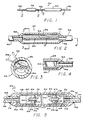
- FIG. 1 The drawings show a surgically implantable shunt system generally designated in Fig. 1 by the reference number 20.
- This improved shunt system 20 includes, broadly, an antechamber 22 and a multiple-membrane flow control valve 24, which are connected by segments of surgical tubing 26, 28 and 30 to drain fluids from one portion of the human body to another.
- the antechamber 22 and the flow control valve 24 form portions of a fluid conduit extending from a proximal catheter (not shown), which is inserted through the skull into a brain ventricle containing cerebrospinal fluid under pressure, to a distal catheter (also not shown), which serves to discharge cerebrospinal fluid into, for example, the atrium portion of a patient's heart.
- the shunt system provides a highly reliable valve designed to prevent valve seat deformation and membrane to valve seat sticking.
- the shunt system of the present invention is inexpensive to produce, and the use of metal as a functional component has been eliminated. Moreover, positioning concerns relating to the valve have been minimized through the provision of a cylindrical design. Thus, due to the symmetry of the system, there is no top or bottom which must be anchored in place over the patient's skull for proper operation.
- the antechamber 22 includes a flexible, generally cylindrical encasement or housing 32 and a relatively rigid needle shield 34 positioned within the housing 32.
- the housing 32 includes openings at each end for receiving ends of tubing sections 26 and 28.
- the housing 32 is secured to the tubing sections 26 and 28 by a suitable adhesive.
- the needle shield 34 is preferably constructed of a polypropylene material to form a plate 36 having a dog bone-like cross-section (see FIG. 3).
- a polypropylene material is preferred for the needle shield 34 in order to minimize any potential sticking between the housing 32, which is preferably constructed of a silicone elastomer material, and the needle shield.
- the dog bone-like cross-section of the needle shield 34 helps to prevent a tip of a needle 38 from slipping off the needle shield during injection of medication into the shunt system 20.
- the needle shield 34 is further provided contoured ends 40, which permit the needle shield to abut adjacent the ends of the connecting tubing 26 and 28, without occluding them. This feature helps assure a user of the shunt system 20 that the flow of fluid through the components thereof will not be unintentionally obstructed.
- the housing 32 of the antechamber 22 can be punctured by the needle 38 in order to inject medication into the shunt system 20.
- the silicone elastomer material of the housing 32 has a sufficient thickness to permit insertion of a twenty-five gauge or smaller needle 38 without affecting the ability of the housing to reseal after needle has been withdrawn.
- the polypropylene material of the needle shield 34 has sufficient rigidity to prevent the needle 38 inserted through the housing 32 from passing all the way through the antechamber 22. This permits the physician to feel where the tip of the needle 38 is positioned during injection, to insure that the medication is being injected into the shunt system 20 and not into the surrounding tissue.
- the antechamber 22 can then be used as a pump for directing the medication toward the proximal catheter or toward the flow control valve 24.
- the physician simply depresses the section of surgical tubing 28 between the antechamber 22 and the valve 24 through manual percutaneous pressure, and then depresses the housing 32 of the antechamber to flush the contents thereof through the proximal section of the surgical tubing 26.
- the medication within the antechamber 22 can be pumped distally toward the valve 24. This is accomplished by percutaneously occluding the proximal surgical tubing 26, and then depressing the housing 32 to flush medication therein through the intermediate section of surgical tubing 28 to the valve 24.
- the flow control valve 24 includes a first base 42 positioned adjacent an inlet 74 of the valve, and a second base 44 positioned adjacent an outlet 76 of the valve. These bases 42 and 44 are invested within a flexible encasement 46.
- the first base 42 includes a first outer housing 48, and a first valve membrane carrier 50 securely positioned within the first outer housing.
- the first valve membrane carrier 50 provides a cylindrical support for a first flow control member 52, and is press-fit within a support portion 54 provided by the first outer housing 48.
- the second base 44 includes a second outer housing 56, and a second valve membrane carrier 58 securely positioned within the second outer housing.
- the second valve membrane carrier 58 provides a cylindrical support for a second flow control member 60, and is press-fit within a support portion 62 provided by the second outer housing 56.
- each of the valve membrane carriers 50 and 58 include a cylindrical outer portion 64 which abuts against a correspondingly shaped inner surface of the support portions 54 and 62 to form a fluid tight seal therebetween.
- a central reinforced aperture 66 is provided for receiving a portion of the respective flow control member 52 or 60, and this central aperture 66 is surrounded by three additional apertures 68 which provide a plurality of channels through which fluid is permitted to flow.
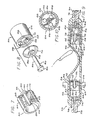
- the flow control members 52 and 60 are arranged serially within the valve 24 for controlling the flow of cerebrospinal fluid out of a brain ventricle and preventing backflow of fluid into the brain ventricle by the provision of resilient nonmetallic membranes 70 (see FIG. 8).
- the membranes 70 are molded of a synthetic polymer material different from the material of the valve membrane carriers 50 and 58, and are secured relative to the valve membrane carriers to generally cover the fluid flow apertures 68.
- the first flow control member 52 is positioned on the first valve membrane carrier 50 to normally permit free fluid flow through the inlet fluid passageway. Thus, the first flow control member 52 does not, in the preferred embodiment, limit the flow of fluid from the valve inlet to the valve outlet.
- the first flow control member 52 is positioned, however, so that upon deformation of the encasement 46 to flush the valve 24, membrane 70 will temporarily sealingly contact a first valve seat 72 provided by the first valve membrane carrier 50, in a manner to occlude the inlet fluid passageway.
- the resilient membrane 70 of the second flow control member 60 is normally biased to close communication between the inlet 74 and the outlet 76 of the valve 24, but will open to permit flow when the pressure on the proximal side of the resilient membrane 70 exceeds the pressure on the distal side by a predetermined amount. Moreover, should the pressure on the distal side of the resilient membrane 70 ever exceed the pressure on the proximal side, tending to cause flow in a reverse direction through the valve 24, the membrane 70 of the second flow control member 60 will seal tightly against a second valve seat 78 provided on the second valve membrane carrier 58. This effectively seals the fluid flow apertures 68 through the second valve membrane carrier 58, and prevents any such reverse flow through the valve 24.
- the outer housings 48 and 56, and the valve membrane carriers 50 and 58 are preferably formed of a polypropylene material, and the membranes 70 are preferably formed of an elastomer material, preferably a silicone elastomer material. Both polypropylene and elastomer materials have been shown to produce an acceptable level of tissue reaction, and the use of this particular duality of materials, in contrast to the use of only a single material, markedly decreases the change of the membranes 70 adhering to any portion of the bases 42 and 44, which would clog the drain passage and defeat the purpose of the valve 24.
- the flow control members 52 and 60 each include a rigid nail 80 having an elongated shaft 82 and an expanded head 84 at the end of the shaft.
- the nail 80 is capable of being driven into the central reinforced aperture 66 of the respective valve membrane carrier 50 and 58 to be frictionally retained therein.
- the nail is preferably constructed of polypropylene material which will not stretch or flex as the nail is being driven into the central reinforced aperture 66. After the nail is properly placed within the aperture, it is preferably heat welded to the respective valve membrane carrier 50 and 58.
- the flexible resilient membranes 70 have an arch-shape, as for example a section of a sphere, and are designed to contact the valve seats 72 and 78 generally along the outer edges of the membrane in a manner surrounding the fluid flow apertures 68.
- Each membrane 70 is secured to its respective valve membrane carrier 50 and 58 by a central support/nail 80 described above.
- Each membrane 70 is provided an aperture 86 which is surrounded by a reinforced section 88.
- the shaft 82 extends through the membrane aperture 86 so that the reinforced section 88 abuts the head 84 of the nail 80.
- the membrane is retained in place on the nail 80 by an interference fit or by use of an adhesive, or by any other suitable means.
- valve 24 of the present invention is primarily designed to provide controlled resistance to cerebrospinal fluid flow from a brain ventricle to another location in the body, such as the atrium portion of the patient's heart, it will be appreciated that a doctor must be able to select a valve having the particular pressure/flow characteristics desired for each individual application. That is, a valve which permits flow at a relatively low pressure differential may not be suitable where the maintenance of a higher pressure differential is indicated.
- the valve 24 can be provided with thick membranes or relatively thin membranes. Resistance to flow increases with the increase in membrane thickness.
- the first and second bases 42 and 44 are separated from one another within the flexible encasement 46, so that the central section of the encasement can be deformed by external pressure to facilitate manual flushing of the valve 24.
- This central portion of the encasement 46 defines an intermediate fluid passageway 90 between the inlet fluid passageway provided through the first base 42, and the outlet fluid passageway provided through the second base 44.
- the first base 42 is provided a membrane shield 92 integrally formed with the first outer housing 48, which extends outwardly from the first valve seat 72.
- This membrane shield 92 forms a recess in which the first flow control member 52 is situated.
- the second flow control member 60 is similarly protected against deformation due to percutaneous pressure, by situating the resilient membrane 70 thereof within an outlet chamber 94 provided between the second valve membrane carrier 58 and the valve outlet 76.
- the second flow control member 60 is thus completely surrounded by portions of the rigid second base 44, to completely protect it against deformation due to percutaneous manipulation of the flow control valve 24.
- an end of the second section of surgical tubing 28 is inserted through the first outer housing 48, and a grommet 96 is also placed within the end theeof.
- a friction interference fit is formed between that end of the second tubing section 28 and the first outer housing 48.
- first valve membrane carrier 50 (with the first flow control member 52 assembled thereto) is press-fit into the support portion 54 of the first outer housing 48. This completes assembly of the first base 42.
- the second valve membrane carrier 58 (with the second flow control member 60 properly fixed thereto) is press-fit into the support portion 62 of the second outer housing 56. This completes the assembly of the second base 44.
- the flexible encasement 46 is then passed over the third section of tubing 30 and stretched over the first and second bases 42 and 44.
- the first base 42 will abut against the inlet end of the encasement 46 with the second section of tubing 28 extending outwardly therefrom, and the second base 44 will abut against the outlet end of the encasement 46 with the third section of tubing 30 extending outwardly therefrom.
- the encasement 46 and the first and second bases 42 and 44 are finally fixed with respect to one another by the application of an adhesive 98 between the ends of the encasement and the outwardly extending sections of tubing 28 and 30.
- a second end of the second section of tubing 28 can be adhesively secured to the antechamber housing 32 in a conventional manner.
- the first section of tubing 26 can be secured in a conventional manner to the other end of the antechamber housing 32.
- the intermediate portion of the flexible encasement 46 is pressed downwardly (as shown by a finger in FIG. 9) to force fluid within the intermediate fluid passageway 90 through the fluid flow apertures 68 of the second valve membrane carrier 58, and past the second flow control member 60 to the valve outlet 76.
- the first flow control member 52 is positioned with respect to the first valve seat 72 so that upon an increase in pressure within the intermediate fluid passageway 90 with respect to downstream fluid pressure, the membrane 70 will seal against the first valve seat 72 and prevent retrograde flow out of the valve 24.
- the second flow control member 60 Upon withdrawal of the percutaneous pressure from the flexible encasement 46, the second flow control member 60 will again engage the second valve seat 78 of the second valve membrane carrier 58 to altogether prevent the reverse flow of fluid through the fluid flow apertures 68, and therefore the entire valve 24.
- the shunt system described provides a device by which the flow of cerebrospinal fluid out of a brain ventricle can be controlled while preventing the backflow of fluid into the brain ventricle, and by which the chance of a valve clogging the drain pressure can be greatly decreased.
- the antechamber 22 and the valve 24 can be fabricated conveniently and economically, are trouble-free and reliable in use, provide convenient flushing of the shunt system, and can be easily adapted to provide a variety of pressure/flow characteristics.
- two flow control members are provided within the valve 24, only the second flow control member 60 controls the flow of fluid from the ventricular catheter through the shunt system 20.
- the first flow control member 52 is provided, primarily, to permit the intermediate fluid passageway 90 to be flushed as percutaneous pressure is applied to the flexible encasement 46.
- the antechamber 22 includes features which help insure proper positioning of a needle within the antechamber for the injection of medication, yet the structure of the needle shield 34 is such that possible occlusion of the antechamber is minimized.
Landscapes
- Health & Medical Sciences (AREA)
- Engineering & Computer Science (AREA)
- Biomedical Technology (AREA)
- General Engineering & Computer Science (AREA)
- Animal Behavior & Ethology (AREA)
- Veterinary Medicine (AREA)
- Anesthesiology (AREA)
- Heart & Thoracic Surgery (AREA)
- Hematology (AREA)
- Life Sciences & Earth Sciences (AREA)
- Ophthalmology & Optometry (AREA)
- General Health & Medical Sciences (AREA)
- Public Health (AREA)
- Otolaryngology (AREA)
- Neurology (AREA)
- Mechanical Engineering (AREA)
- External Artificial Organs (AREA)
- Prostheses (AREA)
- Media Introduction/Drainage Providing Device (AREA)
- Electrotherapy Devices (AREA)
- Infusion, Injection, And Reservoir Apparatuses (AREA)
Applications Claiming Priority (4)
| Application Number | Priority Date | Filing Date | Title |
|---|---|---|---|
| US07/173,092 US4867740A (en) | 1988-03-24 | 1988-03-24 | Multiple-membrane flow control valve and implantable shunt system |
| US07/184,749 US4861331A (en) | 1988-03-24 | 1988-04-22 | Implantable shunt system and method of assembly |
| US173092 | 2002-06-17 | ||
| US184749 | 2002-06-28 |
Publications (3)
| Publication Number | Publication Date |
|---|---|
| EP0334157A2 true EP0334157A2 (fr) | 1989-09-27 |
| EP0334157A3 EP0334157A3 (fr) | 1991-02-06 |
| EP0334157B1 EP0334157B1 (fr) | 1997-11-26 |
Family
ID=26868774
Family Applications (1)
| Application Number | Title | Priority Date | Filing Date |
|---|---|---|---|
| EP19890104441 Expired - Lifetime EP0334157B1 (fr) | 1988-03-24 | 1989-03-13 | Système implantable de dérivation |
Country Status (8)
| Country | Link |
|---|---|
| US (1) | US4861331A (fr) |
| EP (1) | EP0334157B1 (fr) |
| JP (1) | JPH0614959B2 (fr) |
| AT (1) | ATE160507T1 (fr) |
| CA (1) | CA1295209C (fr) |
| DE (1) | DE68928455T2 (fr) |
| ES (1) | ES2109915T3 (fr) |
| GR (1) | GR3025526T3 (fr) |
Cited By (5)
| Publication number | Priority date | Publication date | Assignee | Title |
|---|---|---|---|---|
| GB2258153A (en) * | 1991-06-19 | 1993-02-03 | Richard David Ashpole | Instruments for assembling and placing csf flow control shunts |
| EP0717146A2 (fr) | 1994-12-14 | 1996-06-19 | Hercules Incorporated | Résines résistantes à l'humidité à teneur réduite en sous-produits organiques halogénés |
| FR2776742A1 (fr) * | 1998-03-30 | 1999-10-01 | Medex Sa | Perfectionnement pour valve a seuil |
| EP2221083A1 (fr) | 2009-02-20 | 2010-08-25 | Raumedic Ag | Soupape à utiliser dans une conduite pour diriger un liquide |
| DE102009043098A1 (de) * | 2009-09-25 | 2011-03-31 | Aesculap Ag | Schließventil für eine Körperflüssigkeiten führende Strömungsleitung |
Families Citing this family (31)
| Publication number | Priority date | Publication date | Assignee | Title |
|---|---|---|---|---|
| JP2710355B2 (ja) * | 1988-09-20 | 1998-02-10 | 日本ゼオン株式会社 | 医用弁装置 |
| US5154693A (en) * | 1990-05-15 | 1992-10-13 | Pudenz-Schulte Medical Research Corp. | Flow control device having selectable alternative fluid pathways |
| US5176627A (en) * | 1990-05-15 | 1993-01-05 | Pudenz-Schulte Medical Research Corporation | Implantable fluid flow control device having two-piece base, and assembly process |
| US5167615A (en) * | 1990-05-15 | 1992-12-01 | Pudenz-Schulte Medical Research Corporation | Flow control device having selectable alternative fluid pathways |
| US5387188A (en) * | 1993-05-10 | 1995-02-07 | Pudenz-Schulte Medical Research Corporation | Pulsatile flow-accommodating fluid shunt |
| US5637083A (en) * | 1996-01-19 | 1997-06-10 | Pudenz-Schulte Medical Research Corporation | Implantable adjustable fluid flow control valve |
| US6383159B1 (en) | 1998-11-10 | 2002-05-07 | Eunoe, Inc. | Devices and method for removing cerebrospinal fluids from a patient's CSF space |
| US6126628A (en) * | 1997-04-22 | 2000-10-03 | Johnson & Johnson Professional, Inc. | Fluid flow limiting device |
| US6875192B1 (en) | 1998-11-10 | 2005-04-05 | Eunoe, Inc. | Devices and methods for removing cerebrospinal fluids from a patient's CSF space |
| US7189221B2 (en) * | 1998-11-10 | 2007-03-13 | Integra Life Sciences Corporation | Methods for the treatment of a normal pressure hydrocephalus |
| US7037303B2 (en) | 2001-07-06 | 2006-05-02 | Opticon Medical, Inc. | Urinary flow control valve |
| US7025739B2 (en) * | 2001-08-09 | 2006-04-11 | Integra Lifesciences Corporation | System and method for treating elevated intracranial pressure |
| WO2003071384A2 (fr) * | 2002-02-15 | 2003-08-28 | Eunoe, Inc. | Systemes et procedes de detection et de mesure du debit dans des anastomoses lcr |
| US9694166B2 (en) | 2002-03-26 | 2017-07-04 | Medtronics Ps Medical, Inc. | Method of draining cerebrospinal fluid |
| DE202004009831U1 (de) | 2004-06-22 | 2004-08-26 | Filtertek B.V. | Rückschlagventil |
| US20060089589A1 (en) * | 2004-10-21 | 2006-04-27 | Portnoy Harold D | Resistive shunt valve |
| US8002730B2 (en) * | 2005-04-29 | 2011-08-23 | Medtronic, Inc. | Anti-thrombogenic venous shunt system and method |
| US20080082036A1 (en) * | 2006-04-25 | 2008-04-03 | Medtronic, Inc. | Cerebrospinal fluid shunt having long term anti-occlusion agent delivery |
| DE102008030942A1 (de) | 2008-07-02 | 2010-01-07 | Christoph Miethke Gmbh & Co Kg | Hirnwasserdrainagen |
| DE202009012986U1 (de) | 2009-09-25 | 2010-02-11 | Aesculap Ag | Schließventil für eine Körperflüssigkeiten führende Strömungsleitung |
| US9901707B2 (en) * | 2012-05-23 | 2018-02-27 | Integra Lifesciences Switzerland Sàrl | Catheter curvature braces and methods of using same |
| WO2014055015A1 (fr) | 2012-10-01 | 2014-04-10 | Roxhed Niclas | Dérivation de liquide céphalorachidien destinée au traitement de l'hydrocéphalie |
| CN105358207B (zh) | 2013-01-22 | 2018-12-28 | 安嫩西亚公司 | 用于分流流体的系统和方法 |
| US9050436B2 (en) | 2013-03-14 | 2015-06-09 | DePuy Synthes Products, LLC | Adjustable resistance, gravitationally activated, anti-syphon valve |
| CA3124754C (fr) | 2013-03-15 | 2023-08-15 | Children's Medical Center Corporation | Dispositif de rincage de derivation |
| US9744338B2 (en) | 2014-04-18 | 2017-08-29 | Alcyone Lifesciences, Inc. | Systems and methods for shunting fluid |
| US10283275B2 (en) | 2016-05-20 | 2019-05-07 | Greatbatch Ltd. | Feedthrough seal apparatus, system, and method |
| US10792480B2 (en) | 2016-10-13 | 2020-10-06 | Anuncia, Inc. | Shunt flushers and related methods |
| WO2021087264A1 (fr) | 2019-10-31 | 2021-05-06 | Musc Foundation For Research Development | Détection de flux de dérivation à base d'ultrasons |
| CN115400332B (zh) * | 2022-09-16 | 2024-03-12 | 吉林大学第一医院 | V-p分流术腹腔端导管腹壁外置防感染装置 |
| CN116099068B (zh) * | 2023-04-12 | 2024-01-23 | 首都医科大学宣武医院 | 一种固定牢固的脑室引流系统 |
Family Cites Families (52)
| Publication number | Priority date | Publication date | Assignee | Title |
|---|---|---|---|---|
| US2969066A (en) * | 1956-10-02 | 1961-01-24 | Holter Company | Device for draining ventricular fluid in cases of hydrocephalus |
| US3020913A (en) * | 1958-07-15 | 1962-02-13 | William T Heyer | Surgical drain |
| GB1010067A (en) * | 1962-05-28 | 1965-11-17 | Stanley Charles Wade | Improvements relating to the control of fluids |
| US3288142A (en) * | 1964-04-27 | 1966-11-29 | Hakim Salomon | Hydrocephalus shunt with spring biased one-way valves |
| US3527226A (en) * | 1966-02-03 | 1970-09-08 | Cordis Corp | Ventricular catheter with valve and pump flushing means |
| US3452757A (en) * | 1966-09-14 | 1969-07-01 | Dow Corning | Two-way flushing device for treatment of hydrocephalus |
| US3595240A (en) * | 1968-08-07 | 1971-07-27 | Alan J Mishler | Hydrocephalus shunt with two-way flushing means |
| US3566875A (en) * | 1969-05-20 | 1971-03-02 | Richard K Stoehr | Device for draining cerebrospinal fluid |
| CH496445A (de) * | 1969-07-15 | 1970-09-30 | Kuffer Francois | Rückschlagventil zum Ableiten des Liquors in das Gefässsystem oder eine Körperhöhle zur Behandlung des Hydrocephalus internus et externus |
| US3654932A (en) * | 1969-11-26 | 1972-04-11 | John B Newkirk | Surgical drain for shunting fluid |
| US3690323A (en) * | 1970-12-01 | 1972-09-12 | Us Army | Device for draining ventricular fluid in cases of hydrocephalus |
| US3683929A (en) * | 1970-12-28 | 1972-08-15 | Extracorporeal Med Spec | Device for draining cerebrospinal fluid in cases of hydrocephalus |
| US3769982A (en) * | 1971-09-24 | 1973-11-06 | R Schulte | Physiological drainage system with closure means responsive to downstream suction |
| US3758073A (en) * | 1971-10-26 | 1973-09-11 | R Schulte | Valve for physiological drainage actuable by lateral compression |
| US3924635A (en) * | 1972-08-14 | 1975-12-09 | Salomon Hakim | Ventricular shunt having a variable pressure valve |
| US3886948A (en) * | 1972-08-14 | 1975-06-03 | Hakim Co Ltd | Ventricular shunt having a variable pressure valve |
| US3827439A (en) * | 1972-10-30 | 1974-08-06 | Heyer Schulte Corp | Plug valve for physiological shunt systems |
| US3999553A (en) * | 1973-03-15 | 1976-12-28 | Bio-Medical Research, Ltd. | Bio-medical pressure control device |
| US3991768A (en) * | 1973-03-16 | 1976-11-16 | Portnoy Harold D | Shunt system resistant to overdrainage and siphoning and valve therefor |
| US3910283A (en) * | 1973-10-09 | 1975-10-07 | Harry H Leveen | Process for treatment of ascites and device to accomplish same |
| US3889687A (en) * | 1974-01-31 | 1975-06-17 | Donald L Harris | Shunt system for the transport of cerebrospinal fluid |
| US3985140A (en) * | 1975-06-30 | 1976-10-12 | Cordis Corporation | Dual pressure valve for use in ventricular shunt system |
| DE2626215C3 (de) * | 1976-06-11 | 1979-03-01 | Messerschmitt-Boelkow-Blohm Gmbh, 8000 Muenchen | Drainage-Einrichtung zur Ableitung überschüssiger Flüssigkeit aus Gehirnhöhlen |
| US4215695A (en) * | 1978-02-22 | 1980-08-05 | Medical Devices, Inc. | Fluid draining system |
| US4190040A (en) * | 1978-07-03 | 1980-02-26 | American Hospital Supply Corporation | Resealable puncture housing for surgical implantation |
| US4332255A (en) * | 1979-01-10 | 1982-06-01 | Hakim Company Limited | Shunt valve |
| US4261341A (en) * | 1979-06-08 | 1981-04-14 | Hakim Company Limited | Method and apparatus for the treatment of ascites |
| US4387715A (en) * | 1980-09-23 | 1983-06-14 | Hakim Company Limited | Shunt valve |
| FR2502012A1 (fr) * | 1981-03-18 | 1982-09-24 | Sophysa Sa | Valve pour le traitement de l'hydrocephalie |
| US4464168A (en) * | 1981-06-30 | 1984-08-07 | American Hospital Supply Corporation | Low profile shunt system |
| US4364395A (en) * | 1981-06-30 | 1982-12-21 | American Heyer-Schulte Corporation | Low profile shunt system |
| FR2539299B1 (fr) * | 1983-01-14 | 1986-06-06 | Descartes Paris V Universite R | Dispositif de traitement de l'hydrocephalie avec filtre a impedance variable |
| US4540400A (en) * | 1983-02-17 | 1985-09-10 | Cordis Corporation | Non-invasively adjustable valve |
| US4551128A (en) * | 1983-05-11 | 1985-11-05 | Salomon Hakim | Cerebrospinal fluid shunt valve |
| US4560375A (en) * | 1983-06-30 | 1985-12-24 | Pudenz-Schulte Medical Research Corp. | Flow control valve |
| US4636194A (en) * | 1983-06-30 | 1987-01-13 | Pudenz-Schulte Medical Research Corp. | Burr-hole flow control valve |
| US4552553A (en) * | 1983-06-30 | 1985-11-12 | Pudenz-Schulte Medical Research Corp. | Flow control valve |
| US4595390A (en) * | 1983-07-21 | 1986-06-17 | Salomon Hakim | Magnetically-adjustable cerebrospinal fluid shunt valve |
| US4557721A (en) * | 1983-11-29 | 1985-12-10 | Cordis Corporation | Servo valve |
| SU1135947A1 (ru) * | 1983-12-16 | 1985-01-23 | Всесоюзный научно-исследовательский проектно-конструкторский институт прикладной биохимии | Вентиль |
| US4583967A (en) * | 1984-02-13 | 1986-04-22 | Cordis Corporation | Telescoping catheter shunt system |
| US4588394A (en) * | 1984-03-16 | 1986-05-13 | Pudenz-Schulte Medical Research Corp. | Infusion reservoir and pump system |
| US4627832A (en) * | 1984-05-08 | 1986-12-09 | Cordis Corporation | Three stage intracranial pressure relief valve having single-piece valve stem |
| US4601724A (en) * | 1984-05-29 | 1986-07-22 | Cordis Corporation | Manufacture of tubing assembly for drainage catheter |
| US4578057A (en) * | 1984-08-31 | 1986-03-25 | Cordis Corporation | Ventricular right angle connector and system |
| US4631051A (en) * | 1984-09-24 | 1986-12-23 | Cordis Corporation | Ventricular amniotic shunt and introducer system |
| US4681559A (en) * | 1985-12-23 | 1987-07-21 | Cordis Corporation | Plural valve three stage pressure relief system |
| US4676772A (en) * | 1985-12-23 | 1987-06-30 | Cordis Corporation | Adjustable implantable valve having non-invasive position indicator |
| US4675003A (en) * | 1985-12-23 | 1987-06-23 | Cordis Corporation | Three stage pressure regulator valve |
| US4673384A (en) * | 1986-04-14 | 1987-06-16 | Sophysa | Valve for the treatment of hydrocephalus |
| US4749003A (en) * | 1987-01-22 | 1988-06-07 | Filtertek, Inc. | Center flow check valve |
| US4781674A (en) * | 1987-01-30 | 1988-11-01 | Vir Engineering | Fluid flow control valve |
-
1988
- 1988-04-22 US US07/184,749 patent/US4861331A/en not_active Expired - Lifetime
- 1988-08-05 CA CA 573927 patent/CA1295209C/fr not_active Expired - Fee Related
-
1989
- 1989-03-13 EP EP19890104441 patent/EP0334157B1/fr not_active Expired - Lifetime
- 1989-03-13 AT AT89104441T patent/ATE160507T1/de not_active IP Right Cessation
- 1989-03-13 DE DE68928455T patent/DE68928455T2/de not_active Expired - Fee Related
- 1989-03-13 ES ES89104441T patent/ES2109915T3/es not_active Expired - Lifetime
- 1989-03-24 JP JP7366989A patent/JPH0614959B2/ja not_active Expired - Fee Related
-
1997
- 1997-11-27 GR GR970402945T patent/GR3025526T3/el unknown
Cited By (9)
| Publication number | Priority date | Publication date | Assignee | Title |
|---|---|---|---|---|
| GB2258153A (en) * | 1991-06-19 | 1993-02-03 | Richard David Ashpole | Instruments for assembling and placing csf flow control shunts |
| GB2258153B (en) * | 1991-06-19 | 1995-02-08 | Richard David Ashpole | Medical apparatus and instruments |
| EP0717146A2 (fr) | 1994-12-14 | 1996-06-19 | Hercules Incorporated | Résines résistantes à l'humidité à teneur réduite en sous-produits organiques halogénés |
| FR2776742A1 (fr) * | 1998-03-30 | 1999-10-01 | Medex Sa | Perfectionnement pour valve a seuil |
| EP0947752A1 (fr) * | 1998-03-30 | 1999-10-06 | Medex | Perfectionnement pour valve à seuil |
| EP2221083A1 (fr) | 2009-02-20 | 2010-08-25 | Raumedic Ag | Soupape à utiliser dans une conduite pour diriger un liquide |
| DE102009009880A1 (de) | 2009-02-20 | 2010-10-14 | Fraunhofer-Gesellschaft zur Förderung der angewandten Forschung e.V. | Ventil zum Einsatz in einer Leitung zum Führen einer Flüssigkeit |
| DE102009043098A1 (de) * | 2009-09-25 | 2011-03-31 | Aesculap Ag | Schließventil für eine Körperflüssigkeiten führende Strömungsleitung |
| DE102009043098B4 (de) * | 2009-09-25 | 2018-10-11 | Aesculap Ag | Schließventil für eine Körperflüssigkeiten führende Strömungsleitung |
Also Published As
| Publication number | Publication date |
|---|---|
| US4861331A (en) | 1989-08-29 |
| ATE160507T1 (de) | 1997-12-15 |
| JPH0614959B2 (ja) | 1994-03-02 |
| JPH01284264A (ja) | 1989-11-15 |
| EP0334157B1 (fr) | 1997-11-26 |
| EP0334157A3 (fr) | 1991-02-06 |
| GR3025526T3 (en) | 1998-02-27 |
| CA1295209C (fr) | 1992-02-04 |
| ES2109915T3 (es) | 1998-02-01 |
| DE68928455D1 (de) | 1998-01-08 |
| DE68928455T2 (de) | 1998-03-19 |
Similar Documents
| Publication | Publication Date | Title |
|---|---|---|
| US4861331A (en) | Implantable shunt system and method of assembly | |
| US4867740A (en) | Multiple-membrane flow control valve and implantable shunt system | |
| US4552553A (en) | Flow control valve | |
| US5662600A (en) | Burr-hole flow control device | |
| US4560375A (en) | Flow control valve | |
| US4636194A (en) | Burr-hole flow control valve | |
| EP0528977B1 (fr) | Dispositif de regulation d'ecoulement a chemins de fluide alternes selectionnables | |
| US5154693A (en) | Flow control device having selectable alternative fluid pathways | |
| US5387188A (en) | Pulsatile flow-accommodating fluid shunt | |
| US5176627A (en) | Implantable fluid flow control device having two-piece base, and assembly process | |
| US5092850A (en) | Catheter with adjustable external locking bolster | |
| US4681560A (en) | Subcutaneous infusion reservoir and pump system | |
| US4816016A (en) | Subcutaneous infusion reservoir and pump system | |
| JP3158068B2 (ja) | 医療用アクセス装置のための分離装置 | |
| US4588394A (en) | Infusion reservoir and pump system | |
| CA2030767C (fr) | Dispositif d'infusion de medicaments limitant le rechargement de la dose | |
| US4382445A (en) | Physiological fluid shunt system and improvements therefor | |
| US4795437A (en) | Siphon control device | |
| US5085644A (en) | Sterilizable medication infusion device with dose recharge restriction | |
| US20190351210A1 (en) | Catheter valves | |
| EP0068815B1 (fr) | Dispositif de dérivation à profil plat | |
| EP0551017A1 (fr) | Dispositif de perfusion implantable | |
| US4995856A (en) | Ventriculostomy reservoir | |
| KR20100134599A (ko) | 수평 이동부를 구비한 주입장치 |
Legal Events
| Date | Code | Title | Description |
|---|---|---|---|
| PUAI | Public reference made under article 153(3) epc to a published international application that has entered the european phase |
Free format text: ORIGINAL CODE: 0009012 |
|
| AK | Designated contracting states |
Kind code of ref document: A2 Designated state(s): AT BE CH DE ES FR GB GR IT LI LU NL SE |
|
| PUAL | Search report despatched |
Free format text: ORIGINAL CODE: 0009013 |
|
| AK | Designated contracting states |
Kind code of ref document: A3 Designated state(s): AT BE CH DE ES FR GB GR IT LI LU NL SE |
|
| 17P | Request for examination filed |
Effective date: 19910326 |
|
| 17Q | First examination report despatched |
Effective date: 19920710 |
|
| GRAG | Despatch of communication of intention to grant |
Free format text: ORIGINAL CODE: EPIDOS AGRA |
|
| GRAH | Despatch of communication of intention to grant a patent |
Free format text: ORIGINAL CODE: EPIDOS IGRA |
|
| ITF | It: translation for a ep patent filed | ||
| GRAH | Despatch of communication of intention to grant a patent |
Free format text: ORIGINAL CODE: EPIDOS IGRA |
|
| GRAA | (expected) grant |
Free format text: ORIGINAL CODE: 0009210 |
|
| RAP1 | Party data changed (applicant data changed or rights of an application transferred) |
Owner name: MEDTRONIC PS MEDICAL |
|
| AK | Designated contracting states |
Kind code of ref document: B1 Designated state(s): AT BE CH DE ES FR GB GR IT LI LU NL SE |
|
| PG25 | Lapsed in a contracting state [announced via postgrant information from national office to epo] |
Ref country code: GR Free format text: LAPSE BECAUSE OF FAILURE TO SUBMIT A TRANSLATION OF THE DESCRIPTION OR TO PAY THE FEE WITHIN THE PRESCRIBED TIME-LIMIT Effective date: 19971126 |
|
| REF | Corresponds to: |
Ref document number: 160507 Country of ref document: AT Date of ref document: 19971215 Kind code of ref document: T |
|
| REG | Reference to a national code |
Ref country code: CH Ref legal event code: EP Ref country code: CH Ref legal event code: NV Representative=s name: ISLER & PEDRAZZINI AG |
|
| REF | Corresponds to: |
Ref document number: 68928455 Country of ref document: DE Date of ref document: 19980108 |
|
| REG | Reference to a national code |
Ref country code: GR Ref legal event code: FG4A Free format text: 3025526 |
|
| REG | Reference to a national code |
Ref country code: ES Ref legal event code: FG2A Ref document number: 2109915 Country of ref document: ES Kind code of ref document: T3 |
|
| ET | Fr: translation filed | ||
| PG25 | Lapsed in a contracting state [announced via postgrant information from national office to epo] |
Ref country code: LU Free format text: LAPSE BECAUSE OF NON-PAYMENT OF DUE FEES Effective date: 19980313 |
|
| PG25 | Lapsed in a contracting state [announced via postgrant information from national office to epo] |
Ref country code: ES Free format text: LAPSE BECAUSE OF THE APPLICANT RENOUNCES Effective date: 19980314 Ref country code: SE Free format text: LAPSE BECAUSE OF NON-PAYMENT OF DUE FEES Effective date: 19980314 |
|
| PG25 | Lapsed in a contracting state [announced via postgrant information from national office to epo] |
Ref country code: BE Free format text: LAPSE BECAUSE OF NON-PAYMENT OF DUE FEES Effective date: 19980331 |
|
| BERE | Be: lapsed |
Owner name: MEDTRONIC PS MEDICAL Effective date: 19980331 |
|
| PG25 | Lapsed in a contracting state [announced via postgrant information from national office to epo] |
Ref country code: NL Free format text: LAPSE BECAUSE OF NON-PAYMENT OF DUE FEES Effective date: 19981001 |
|
| PLBE | No opposition filed within time limit |
Free format text: ORIGINAL CODE: 0009261 |
|
| STAA | Information on the status of an ep patent application or granted ep patent |
Free format text: STATUS: NO OPPOSITION FILED WITHIN TIME LIMIT |
|
| 26N | No opposition filed | ||
| NLV4 | Nl: lapsed or anulled due to non-payment of the annual fee |
Effective date: 19981001 |
|
| PG25 | Lapsed in a contracting state [announced via postgrant information from national office to epo] |
Ref country code: DE Free format text: LAPSE BECAUSE OF NON-PAYMENT OF DUE FEES Effective date: 19981201 |
|
| EUG | Se: european patent has lapsed |
Ref document number: 89104441.4 |
|
| PGFP | Annual fee paid to national office [announced via postgrant information from national office to epo] |
Ref country code: AT Payment date: 19990204 Year of fee payment: 10 |
|
| PG25 | Lapsed in a contracting state [announced via postgrant information from national office to epo] |
Ref country code: AT Free format text: LAPSE BECAUSE OF NON-PAYMENT OF DUE FEES Effective date: 19990313 |
|
| REG | Reference to a national code |
Ref country code: ES Ref legal event code: FD2A Effective date: 20010402 |
|
| REG | Reference to a national code |
Ref country code: GB Ref legal event code: IF02 |
|
| PGFP | Annual fee paid to national office [announced via postgrant information from national office to epo] |
Ref country code: GB Payment date: 20030204 Year of fee payment: 15 |
|
| PGFP | Annual fee paid to national office [announced via postgrant information from national office to epo] |
Ref country code: CH Payment date: 20030319 Year of fee payment: 15 |
|
| PG25 | Lapsed in a contracting state [announced via postgrant information from national office to epo] |
Ref country code: GB Free format text: LAPSE BECAUSE OF NON-PAYMENT OF DUE FEES Effective date: 20040313 |
|
| PG25 | Lapsed in a contracting state [announced via postgrant information from national office to epo] |
Ref country code: LI Free format text: LAPSE BECAUSE OF NON-PAYMENT OF DUE FEES Effective date: 20040331 Ref country code: CH Free format text: LAPSE BECAUSE OF NON-PAYMENT OF DUE FEES Effective date: 20040331 |
|
| GBPC | Gb: european patent ceased through non-payment of renewal fee |
Effective date: 20040313 |
|
| REG | Reference to a national code |
Ref country code: CH Ref legal event code: PL |
|
| PG25 | Lapsed in a contracting state [announced via postgrant information from national office to epo] |
Ref country code: IT Free format text: LAPSE BECAUSE OF NON-PAYMENT OF DUE FEES;WARNING: LAPSES OF ITALIAN PATENTS WITH EFFECTIVE DATE BEFORE 2007 MAY HAVE OCCURRED AT ANY TIME BEFORE 2007. THE CORRECT EFFECTIVE DATE MAY BE DIFFERENT FROM THE ONE RECORDED. Effective date: 20050313 |
|
| PGFP | Annual fee paid to national office [announced via postgrant information from national office to epo] |
Ref country code: FR Payment date: 20080307 Year of fee payment: 20 |