EP0334225A2 - Dispositif électronique de contrôle de temps de conduite pour véhicules automobiles - Google Patents
Dispositif électronique de contrôle de temps de conduite pour véhicules automobiles Download PDFInfo
- Publication number
- EP0334225A2 EP0334225A2 EP89104781A EP89104781A EP0334225A2 EP 0334225 A2 EP0334225 A2 EP 0334225A2 EP 89104781 A EP89104781 A EP 89104781A EP 89104781 A EP89104781 A EP 89104781A EP 0334225 A2 EP0334225 A2 EP 0334225A2
- Authority
- EP
- European Patent Office
- Prior art keywords
- control device
- time control
- electronic
- driver
- travel time
- Prior art date
- Legal status (The legal status is an assumption and is not a legal conclusion. Google has not performed a legal analysis and makes no representation as to the accuracy of the status listed.)
- Withdrawn
Links
- 230000003287 optical effect Effects 0.000 claims 1
- 230000000284 resting effect Effects 0.000 claims 1
- 230000011664 signaling Effects 0.000 claims 1
- 238000012544 monitoring process Methods 0.000 abstract description 10
- 230000001934 delay Effects 0.000 description 2
- 239000003990 capacitor Substances 0.000 description 1
- 230000002349 favourable effect Effects 0.000 description 1
- 238000007789 sealing Methods 0.000 description 1
Images


Classifications
-
- G—PHYSICS
- G07—CHECKING-DEVICES
- G07C—TIME OR ATTENDANCE REGISTERS; REGISTERING OR INDICATING THE WORKING OF MACHINES; GENERATING RANDOM NUMBERS; VOTING OR LOTTERY APPARATUS; ARRANGEMENTS, SYSTEMS OR APPARATUS FOR CHECKING NOT PROVIDED FOR ELSEWHERE
- G07C5/00—Registering or indicating the working of vehicles
- G07C5/02—Registering or indicating driving, working, idle, or waiting time only
- G07C5/04—Registering or indicating driving, working, idle, or waiting time only using counting means or digital clocks
Definitions
- the invention relates to an electronic travel time control device for motor vehicles.
- the electronic travel time control device is used for motor vehicles, in particular trucks in long-distance transport, for monitoring the compliance with the driving times permitted for the driver in the respective 24-hour cycle or for monitoring the compliance with the required idle times.
- the device is intended to ensure better control and monitoring of compliance with these permissible driving and standing times by the traffic police and, in connection with this, to prevent overuse and the associated fatigue of the drivers and to improve traffic safety on the trunk roads.
- the invention has for its object to provide a travel time monitoring or control device that offers a clearly visible display of compliance with the permissible travel time or rest time of the driver for day and night for everyone.
- the device should not be manipulable.
- the device cannot be manipulated by unauthorized persons if it is used in a sealed state, with manipulation of the car battery being ruled out if a separate buffer battery arranged inside the device is arranged as the voltage source.
- the device when the device is started up for the first time, it can be set to the required prescribed driving time for the driver every 24 hours.
- the electronic travel time control device is preferably used in motor vehicles in long-distance traffic for control, monitoring and compliance with the permissible travel and idle times.
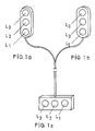
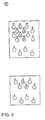
- the signal lamps L1, L2, and L3 in the form of traffic lights in a preferred embodiment at the front, outside the vehicle (FIG. 1a), and at the rear, outside the vehicle (FIG. 1b) and for control purposes for the driver inside the vehicle at the driver's seat (Fig. 1c), it serves in particular the traffic police to monitor and control the driving times performed by each of the drivers.
- the device is also used to avoid overloading and thus driver fatigue, which improves road safety on highways.
- the device works as follows: The device is switched on via the vehicle's ignition lock. Even if you switch off the ignition, the device remains switched on. When switched on, the green signal lamp L1 indicating that the first driver is driving lights up; After a driving time of four hours, the device switches on the second green signal lamp L2, which indicates that the vehicle is moving, for the second driver.
- the third red signal lamp L3 lights up briefly as a warning signal. At this point it is possible to switch over, after which the four-hour cycle starts again.
- the red, third signal lamp L3 After 16 hours of driving, the red, third signal lamp L3 only lights up as a warning signal to indicate compliance with the required rest and idle time for a further eight hours.
- a synchronization of the device with the tachograph is ensured by appropriate connections and by sealing the device.
- the device can be designed so that the driver is given the opportunity to switch the device back to the eight-hour standstill if the normal driving time of sixteen hours, for example because of a weekend driving ban, due to the end of the discharge times during the night, or at border crossings can be observed.
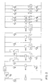
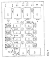
- a normally open contact of relay RE6 forms self-hold via the battery.
- Relay RE1 switches relay RE2 on.
- Relay RE2 with its four make contacts K2 / 1 to K2 / 4, switches on the four retarders Delay 1 to 4, which act as timers.
- Relay RE4 switches relay RE2 off again (by push button action).
- Relays RE3 to RE6 are energized. The first green LED D1 and the signal lamp L1 light up.
- relay RE3 drops out.
- the LED D1 and signal lamp L1 go out.
- the green light-emitting diode D2 which indicates that the second driver is driving freely, and the signal lamp L2 now light up.
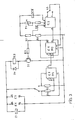
- the next activated delay time of delay 2 causes relay RE4 to drop out.
- the next activated delay time of delay 3 switches off relays RE3 and RE4.
- the signal lamp L3 and the light-emitting diode D3 now light up as a warning signal.
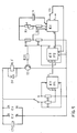
- the delay of the delay 4 switches off the entire circuit again after a set time.
- the relay is switched on by closing the make contacts K2 / 1, K2 / 2, K2 / 3 and K2 / 4 of relay RE2; the timer starts at the same time.
- the time between switching on and off can be set with the potentiometer P1 between one and twelve hours. If the value of C2 is increased, even longer times can be achieved. If C2 is doubled, the switch-off time is doubled.
- Switch S1 is switched on and off with the same circuit, such as delay 1.
Landscapes
- Physics & Mathematics (AREA)
- General Physics & Mathematics (AREA)
- Lighting Device Outwards From Vehicle And Optical Signal (AREA)
- Traffic Control Systems (AREA)
Applications Claiming Priority (4)
| Application Number | Priority Date | Filing Date | Title |
|---|---|---|---|
| DE8803878U | 1988-03-22 | ||
| DE8803878U DE8803878U1 (de) | 1988-03-22 | 1988-03-22 | Elektronisches Fahrzeitregelungs-Gerät für Kraftfahrzeuge |
| DE8812008U DE8812008U1 (de) | 1988-09-22 | 1988-09-22 | Elektronisches Fahrzeitregelungs-Gerät für Kraftfahrzeuge |
| DE8812008U | 1988-09-22 |
Publications (2)
| Publication Number | Publication Date |
|---|---|
| EP0334225A2 true EP0334225A2 (fr) | 1989-09-27 |
| EP0334225A3 EP0334225A3 (fr) | 1991-09-18 |
Family
ID=25952841
Family Applications (1)
| Application Number | Title | Priority Date | Filing Date |
|---|---|---|---|
| EP19890104781 Withdrawn EP0334225A3 (fr) | 1988-03-22 | 1989-03-17 | Dispositif électronique de contrôle de temps de conduite pour véhicules automobiles |
Country Status (1)
| Country | Link |
|---|---|
| EP (1) | EP0334225A3 (fr) |
Cited By (3)
| Publication number | Priority date | Publication date | Assignee | Title |
|---|---|---|---|---|
| FR2721460A1 (fr) * | 1994-06-15 | 1995-12-22 | Elsydel | Dispositif de communication, notamment pour le paiement à distance, comprenant un marqueur de transaction et système comprenant un tel dispositif. |
| EP1684251A3 (fr) * | 2001-02-20 | 2007-03-21 | Matsushita Electric Industrial Co., Ltd. | Direction de déplacement et dispositif d'avertissement |
| EP2605228A3 (fr) * | 2011-12-17 | 2013-11-06 | Tata Consultancy Services Limited | Détermination du temps de fatigue pour une activité |
Family Cites Families (4)
| Publication number | Priority date | Publication date | Assignee | Title |
|---|---|---|---|---|
| FR2298143A1 (fr) * | 1975-01-20 | 1976-08-13 | Martin Guy | Proce |
| JPS58167237A (ja) * | 1982-03-26 | 1983-10-03 | Koichi Nakamura | 自動車等の運転時間報知器 |
| FR2535088A1 (fr) * | 1982-10-21 | 1984-04-27 | Ricard Claude | Procede et dispositifs pour limiter l'activite quotidienne d'un chauffeur de taxi |
| US4602247A (en) * | 1983-02-18 | 1986-07-22 | Nissan Motor Company, Limited | Method and system for detecting driver fatigue including differentiation of effects of rest periods |
-
1989
- 1989-03-17 EP EP19890104781 patent/EP0334225A3/fr not_active Withdrawn
Cited By (3)
| Publication number | Priority date | Publication date | Assignee | Title |
|---|---|---|---|---|
| FR2721460A1 (fr) * | 1994-06-15 | 1995-12-22 | Elsydel | Dispositif de communication, notamment pour le paiement à distance, comprenant un marqueur de transaction et système comprenant un tel dispositif. |
| EP1684251A3 (fr) * | 2001-02-20 | 2007-03-21 | Matsushita Electric Industrial Co., Ltd. | Direction de déplacement et dispositif d'avertissement |
| EP2605228A3 (fr) * | 2011-12-17 | 2013-11-06 | Tata Consultancy Services Limited | Détermination du temps de fatigue pour une activité |
Also Published As
| Publication number | Publication date |
|---|---|
| EP0334225A3 (fr) | 1991-09-18 |
Similar Documents
| Publication | Publication Date | Title |
|---|---|---|
| DD154856A5 (de) | Verfahren und vorrichtung zur kontrolle der wachsamkeit von fahrzeugfuehrern,insbesondere kraftfahrern | |
| EP2048748B1 (fr) | Dispositif de raccordement sur une connexion de remorque d'un véhicule automobile | |
| DE2527877A1 (de) | Steuereinrichtung zum selbsttaetigen schalten von leuchten | |
| DE19953994B4 (de) | Verfahren und Schaltungsanordnung zur Betätigung einer Fahrzeugbeleuchtung | |
| DE2641006A1 (de) | Optische warneinrichtung fuer rettungsfahrzeuge u.dgl. | |
| AT337017B (de) | Vorrichtung zur anzeige und kontrolle von fahrgeschwindigkeiten in kraftfahrzeugen | |
| DE3042586A1 (de) | Anzeigeeinrichtung fuer kraftfahrzeuge | |
| DE3907648A1 (de) | Elektronisches fahrzeitregelungs-geraet fuer kraftfahrzeuge | |
| DE8812008U1 (de) | Elektronisches Fahrzeitregelungs-Gerät für Kraftfahrzeuge | |
| DE813114C (de) | Geschwindigkeitsanzeiger fuer Kraftfahrzeuge aller Art | |
| DE29610507U1 (de) | Vorrichtung zum Ein- und/oder Ausschalten von in Kraftfahrzeugen angeordneten Aggregaten | |
| DE4021146A1 (de) | Gefahrwarneinrichtung fuer taxenfahrzeuge | |
| DE4019507A1 (de) | Einrichtung zur datenerfassung in einem kraftfahrzeug | |
| DE3826121A1 (de) | Anzeige fuer geschwindigkeitsbegrenzungen | |
| DE2928927A1 (de) | Einrichtung fuer eine parkscheibe fuer kraft-fahrzeuge | |
| EP1008487A1 (fr) | Commutateur à commande par cellule photoélectrique avec dispositif d'intervention à durée limitée ou automatique pour la mise en circuit des lampes d'un véhicule à moteur | |
| DE2513296A1 (de) | Vorrichtung zur ueberwachung und steuerung des kurzzeitparkens | |
| DE225048C (fr) | ||
| DE3307476A1 (de) | Elektronischer blinkgeber fuer richtungs- und warnblinken mit definiertem warnblinkrythmus | |
| DE3837977A1 (de) | Verfahren und anordnung zur steuerung einer kontrollampe | |
| EP1102233A2 (fr) | Dispositif électronique avec un écran de visualisation | |
| DE552636C (de) | Vorrichtung zur UEberwachung der Geschwindigkeit eines Kraftfahrzeuges | |
| DE7512943U (de) | Transportable leuchteinrichtung fuer die anzeige von unfaellen o.dgl.bei kraftfahrzeugen | |
| DE19901810A1 (de) | Verfahren und Einrichtung zur Generierung einer Grenzgeschwindigkeitswarnung | |
| DE8803878U1 (de) | Elektronisches Fahrzeitregelungs-Gerät für Kraftfahrzeuge |
Legal Events
| Date | Code | Title | Description |
|---|---|---|---|
| PUAI | Public reference made under article 153(3) epc to a published international application that has entered the european phase |
Free format text: ORIGINAL CODE: 0009012 |
|
| AK | Designated contracting states |
Kind code of ref document: A2 Designated state(s): AT BE CH DE ES FR GB GR IT LI LU NL SE |
|
| PUAL | Search report despatched |
Free format text: ORIGINAL CODE: 0009013 |
|
| AK | Designated contracting states |
Kind code of ref document: A3 Designated state(s): AT BE CH DE ES FR GB GR IT LI LU NL SE |
|
| STAA | Information on the status of an ep patent application or granted ep patent |
Free format text: STATUS: THE APPLICATION IS DEEMED TO BE WITHDRAWN |
|
| 18D | Application deemed to be withdrawn |
Effective date: 19920319 |