EP0334255A1 - Druckluftsteuersystem zum Überwachen des Blutdrucks eines Neugeborenen - Google Patents
Druckluftsteuersystem zum Überwachen des Blutdrucks eines Neugeborenen Download PDFInfo
- Publication number
- EP0334255A1 EP0334255A1 EP89104929A EP89104929A EP0334255A1 EP 0334255 A1 EP0334255 A1 EP 0334255A1 EP 89104929 A EP89104929 A EP 89104929A EP 89104929 A EP89104929 A EP 89104929A EP 0334255 A1 EP0334255 A1 EP 0334255A1
- Authority
- EP
- European Patent Office
- Prior art keywords
- cuff
- blood pressure
- air
- air pump
- valve
- Prior art date
- Legal status (The legal status is an assumption and is not a legal conclusion. Google has not performed a legal analysis and makes no representation as to the accuracy of the status listed.)
- Withdrawn
Links
- 230000036772 blood pressure Effects 0.000 title claims abstract description 98
- 238000012544 monitoring process Methods 0.000 title description 5
- 230000017531 blood circulation Effects 0.000 claims abstract description 19
- 230000002441 reversible effect Effects 0.000 claims description 11
- 210000001367 artery Anatomy 0.000 claims description 5
- 238000013022 venting Methods 0.000 abstract description 7
- 238000005259 measurement Methods 0.000 description 9
- 238000009530 blood pressure measurement Methods 0.000 description 8
- 239000008280 blood Substances 0.000 description 5
- 210000004369 blood Anatomy 0.000 description 5
- 230000000694 effects Effects 0.000 description 5
- 230000003205 diastolic effect Effects 0.000 description 3
- 230000002035 prolonged effect Effects 0.000 description 3
- 230000009467 reduction Effects 0.000 description 3
- 238000006722 reduction reaction Methods 0.000 description 3
- 208000036366 Sensation of pressure Diseases 0.000 description 2
- 230000002411 adverse Effects 0.000 description 2
- 238000013459 approach Methods 0.000 description 2
- 230000000903 blocking effect Effects 0.000 description 2
- 238000001514 detection method Methods 0.000 description 2
- 230000035487 diastolic blood pressure Effects 0.000 description 2
- 230000035488 systolic blood pressure Effects 0.000 description 2
- 206010013082 Discomfort Diseases 0.000 description 1
- 241001661807 Systole Species 0.000 description 1
- 230000001154 acute effect Effects 0.000 description 1
- 230000000740 bleeding effect Effects 0.000 description 1
- 230000000593 degrading effect Effects 0.000 description 1
- 230000005669 field effect Effects 0.000 description 1
- 238000012986 modification Methods 0.000 description 1
- 230000004048 modification Effects 0.000 description 1
- 230000000474 nursing effect Effects 0.000 description 1
- 230000000737 periodic effect Effects 0.000 description 1
- 238000005086 pumping Methods 0.000 description 1
Images

Classifications
-
- A—HUMAN NECESSITIES
- A61—MEDICAL OR VETERINARY SCIENCE; HYGIENE
- A61B—DIAGNOSIS; SURGERY; IDENTIFICATION
- A61B5/00—Measuring for diagnostic purposes; Identification of persons
- A61B5/02—Detecting, measuring or recording for evaluating the cardiovascular system, e.g. pulse, heart rate, blood pressure or blood flow
- A61B5/021—Measuring pressure in heart or blood vessels
- A61B5/022—Measuring pressure in heart or blood vessels by applying pressure to close blood vessels, e.g. against the skin; Ophthalmodynamometers
Definitions
- This invention relates to blood pressure monitoring systems, and more particularly, to a system for pumping air into a blood pressure monitoring cuff, preventing inadvertent leakage of air from the cuff during a blood pressure measurement, and providing two independent leakage paths from the cuff after the measurement.
- Blood pressure monitors are commonly used to take blood pressure measurements without nursing assistance.
- Typical blood pressure monitors include an air pump that supplies pressurized air to a conventional blood pressure cuff and a pressure transducer that measures the pressure of air in the cuff.
- the air pump is energized for a predetermined period to inflate the cuff.
- an electronic or acoustic audio pickup is used to determine if blood is flowing in an artery beneath the cuff during both the systolic and diastolic portions of the heart cycle.
- the air pressure in the cuff is measured, at all times, by the pressure transducer. Blood flow is normally not detected as soon as the cuff is fully inflated since the cuff pressure is then at its maximum value. If no blood flow is detected, the air is rapidly bled from the cuff until the pressure has been reduced an incremental value.
- the cuff pressure is once again held at that value while an attempt is made to detect blood flow in the artery during the systolic and diastolic portions of the heart cycle. This cycle of incremental pressure reduction, pressure hold, and blood flow detection is repeated until blood flow is detected during both the systolic and diastolic portions of the heart cycle.
- the cuff pressure at which blood starts to flow during systole is recorded as the systolic blood pressure, while the cuff pressure at which blood starts to flow during diastole is recorded as the diastolic blood pressure.
- a manual blood pressure monitor In a manual blood pressure monitor, the operation of the air pump and valve may be manually controlled.
- most of the above-described blood pressure monitors are automatic and they take blood pressure measurements on a periodic basis.
- These automatic blood pressure monitors utilize conventional electronic timing and control circuits to periodically trigger the start of a measurement and to then control the energization of the air pump and valve, record the resulting air pressures in the cuff, and detect the presence of blood flow in an artery beneath the cuff.
- the conventional air pumps used in manual and automatic blood pressure monitors have a tendency to leak air during blood pressure measurements.
- This inadvertent leakage can adversely affect the accuracy of blood pressure measurements because the air pressure in the cuff will be changing while a measurement is being taken.
- the rate of leakage is not uniform even for the same model of pump, so the leakage cannot be compensated for by the monitor.
- conventional air pumps are adequate for use in blood pressure monitors for adults because the blood pressure cuffs used by adults have relatively large air volumes. As a result, the leakage has a relatively small effect on the pressure in the cuff.
- blood pressure cuffs used for neonatals have air volumes that are substantially smaller than the air volumes of adult blood pressure cuffs.
- the inadvertent leakage through air pumps can have a drastic effect on the pressure in neonatal blood pressure cuffs. This leakage can, therefore, adversely affect the accuracy of blood pressure monitors used for neonatals.
- Another problem with conventional blood pressure monitors stems from their inability to bleed air from the blood pressure cuff each time the pressure is to be incrementally reduced.
- an air valve is actuated to bleed the air from the cuff to reduce the cuff pressure by an incremental value until blood flow is detected during both systole and diastole. If the valve fails, the intended path of leakage does not exist and the blood pressure cuff remains inflated for an exceptionally long period. Prolonged inflation of blood pressure cuffs is undesirable because it can cause discomfort to the patient. This problem is particularly acute where attempts have been made to prevent the reverse flow of air through the air pump, thereby further prolonging the inflation of the cuff.
- a pneumatic control system for blood pressure monitors having an inflatable blood pressure cuff.
- the control system includes an air pump generating pressurized air in its energized condition and allowing air to leak through the pump in the reverse direction when the pump is de-energized.
- a first valve is connected between the air pump and blood pressure cuff. The first valve has a first position allowing airflow between the air pump and blood pressure cuff and a second position isolating the air pump from the blood pressure cuff.
- a second valve is connected between the blood pressure cuff and the atmosphere. The second valve has a first position allowing airflow between the blood pressure cuff and one air vent and a second position isolating the blood pressure cuff from the atmosphere.
- a control circuit selects between inflate, hold, and deflate conditions.
- the control circuit In the inflate condition, the control circuit energizes the air pump, switches the first valve to its first position, and switches the second valve to its second position.
- the control circuit In the hold condition, the control circuit de-energizes the air pump and switches the first and second valves to their second positions.
- the control circuit In the deflate condition, the control circuit de-energizes the air pump and switches the first and second valves to their first positions.
- the air pump is isolated from the air cuff in the hold condi tion and the air cuff is vented through both valves in the deflate condition.
- the first and second valves are preferably in their first positions when they are de-ener gized and switch to their second positions when they are energized so that both valves vent the blood pressure cuff when they are de-energized. As a result, the cuff is vented in the event of a power loss in the control system.
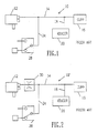
- a conventional blood pressure monitor 10 includes a conventional air pump 12 connected through a pneumatic line 14 to a conventional blood pressure cuff 16.
- Another pneumatic line 18 extends from line 14 to a conventional pressure transducer 20.
- the transducer thus measures the pressure of the air in the blood pressure cuff 16 after it is inflated by the air pump 12.
- a third pneumatic line 24 extends from line 14 to a two-way valve 28. In its first position, the valve 28 vents line 24 to atmosphere. In its second position, the valve 24 effectively prevents air from leaking from line 24.
- Conventional, well-known electronic circuits control the air pump 12 and valve 28 and interface with the pressure transducer 20. These circuits need not be understood to understand the subject matter of the invention, and their description has, therefore, been omitted in the interests of brevity.
- the air pump 12 is energized to inflate the cuff until the pressure transducer 20 registers a predetermined pressure.
- An attempt is then made to detect blood flow in an artery beneath the cuff during both systole and diastole using an electronic or acoustic audio pickup (not shown).
- the air pressure in the cuff is measured, at all times, by the pressure transducer 20.
- the valve 28 is actuated from its second position to its first position, thereby rapidly bleeding air from the cuff 16 until the pressure transducer 20 measures that the cuff pressure has been reduced an incremental value.
- the valve 28 is then shifted back to its second position to once again hold the air pressure in the cuff 16 constant while an attempt is made to detect blood flow.
- This cycle of incremental pressure reduction, pressure hold, and blood flow detection is repeated until blood flow is detected during both systole and diastole.
- the cuff pressure at which blood starts to flow during systole is recorded as the systolic blood pressure, while the cuff pressure at which blood starts to flow during diastole is recorded at the diastolic blood pressure.
- the prior art blood pressure monitor illustrated in Figure 1 exemplifies both of the problems solved by the inventive pneumatic control system.
- the air pressure in the cuff 16 should be constant in order to obtain an accurate measurement.
- the valve 28 is in its second position, air inadvertently bleeds from the cuff 16 through the air pump 12.
- FIG. 2 One approach to solving the problem of inadvertent air leakage from the cuff 16 is illustrated in Figure 2.
- Most of the components used in the monitor 10′ of Figure 2 are common to the components used in the monitor 10 of Figure 1, and they operate in the same manner in both monitors. Accordingly, these common components have been given the same reference numerals in Figure 2, and in the interest of brevity, an explanation of their operation will not be repeated.
- the monitor of Figure 2 adds a conventional one-way check valve 30 in series with the air pump 12 in an attempt to prevent the reverse flow of air through the air pump 12.
- conventional one-way check valves are not effective in preventing reverse flow at the relatively low pressures found in blood pressure cuffs.
- placing the one-way check valve 30 in series with the air pump 12 has no effect on the inability of the monitor 10′ to bleed air from the cuff 16 when desired in the event of a failure of the valve 28.
- a blood pressure monitor 40 that solves both of the problems inherent in conventional monitors is illustrated in Figures 3-6.
- the monitor 40 utilizes some of the same components operating in the same manner as in the monitors 10, 10′ of Figures 1 and 2, respectively. Accordingly, these components have been given the same reference numerals in all cases. These common components include the air pump 12, blood pressure cuff 16, pressure transducer 20, and two-way valve 28.
- the inventive blood pressure monitor 40 further includes a second two-way valve 42 connecting the air pump 12 to the blood pressure cuff 16 in its first position and blocking all airflow to the air pump 12 in its second position.
- the blood pressure monitor 40 is shown in Figure 3 in the "inflate" portion of its operating cycle.
- the air pump 12 is energized, the valve 42 is unenergized to connect the air pump 12 to the blood pressure cuff 16, and the valve 28 is energized to prevent air from being bled from the cuff 16.
- the air pump 12 continues to inflate the cuff 16, the air pressure in the cuff is measured by the pressure transducer.
- the monitor 40 When the air pressure reaches a predetermined value, the monitor 40 is switched to the "hold" portion of its operating cycle, as shown in Figure 4.
- the air pump 12 In the "hold” condition, the air pump 12 is de-energized, the valve 42 is energized to its second position to isolate the air pump 12 from the remainder of the system, and the valve 28 remains energized in its second position to prevent air from being bled from the cuff 16.
- the air pressure in the cuff 16 therefore remains constant as an attempt is made to detect blood flow since there is no leakage path from the cuff 16.
- the monitor shifts back to the "hold” condition by energizing the valve 28 to its second position, in which airflow through the valve 28 is prevented.
- the monitor 40 continues to shift back and forth between the “hold and “deflate” conditions and to detect any blood flow during each "hold” condition until blood flow has been detected during both systole and diastole.
- the monitor 40 then shifts to the "deflate” condition to bleed all of the air from the cuff 16 until the next measurement is to be taken.
- the monitor not only prevents any leakage from the cuff 16 during the measurements, but it also ensures that the cuff 16 is vented after the measurements have been taken.
- Either of the valves 42 or 28 is capable of venting the cuff 16.
- the valve 28 vents the cuff 16 relatively quickly, but the valve 42 will also vent the cuff 16 through the air pump 12 with sufficient rapidity to prevent patient discomfort.
- both of the valves 42, 28 are shifted to their respective venting position when they are de-energized. As a result, the cuff 16 is assured of being vented if either of the valves 42 or 28 is jammed in its energized position or if all power is lost to both valves 42, 28.
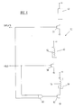
- control circuit 50 is illustrated in Figure 6.
- the circuit is operated by binary "inflate” and “hold” signals which may have a logic level of either “1” or “0.” The absence of a high “inflate” or “hold” signal automatically signals the “deflate” condition.
- the "inflate” and “hold” signals may be generated either manually by respective switches or by conventional automatic timing and control circuits.
- the pump 12, and actuating coils 52, 54 in the valves 42, 28, respectively, are each connected between a supply voltage and a respective field effect transistor (FET) switch 56, 58, 60.
- FET field effect transistor
- the drain of each FET 56, 58, 60 is connected to ground so that current flows through the FET when a logic "1" voltage level is applied to its respective gate.
- the "1" logic level is also applied to the FET 60 through an OR gate 62 to pull current through the actuating coil 54 for the valve 28, thereby shifting the valve 28 to its second position, as illustrated in Figure 3.
- the FET 58 remains turned off, so the valve 42 remains de-energized.
- the "hold” input rises to a logic “1,” thereby turning on FETS 58 and 60.
- Current then flows through the actuating coils 52, 54 of the valves 42, 28, respectively, thereby energizing the valves 42, 28, as illustrated in Figure 5.
- valves 28, 42 are described as being two-way valves, it will be understood that one-way valves can be used as long as the one-way valves isolate two pneumatic ports from each other when the valve is energized and connect the ports to each other when the valve is de-energized. Also, if leakage through the air pump 12 is not sufficient to vent the cuff 12 through the valve 42 and if the valve 28 sticks in its second position, a leakage path 46 may be installed at the air pump 12. The leakage path has no effect on the monitor 40 in the "hold" condition since the valve 42 isolates the air pump 12 from the remainder of the system.
- the leakage path causes a slight but inconsequential decrease in the effective capacity of the pump 12. Finally, in the "deflate” condition, the leakage path causes faster venting of the cuff 12. However, since the rate of cuff deflation is irrelevant, the leakage path has no effect on the monitor in the "deflate” condition.
- the inventive blood pressure monitor 40 avoids both of the problems inherent in conventional monitors, particularly when those monitors are used for neonatal applications.
- the monitor 40 thus not only prevents the inadvertent flow of air from the cuff 12, but it also ensures that air will be vented from the cuff when desired.
Landscapes
- Health & Medical Sciences (AREA)
- Life Sciences & Earth Sciences (AREA)
- Vascular Medicine (AREA)
- Cardiology (AREA)
- Biomedical Technology (AREA)
- Heart & Thoracic Surgery (AREA)
- Physiology (AREA)
- Biophysics (AREA)
- Pathology (AREA)
- Engineering & Computer Science (AREA)
- Ophthalmology & Optometry (AREA)
- Physics & Mathematics (AREA)
- Medical Informatics (AREA)
- Molecular Biology (AREA)
- Surgery (AREA)
- Animal Behavior & Ethology (AREA)
- General Health & Medical Sciences (AREA)
- Public Health (AREA)
- Veterinary Medicine (AREA)
- Measuring Pulse, Heart Rate, Blood Pressure Or Blood Flow (AREA)
Applications Claiming Priority (2)
| Application Number | Priority Date | Filing Date | Title |
|---|---|---|---|
| US172287 | 1988-03-23 | ||
| US07/172,287 US4924873A (en) | 1988-03-23 | 1988-03-23 | Pneumatic control system for neonatal blood pressure monitoring |
Publications (1)
| Publication Number | Publication Date |
|---|---|
| EP0334255A1 true EP0334255A1 (de) | 1989-09-27 |
Family
ID=22627067
Family Applications (1)
| Application Number | Title | Priority Date | Filing Date |
|---|---|---|---|
| EP89104929A Withdrawn EP0334255A1 (de) | 1988-03-23 | 1989-03-20 | Druckluftsteuersystem zum Überwachen des Blutdrucks eines Neugeborenen |
Country Status (4)
| Country | Link |
|---|---|
| US (1) | US4924873A (de) |
| EP (1) | EP0334255A1 (de) |
| JP (1) | JPH0221843A (de) |
| CA (1) | CA1299968C (de) |
Families Citing this family (12)
| Publication number | Priority date | Publication date | Assignee | Title |
|---|---|---|---|---|
| US5542428A (en) * | 1995-03-23 | 1996-08-06 | Spacelabs Medical, Inc. | Method and apparatus for removing artifact encountered during automatic blood pressure measurements |
| US6171254B1 (en) | 1999-02-26 | 2001-01-09 | Medical Research Laboratories, Inc. | Control for automatic blood pressure monitor |
| US7226419B2 (en) * | 2005-06-22 | 2007-06-05 | Welch Allyn, Inc. | Mode detection and safety monitoring in blood pressure measurement |
| US20090326394A1 (en) * | 2008-06-25 | 2009-12-31 | General Electric Company | Blood pressure cuff apparatus and system |
| JP5239806B2 (ja) * | 2008-12-09 | 2013-07-17 | オムロンヘルスケア株式会社 | 電子血圧計 |
| TWI604821B (zh) * | 2016-11-11 | 2017-11-11 | Microlife Corp | 具有壓電幫浦的血壓測量裝置及具有壓電幫浦的血壓測量裝置的控制方法 |
| EP3456252A1 (de) | 2017-09-14 | 2019-03-20 | Koninklijke Philips N.V. | Aufpumpvorrichtung für einen aufpumpbasierten nichtinvasiven blutdruckmonitor und verfahren zum betrieb davon |
| CN109998510A (zh) * | 2019-04-08 | 2019-07-12 | 深圳市贝斯曼精密仪器有限公司 | 一种血压检测装置及血压检测方法 |
| CN110200613B (zh) * | 2019-04-08 | 2024-02-20 | 深圳市贝斯曼精密仪器有限公司 | 一种血流血压检测装置 |
| IT201900010248A1 (it) * | 2019-06-27 | 2020-12-27 | Tre Esse Progettazione Biomedica S R L | Dispositivo per la rilevazione della pressione venosa |
| KR20210117693A (ko) * | 2020-03-20 | 2021-09-29 | (주)참케어 | 혈압측정 시스템 및 이를 이용한 혈압 측정 방법 |
| JP7622370B2 (ja) * | 2020-07-27 | 2025-01-28 | オムロンヘルスケア株式会社 | 血圧計、血圧測定方法、およびプログラム |
Citations (5)
| Publication number | Priority date | Publication date | Assignee | Title |
|---|---|---|---|---|
| US3157177A (en) * | 1963-02-07 | 1964-11-17 | Dynamics Corp America | Systolic diastolic blood pressure follower |
| CH517480A (de) * | 1970-03-09 | 1972-01-15 | Oripid Ag | Blutdruckmessgerät |
| GB2165052A (en) * | 1984-09-27 | 1986-04-03 | Copal Takeda Medical Lab Inc | Automatically measuring blood pressure |
| US4671290A (en) * | 1985-01-15 | 1987-06-09 | Richards Medical Company | Automatic tourniquet |
| EP0208520B1 (de) * | 1985-07-05 | 1992-04-15 | Critikon, Inc. | Oszillometrische Blutdrucküberwachung während Druckablass mittels veränderlicher Druckintervalle |
Family Cites Families (8)
| Publication number | Priority date | Publication date | Assignee | Title |
|---|---|---|---|---|
| US2811964A (en) * | 1956-03-27 | 1957-11-05 | Radio Patents Company | Sphygmomanometric control system |
| US3978848A (en) * | 1975-01-09 | 1976-09-07 | Filac Corporation | Monitoring apparatus and method for blood pressure and heart rate |
| US4116230A (en) * | 1976-09-10 | 1978-09-26 | Gorelick Donald E | Blood pressure cuff automatic deflation device |
| DE2657519C2 (de) * | 1976-12-18 | 1984-11-29 | Schwarzhaupt Medizintechnik GmbH, 5000 Köln | Blutdruckmanschette |
| DE2948067A1 (de) * | 1979-11-29 | 1981-06-04 | Robert Bosch Gmbh, 7000 Stuttgart | Blutdruckmesseinrichtung |
| US4378807A (en) * | 1980-12-03 | 1983-04-05 | Clinical Data, Inc. | Blood pressure measurement apparatus |
| US4627440A (en) * | 1985-07-05 | 1986-12-09 | Critikon, Inc. | Sphygmomanometric cuff pressurizing system |
| US4774960A (en) * | 1986-10-30 | 1988-10-04 | Datascope Corporation | Method and apparatus for measuring blood pressure |
-
1988
- 1988-03-23 US US07/172,287 patent/US4924873A/en not_active Expired - Fee Related
-
1989
- 1989-03-10 CA CA000593415A patent/CA1299968C/en not_active Expired - Fee Related
- 1989-03-20 EP EP89104929A patent/EP0334255A1/de not_active Withdrawn
- 1989-03-23 JP JP1071593A patent/JPH0221843A/ja active Pending
Patent Citations (5)
| Publication number | Priority date | Publication date | Assignee | Title |
|---|---|---|---|---|
| US3157177A (en) * | 1963-02-07 | 1964-11-17 | Dynamics Corp America | Systolic diastolic blood pressure follower |
| CH517480A (de) * | 1970-03-09 | 1972-01-15 | Oripid Ag | Blutdruckmessgerät |
| GB2165052A (en) * | 1984-09-27 | 1986-04-03 | Copal Takeda Medical Lab Inc | Automatically measuring blood pressure |
| US4671290A (en) * | 1985-01-15 | 1987-06-09 | Richards Medical Company | Automatic tourniquet |
| EP0208520B1 (de) * | 1985-07-05 | 1992-04-15 | Critikon, Inc. | Oszillometrische Blutdrucküberwachung während Druckablass mittels veränderlicher Druckintervalle |
Also Published As
| Publication number | Publication date |
|---|---|
| CA1299968C (en) | 1992-05-05 |
| US4924873A (en) | 1990-05-15 |
| JPH0221843A (ja) | 1990-01-24 |
Similar Documents
| Publication | Publication Date | Title |
|---|---|---|
| US4924873A (en) | Pneumatic control system for neonatal blood pressure monitoring | |
| EP0207805B1 (de) | Vorrichtung zur Druckerzeugung für eine Blutdruck-Manschette | |
| US6450966B1 (en) | Method for non-invasive blood pressure cuff identification using deflation pressure measurements | |
| JP2965996B2 (ja) | 血圧モニター | |
| US6475228B1 (en) | System and method of controlling pressure in a surgical tourniquet | |
| EP1876973B1 (de) | Chirurgisches staugerät zur messung des okklusionsdrucks in gliedmassen | |
| US5069219A (en) | Self snugging universal blood pressure cuff | |
| EP2314268B1 (de) | Kompressionsbehandlungssystem | |
| US5240008A (en) | Inflation control apparatus for an automatic blood pressure gauge | |
| US3157177A (en) | Systolic diastolic blood pressure follower | |
| AU2021269353A1 (en) | Pressure sensitive arrangement and method for use thereof | |
| US6589183B2 (en) | Arterial-hardness evaluating apparatus | |
| US5464019A (en) | Airflow control manifold for automatic blood pressure monitoring device | |
| US7862514B2 (en) | Blood pressure measurement | |
| HK44093A (en) | Oscillometric blood pressure monitor employing non uniform pressure decrementing steps | |
| US5172697A (en) | Cuff inflation system | |
| US3137292A (en) | Blood pressure apparatus | |
| CN211749576U (zh) | 测压控制系统及血压测量设备 | |
| US11723670B2 (en) | Automatic tourniquet apparatus having patient hazard shield | |
| CN222426003U (zh) | 血压测量控制装置和电路 | |
| WO2009130635A1 (en) | Adaptive blood pressure system and cuff hose | |
| CN118697310A (zh) | 血压测量控制装置和方法 | |
| JP2018015506A (ja) | 半自動式血圧計システム |
Legal Events
| Date | Code | Title | Description |
|---|---|---|---|
| PUAI | Public reference made under article 153(3) epc to a published international application that has entered the european phase |
Free format text: ORIGINAL CODE: 0009012 |
|
| AK | Designated contracting states |
Kind code of ref document: A1 Designated state(s): CH DE FR GB IT LI |
|
| 17P | Request for examination filed |
Effective date: 19900312 |
|
| 17Q | First examination report despatched |
Effective date: 19930119 |
|
| STAA | Information on the status of an ep patent application or granted ep patent |
Free format text: STATUS: THE APPLICATION IS DEEMED TO BE WITHDRAWN |
|
| 18D | Application deemed to be withdrawn |
Effective date: 19940413 |