EP0334294A2 - Procédé de fabrication de coquilles monopièces courbées en arc - Google Patents
Procédé de fabrication de coquilles monopièces courbées en arc Download PDFInfo
- Publication number
- EP0334294A2 EP0334294A2 EP89105046A EP89105046A EP0334294A2 EP 0334294 A2 EP0334294 A2 EP 0334294A2 EP 89105046 A EP89105046 A EP 89105046A EP 89105046 A EP89105046 A EP 89105046A EP 0334294 A2 EP0334294 A2 EP 0334294A2
- Authority
- EP
- European Patent Office
- Prior art keywords
- mandrel
- tubular body
- roller
- curvature
- sliding guide
- Prior art date
- Legal status (The legal status is an assumption and is not a legal conclusion. Google has not performed a legal analysis and makes no representation as to the accuracy of the status listed.)
- Withdrawn
Links
Images
Classifications
-
- B—PERFORMING OPERATIONS; TRANSPORTING
- B21—MECHANICAL METAL-WORKING WITHOUT ESSENTIALLY REMOVING MATERIAL; PUNCHING METAL
- B21D—WORKING OR PROCESSING OF SHEET METAL OR METAL TUBES, RODS OR PROFILES WITHOUT ESSENTIALLY REMOVING MATERIAL; PUNCHING METAL
- B21D9/00—Bending tubes using mandrels or the like
- B21D9/12—Bending tubes using mandrels or the like by pushing over a curved mandrel; by pushing through a curved die
Definitions
- the invention relates to a process for the production of arcuately curved, one-piece molds, in particular made of copper, for continuous casting, a tubular body having a substantially rectangular cross section being bent by introducing a curved mandrel which defines the arc shape of the mold and cold forming on the mandrel .
- Such a method is carried out according to DE-OS 18 09 633 in such a way that the curved mandrel is first pressed into the tubular body, and that the cold forming is then carried out on the mandrel.
- the tubular body thus initially assumes an approximate shape of the mandrel which, in the course of the subsequent cold forming, continues to transfer its shape and dimension to the tubular body.
- the object of the invention is to improve the dimensional stability of the mold to be produced from the tubular body.
- the invention is based on a tubular body with a rectangular cross section.
- the mold is already finished according to the invention when the entire length of the tubular body is pushed onto the mandrel or when the latter is pushed into it.
- the mandrel to be inserted transfers its dimensions and shape in its entirety from the outset to the tubular body, which, particularly on the inner curvature side, cannot stand out from the mandrel because of the compression that would otherwise occur there.
- the forming conditions of the tubular body are therefore constant over its entire length, which leads to a considerably improved dimensional stability of the mold over its entire length.
- An axial length that is at least equal to the width of the adjacent side of a tubular body is required for the roll.
- the diameter of the roller should be as large as possible to ensure even pressure on the inner curve side. In the case of a plurality of rollers, as are expedient in the case of a greater curvature, the roller diameter, however, needs to be optimized so that there is sufficient space on the inner curve side for the intended number of rollers.
- the tubular body is pushed onto the fixed mandrel, a thrust member acting on the free end of the tubular body and accordingly being able to perform a linear movement.
- the mandrel, the sliding guide and the position of the rollers can be arranged in a fixed position.
- the tubular body As soon as the tubular body has assumed the arcuate curvature provided, it can continue to be pushed onto the mandrel without deformation. It is therefore sufficient if the tubular body is subjected to the sliding guide approximately to the middle. In the case of shorter tubular bodies and less curvature, a roller in the middle pressing on the inner curvature side is sufficient, while in the case of longer tubular bodies and greater curvature one or more rollers advantageously also take over the pressure.
- a further improvement in dimensional accuracy is achieved by supporting the side surfaces of the tubular body in the vicinity of the inner curvature side. This purpose is served by rollers of smaller diameter, which act on the side surfaces in the same area as the roller lying on the inner curvature side. In this way, the tendency of the tubular body to widen when bending on the inner curve side is countered from the outset.
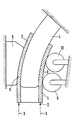
- the drawing shows the tubular body 1, which is under the action of a thrust device acting on its free end 2, by which it is acted upon in the direction of the arrows 3.
- the arcuate curved mandrel 4 is arranged in a stationary manner.
- the force 3 acting on the outside of the curvature of the tubular body 1 is intercepted in this way.
- rollers 9 and 10 which bear against the inner curvature side 8 and which are also mounted in a stationary manner.
- the rollers press the inside of the curvature against the mandrel 4, so that dimensional deviations are excluded.
Landscapes
- Engineering & Computer Science (AREA)
- Mechanical Engineering (AREA)
- Bending Of Plates, Rods, And Pipes (AREA)
- Continuous Casting (AREA)
Applications Claiming Priority (2)
| Application Number | Priority Date | Filing Date | Title |
|---|---|---|---|
| DE19883809936 DE3809936C2 (de) | 1988-03-24 | 1988-03-24 | Verfahren zur Herstellung von bogenförmig gekrümmten, einteiligen Kokillen |
| DE3809936 | 1988-03-24 |
Publications (2)
| Publication Number | Publication Date |
|---|---|
| EP0334294A2 true EP0334294A2 (fr) | 1989-09-27 |
| EP0334294A3 EP0334294A3 (fr) | 1990-10-31 |
Family
ID=6350579
Family Applications (1)
| Application Number | Title | Priority Date | Filing Date |
|---|---|---|---|
| EP19890105046 Withdrawn EP0334294A3 (fr) | 1988-03-24 | 1989-03-21 | Procédé de fabrication de coquilles monopièces courbées en arc |
Country Status (2)
| Country | Link |
|---|---|
| EP (1) | EP0334294A3 (fr) |
| DE (1) | DE3809936C2 (fr) |
Cited By (2)
| Publication number | Priority date | Publication date | Assignee | Title |
|---|---|---|---|---|
| FR2705595A1 (fr) * | 1993-05-25 | 1994-12-02 | Hutchinson | Dispositif, procédé de galbage de coulisses, et coulisse obtenue par ledit procédé. |
| CN105127259A (zh) * | 2015-09-29 | 2015-12-09 | 西安优耐特容器制造有限公司 | 一种薄壁弯头的推制成型方法 |
Families Citing this family (1)
| Publication number | Priority date | Publication date | Assignee | Title |
|---|---|---|---|---|
| DE19750858B4 (de) * | 1997-11-17 | 2008-02-28 | Egon Evertz Kg | Verfahren zum Herstellen einer Stranggießkokille |
Family Cites Families (5)
| Publication number | Priority date | Publication date | Assignee | Title |
|---|---|---|---|---|
| DE445075C (de) * | 1926-02-09 | 1927-06-03 | Rohrbogenwerk G M B H | Vorrichtung zur Herstellung von Rohrbogen, Rohrschlangen usw |
| DE570251C (de) * | 1931-05-10 | 1933-02-13 | Rohrbogenwerk G M B H | Herstellung von Rohrbogen o. dgl. mittels Biegeform, Biegerollen, Walzenbiegewerke o. dgl. |
| US2221417A (en) * | 1938-11-18 | 1940-11-12 | Taylor James Hall | Means for finishing bends |
| DE1809653A1 (de) * | 1968-11-19 | 1970-06-04 | Jaeger Kg Frank | Lueftungsvorrichtung zum Einbau in einen Lueftungsspalt,insbesondere ueber einem Fenster oder einer Fensterscheibe |
| DE2555903A1 (de) * | 1975-12-12 | 1977-06-23 | Moeller Sidro Fab | Vorrichtung zum biegen von rohren zu rohrboegen |
-
1988
- 1988-03-24 DE DE19883809936 patent/DE3809936C2/de not_active Expired - Fee Related
-
1989
- 1989-03-21 EP EP19890105046 patent/EP0334294A3/fr not_active Withdrawn
Cited By (2)
| Publication number | Priority date | Publication date | Assignee | Title |
|---|---|---|---|---|
| FR2705595A1 (fr) * | 1993-05-25 | 1994-12-02 | Hutchinson | Dispositif, procédé de galbage de coulisses, et coulisse obtenue par ledit procédé. |
| CN105127259A (zh) * | 2015-09-29 | 2015-12-09 | 西安优耐特容器制造有限公司 | 一种薄壁弯头的推制成型方法 |
Also Published As
| Publication number | Publication date |
|---|---|
| DE3809936A1 (de) | 1989-10-05 |
| EP0334294A3 (fr) | 1990-10-31 |
| DE3809936C2 (de) | 2002-11-21 |
Similar Documents
| Publication | Publication Date | Title |
|---|---|---|
| DE69312807T2 (de) | Verfahren und Vorrichtung zum Herstellen einer rohrförmigen Zahnstange | |
| EP0014461B1 (fr) | Dispositif pour cintrer des tubes métalliques | |
| DE10196332B4 (de) | Fertigungsvorrichtung für ein gekrümmtes Metallrohr mit einem beliebig geformten Querschnitt und Verfahren zur Herstellung eines gekrümmten Metallrohres und einer gekrümmten Metallstange | |
| DE2303172B2 (de) | Dorn einer Vorrichtung zum gleichzeitigen Erzeugen schraubenförmiger Innen- und Aussenrfppen an Rohren | |
| DE1946178C3 (de) | Verfahren zur Herstellung von Innenprofilen in rohrförmigen Werkstücken | |
| DE1900741C3 (de) | Vorrichtung zur Formgebung konischer Metallrohre | |
| DE3224625A1 (de) | Biegeeinheit fuer rohre und draehte aus metall und verfahren fuer die inbetriebsetzung der einheit | |
| DE69524188T2 (de) | Verfahren zur Herstellung des Laufrings eines Lagers | |
| EP0334294A2 (fr) | Procédé de fabrication de coquilles monopièces courbées en arc | |
| DE1427915B2 (de) | Walzwerk zum herstellen nahtloser rohre | |
| DE2154226C2 (de) | Anordnung zur Herstellung von kreisbogenförmig gekrümmten Kokillen für Stranggußmaschinen | |
| DE2130736C3 (de) | Aus einer Aluminiumlegierung geschmiedeter Kolben | |
| DE4226402C2 (de) | Verfahren zur Herstellung von langen dickwandigen Rohren durch Biegen aus einer Metallplatte und Vorrichtung zur Ausführung des Verfahrens | |
| DE3150426C2 (fr) | ||
| DE2832763A1 (de) | Stuetzspirale fuer einen schlauch und schlauchanordnung mit stuetzspirale | |
| DE1807814A1 (de) | Automatische Maschine zur Vorbereitung der Enden von Metallrohren fuer den Ziehvorgang | |
| CH685432A5 (de) | Kokille zum Stranggiessen von Metall, insbesondere von Stahl in Knüppel- und Vorblockquerschnitte. | |
| DE2006109B2 (de) | Metallrohrrahmen für Bett-, Tischgestelle od.dgL, insbesondere für Rahmen von Kraftfahrzeug-Sitzen | |
| DE2804644C2 (de) | Verfahren bzw. Einrichtung zur Herstellung eines Metall-Rippenkörper-Wärmetauschers | |
| DE1261102B (de) | Verfahren und Vorrichtung zum Herstellen von Rohrbogen mit sich vom einen zum anderen Ende gleichmaessig verjuengendem Querschnitt | |
| DE2458240C2 (fr) | ||
| DE69401752T2 (de) | Radial-extrusionsverfahren kombiniert mit innerem glattziehen des rohres | |
| DE19610642A1 (de) | Verfahren und Vorrichtung zum Kaltziehen von nahtlosen Rohren | |
| DE2831833C2 (de) | Mehrteiliger Rohrbiegedorn | |
| WO2001012356A1 (fr) | Procede et dispositif de moulage d'enveloppes de tuyaux coniques |
Legal Events
| Date | Code | Title | Description |
|---|---|---|---|
| PUAI | Public reference made under article 153(3) epc to a published international application that has entered the european phase |
Free format text: ORIGINAL CODE: 0009012 |
|
| AK | Designated contracting states |
Kind code of ref document: A2 Designated state(s): BE DE ES FR GB IT LU NL |
|
| PUAL | Search report despatched |
Free format text: ORIGINAL CODE: 0009013 |
|
| AK | Designated contracting states |
Kind code of ref document: A3 Designated state(s): BE DE ES FR GB IT LU NL |
|
| STAA | Information on the status of an ep patent application or granted ep patent |
Free format text: STATUS: THE APPLICATION IS DEEMED TO BE WITHDRAWN |
|
| 18D | Application deemed to be withdrawn |
Effective date: 19910503 |