EP0334394A1 - Cellule électrochimique du type filtre presse présentant un système de distribution de fluides - Google Patents
Cellule électrochimique du type filtre presse présentant un système de distribution de fluides Download PDFInfo
- Publication number
- EP0334394A1 EP0334394A1 EP89109250A EP89109250A EP0334394A1 EP 0334394 A1 EP0334394 A1 EP 0334394A1 EP 89109250 A EP89109250 A EP 89109250A EP 89109250 A EP89109250 A EP 89109250A EP 0334394 A1 EP0334394 A1 EP 0334394A1
- Authority
- EP
- European Patent Office
- Prior art keywords
- plate
- holes
- distributor plate
- cell
- distributor
- Prior art date
- Legal status (The legal status is an assumption and is not a legal conclusion. Google has not performed a legal analysis and makes no representation as to the accuracy of the status listed.)
- Withdrawn
Links
- 239000012530 fluid Substances 0.000 title claims abstract description 70
- 238000009826 distribution Methods 0.000 title claims abstract description 37
- 238000006243 chemical reaction Methods 0.000 claims abstract description 11
- 239000000463 material Substances 0.000 claims description 18
- 125000006850 spacer group Chemical group 0.000 claims description 18
- 239000000126 substance Substances 0.000 claims description 6
- -1 polyethylene Polymers 0.000 claims description 5
- 238000012856 packing Methods 0.000 claims description 4
- 239000004698 Polyethylene Substances 0.000 claims description 2
- 239000004743 Polypropylene Substances 0.000 claims description 2
- 229920000573 polyethylene Polymers 0.000 claims description 2
- 229920001155 polypropylene Polymers 0.000 claims description 2
- 229920000915 polyvinyl chloride Polymers 0.000 claims description 2
- 239000004800 polyvinyl chloride Substances 0.000 claims description 2
- 239000012811 non-conductive material Substances 0.000 claims 1
- 239000003792 electrolyte Substances 0.000 abstract description 23
- 230000004888 barrier function Effects 0.000 abstract description 4
- 210000004027 cell Anatomy 0.000 description 117
- 238000013461 design Methods 0.000 description 31
- 238000000034 method Methods 0.000 description 17
- 230000008901 benefit Effects 0.000 description 11
- 230000008569 process Effects 0.000 description 10
- 239000013618 particulate matter Substances 0.000 description 9
- 238000010276 construction Methods 0.000 description 7
- 238000005868 electrolysis reaction Methods 0.000 description 6
- OKTJSMMVPCPJKN-UHFFFAOYSA-N Carbon Chemical compound [C] OKTJSMMVPCPJKN-UHFFFAOYSA-N 0.000 description 5
- 229910052799 carbon Inorganic materials 0.000 description 5
- 230000005518 electrochemistry Effects 0.000 description 5
- 230000006870 function Effects 0.000 description 5
- 239000007789 gas Substances 0.000 description 4
- 230000001965 increasing effect Effects 0.000 description 4
- 238000004519 manufacturing process Methods 0.000 description 4
- 230000013011 mating Effects 0.000 description 4
- 229910052751 metal Inorganic materials 0.000 description 4
- 239000002184 metal Substances 0.000 description 4
- 239000004033 plastic Substances 0.000 description 4
- 229920003023 plastic Polymers 0.000 description 4
- 210000003850 cellular structure Anatomy 0.000 description 3
- 238000011161 development Methods 0.000 description 3
- 239000007772 electrode material Substances 0.000 description 3
- 238000003754 machining Methods 0.000 description 3
- 239000000243 solution Substances 0.000 description 3
- BQCADISMDOOEFD-UHFFFAOYSA-N Silver Chemical compound [Ag] BQCADISMDOOEFD-UHFFFAOYSA-N 0.000 description 2
- FAPWRFPIFSIZLT-UHFFFAOYSA-M Sodium chloride Chemical compound [Na+].[Cl-] FAPWRFPIFSIZLT-UHFFFAOYSA-M 0.000 description 2
- 210000005056 cell body Anatomy 0.000 description 2
- 230000005465 channeling Effects 0.000 description 2
- 230000003750 conditioning effect Effects 0.000 description 2
- 238000005516 engineering process Methods 0.000 description 2
- 238000012423 maintenance Methods 0.000 description 2
- QSHDDOUJBYECFT-UHFFFAOYSA-N mercury Chemical compound [Hg] QSHDDOUJBYECFT-UHFFFAOYSA-N 0.000 description 2
- 229910052753 mercury Inorganic materials 0.000 description 2
- 238000000465 moulding Methods 0.000 description 2
- 239000002245 particle Substances 0.000 description 2
- 238000007789 sealing Methods 0.000 description 2
- 229910052709 silver Inorganic materials 0.000 description 2
- 239000004332 silver Substances 0.000 description 2
- 239000002002 slurry Substances 0.000 description 2
- 238000012360 testing method Methods 0.000 description 2
- 229910000497 Amalgam Inorganic materials 0.000 description 1
- 229920005123 Celcon® Polymers 0.000 description 1
- 229920004459 Kel-F® PCTFE Polymers 0.000 description 1
- 229920004142 LEXAN™ Polymers 0.000 description 1
- 239000004418 Lexan Substances 0.000 description 1
- 239000004677 Nylon Substances 0.000 description 1
- 229910000978 Pb alloy Inorganic materials 0.000 description 1
- 229920005372 Plexiglas® Polymers 0.000 description 1
- 239000004809 Teflon Substances 0.000 description 1
- 229920006362 Teflon® Polymers 0.000 description 1
- RTAQQCXQSZGOHL-UHFFFAOYSA-N Titanium Chemical compound [Ti] RTAQQCXQSZGOHL-UHFFFAOYSA-N 0.000 description 1
- 230000004913 activation Effects 0.000 description 1
- 238000007792 addition Methods 0.000 description 1
- 230000002411 adverse Effects 0.000 description 1
- 230000004075 alteration Effects 0.000 description 1
- 229910052787 antimony Inorganic materials 0.000 description 1
- WATWJIUSRGPENY-UHFFFAOYSA-N antimony atom Chemical compound [Sb] WATWJIUSRGPENY-UHFFFAOYSA-N 0.000 description 1
- 238000013459 approach Methods 0.000 description 1
- 239000011324 bead Substances 0.000 description 1
- 230000009286 beneficial effect Effects 0.000 description 1
- 229910052793 cadmium Inorganic materials 0.000 description 1
- BDOSMKKIYDKNTQ-UHFFFAOYSA-N cadmium atom Chemical compound [Cd] BDOSMKKIYDKNTQ-UHFFFAOYSA-N 0.000 description 1
- 238000004364 calculation method Methods 0.000 description 1
- 239000003575 carbonaceous material Substances 0.000 description 1
- 239000000919 ceramic Substances 0.000 description 1
- 230000008859 change Effects 0.000 description 1
- 238000012824 chemical production Methods 0.000 description 1
- UUAGAQFQZIEFAH-UHFFFAOYSA-N chlorotrifluoroethylene Chemical compound FC(F)=C(F)Cl UUAGAQFQZIEFAH-UHFFFAOYSA-N 0.000 description 1
- 238000005260 corrosion Methods 0.000 description 1
- 230000007797 corrosion Effects 0.000 description 1
- 238000010612 desalination reaction Methods 0.000 description 1
- 230000001627 detrimental effect Effects 0.000 description 1
- 230000000694 effects Effects 0.000 description 1
- 229920001971 elastomer Polymers 0.000 description 1
- 239000008151 electrolyte solution Substances 0.000 description 1
- 229940021013 electrolyte solution Drugs 0.000 description 1
- 230000008030 elimination Effects 0.000 description 1
- 238000003379 elimination reaction Methods 0.000 description 1
- 239000003822 epoxy resin Substances 0.000 description 1
- 230000000763 evoking effect Effects 0.000 description 1
- 230000009931 harmful effect Effects 0.000 description 1
- 238000002347 injection Methods 0.000 description 1
- 239000007924 injection Substances 0.000 description 1
- 239000003014 ion exchange membrane Substances 0.000 description 1
- 239000012528 membrane Substances 0.000 description 1
- 238000012986 modification Methods 0.000 description 1
- 230000004048 modification Effects 0.000 description 1
- 229920001778 nylon Polymers 0.000 description 1
- 230000008520 organization Effects 0.000 description 1
- 230000003071 parasitic effect Effects 0.000 description 1
- 229920001568 phenolic resin Polymers 0.000 description 1
- 239000005011 phenolic resin Substances 0.000 description 1
- 229920002492 poly(sulfone) Polymers 0.000 description 1
- 229920000647 polyepoxide Polymers 0.000 description 1
- 239000004926 polymethyl methacrylate Substances 0.000 description 1
- 230000001737 promoting effect Effects 0.000 description 1
- 239000005060 rubber Substances 0.000 description 1
- 238000000926 separation method Methods 0.000 description 1
- 239000011780 sodium chloride Substances 0.000 description 1
- 239000007787 solid Substances 0.000 description 1
- 229910052719 titanium Inorganic materials 0.000 description 1
- 239000010936 titanium Substances 0.000 description 1
- 238000012546 transfer Methods 0.000 description 1
- 238000009827 uniform distribution Methods 0.000 description 1
- 210000002268 wool Anatomy 0.000 description 1
Images

Classifications
-
- H—ELECTRICITY
- H01—ELECTRIC ELEMENTS
- H01M—PROCESSES OR MEANS, e.g. BATTERIES, FOR THE DIRECT CONVERSION OF CHEMICAL ENERGY INTO ELECTRICAL ENERGY
- H01M8/00—Fuel cells; Manufacture thereof
- H01M8/24—Grouping of fuel cells, e.g. stacking of fuel cells
- H01M8/2465—Details of groupings of fuel cells
- H01M8/2483—Details of groupings of fuel cells characterised by internal manifolds
-
- H—ELECTRICITY
- H01—ELECTRIC ELEMENTS
- H01M—PROCESSES OR MEANS, e.g. BATTERIES, FOR THE DIRECT CONVERSION OF CHEMICAL ENERGY INTO ELECTRICAL ENERGY
- H01M8/00—Fuel cells; Manufacture thereof
- H01M8/02—Details
- H01M8/0202—Collectors; Separators, e.g. bipolar separators; Interconnectors
- H01M8/0258—Collectors; Separators, e.g. bipolar separators; Interconnectors characterised by the configuration of channels, e.g. by the flow field of the reactant or coolant
- H01M8/0265—Collectors; Separators, e.g. bipolar separators; Interconnectors characterised by the configuration of channels, e.g. by the flow field of the reactant or coolant the reactant or coolant channels having varying cross sections
-
- C—CHEMISTRY; METALLURGY
- C25—ELECTROLYTIC OR ELECTROPHORETIC PROCESSES; APPARATUS THEREFOR
- C25B—ELECTROLYTIC OR ELECTROPHORETIC PROCESSES FOR THE PRODUCTION OF COMPOUNDS OR NON-METALS; APPARATUS THEREFOR
- C25B9/00—Cells or assemblies of cells; Constructional parts of cells; Assemblies of constructional parts, e.g. electrode-diaphragm assemblies; Process-related cell features
- C25B9/70—Assemblies comprising two or more cells
- C25B9/73—Assemblies comprising two or more cells of the filter-press type
-
- Y—GENERAL TAGGING OF NEW TECHNOLOGICAL DEVELOPMENTS; GENERAL TAGGING OF CROSS-SECTIONAL TECHNOLOGIES SPANNING OVER SEVERAL SECTIONS OF THE IPC; TECHNICAL SUBJECTS COVERED BY FORMER USPC CROSS-REFERENCE ART COLLECTIONS [XRACs] AND DIGESTS
- Y02—TECHNOLOGIES OR APPLICATIONS FOR MITIGATION OR ADAPTATION AGAINST CLIMATE CHANGE
- Y02E—REDUCTION OF GREENHOUSE GAS [GHG] EMISSIONS, RELATED TO ENERGY GENERATION, TRANSMISSION OR DISTRIBUTION
- Y02E60/00—Enabling technologies; Technologies with a potential or indirect contribution to GHG emissions mitigation
- Y02E60/30—Hydrogen technology
- Y02E60/50—Fuel cells
Definitions
- This invention relates generally to the field of electrochemistry, and in particular to a filter press electrochemical cell design incorporating an improved fluid distribution system.
- electrochemical cells regardless of design have several common components. These are a pair of electrodes corresponding to an anode and a cathode, a cell body or frame, and some type of separator if a divided cell is desired. Variations of this basic cell have included flat plate and capillary designs, packed bed and fluidized bed designs, and even pumped slurry electrode cells. Of these, the flat plate electrode cell is most common, and is typically used in a filter press arrangement composed of any number up to one hundred or more of individual cell units or compartments formed in a single unified cell bank.
- Two types of fluid and current flow are possible in such a collection or bank of cells.
- One is series flow where the discharge of fluid from a preceding cell is routed to the inlet of the next cell, this routing being accomplished internally within the cell body or externally using pipes, conduits, tubes or manifolds.
- a series or bipolar flow of electrical charge (current) can be accomplished, for example, by connecting the anode of the preceding cell to the cathode of the next cell in either a galvanic or electrogenerative cell arrangement.
- the other type is parallel or monopolar charge flow, which routes fluid or current to the whole collection of cells at one time from a common source or supply. Again, this can be accomplished internally or externally of the cell framework.
- Electrodes Two important features of an electrochemical cell design are the electrode and the fluid distribution network.
- the usable surface area of the electrode determines in part the production rate of the cell, and thus a goal of cell design development is to create as much electrode surface area within as small a cell volume as possible without altering or disturbing the other parameters of cell operation in a detrimental way.
- electrodes composed of packed or fluidized particles, expanded metal mesh, and reticulated materials such as carbon "sponges" have been developed.
- Most of these enhanced-surface-area (ESA) electrodes are permeable to the fluid within the cell and give rise to two types of fluid flow within the cell compartment.
- the flow-through type routes fluid parallel to charge flow and has been accomplished in various cell designs including the filter-press type.
- the flow-by type routes fluid perpendicular to charge flow and has been accomplished particularly in cylindrical cell geometries, but has not been shown commercially viable in filter press cells to the applicant's knowledge.
- the applicant's preferred system comprises a fluid distributor plate having two first holes and channel means connecting these holes with opposite sides of a central cell opening. These holes correspond to supply and discharge openings for electrolyte to flow through the reaction chamber or compartment defined by this central opening.
- the channel means includes a first conditioning portion or chamber of restricted cross section which introduces a pressure drop in fluid flowing between these holes and the central opening. Also includes is a second portion which has diverging walls opening from this first portion into and substantially across opposite sides of the central cell opening.
- this second portion By constructing this second portion such that its preferred width at the central opening is not greater than about 5 times its length nor less than about 2 times the thickness of the plate and opening at this point, the applicant is able to achieve a uniform distribution and removal of electrolyte from side to side and across the thickness of this inner chamber.
- these advantageous flow characteristics are accomplished without the need for extraneous barriers, channels, projections or other means for assisting in distributing the electrolyte between or within each cell as found in prior art designs.
- excellent fluid distribution occurs at low flow rates.
- the applicant's distributor plate is preferably positioned between juxtaposed planar electrode plates in a filter press configuration comprised of one or more individual cell units held within a frame.
- Adjacent electrode plates have at least one hole therein which aligns with one of the holes in the distributor plate and completes an internal manifold system for flowing electrolyte through the cell from an external source of supply. Parallel or series fluid and current flows are possible. So are differing cell geometries, although plates that are rectangular in shape and define rectangular inner chambers are preferred.
- Spacer plates having coextensive central openings and mating first holes are available to separate the distributor and electrode plates, as are means employing these spacer plates, for example, to fill the central cell chamber with conductive high surface-area materials such as expanded metal mesh, metal wools, rods or cylinders, spheres, beads or other particulate matter such as carbon or lead for a packed bed arrangement.
- conductive high surface-area materials such as expanded metal mesh, metal wools, rods or cylinders, spheres, beads or other particulate matter such as carbon or lead for a packed bed arrangement.
- the preferred distributor plate is provided with two second holes with corresponding mating holes in adjacent electrode plates.
- Each second hole is in turn symmetric with a first hole in the plate about at least one axis of rotation through the center of the distributor plate itself.
- most preferred is three degrees of rotational symmetry for the greatest interchangeability and versatility of the applicant's invention.
- electrolyte enters the applicant's preferred cell from an external supply through the internal manifold system formed by the aligned first holes in the juxtaposed electrode and distributor plates.
- the reduced cross section in the preferred first portion of the channel means produces a pressure difference which equalizes the distribution of fluid throughout the cell bank if more than one cell is arranged in parallel.
- the preferred length of this first portion serves to achieve a substantially normal velocity distribution in the electrolyte as it then enters the diverging wall portion of the distribution plate.
- the relation between the width and length dimensions of this second portion allows the electrolyte flow to be distributed from side to side and across the cell compartment as it enters the central reaction chamber. After passing through this chamber, the electrolyte is removed through corresponding second and first portions and aligned discharge holes in opposite ends of the adjoining electrode and distributor plates.
- the applicant's experience has been that many advantages are attained with his preferred distributor and cell arrangement. These include the elimination of fluid channeling and blockages by particulate matter or gas bubbles, lower flow rates to achieve adequate distribution, simplicity of design, lower construction costs, enhanced interchangeability of cell parts, and fewer cell parts which can make assembly and maintenance easier.
- the applicant's design has the versatility to be used efficiently in a great many electrochemical applications, and the special advantage of being able to be used with known ESA electrodes in a filter press arrangement. It can hold these porous or packed bed electrodes in place without additional devices or complex designs, and allows for great variation in the dimensions of the electrode and distributor plates in order to achieve most efficient operation in any given electrolysis reaction. Also, the design allows for the option of flow-through or flow-by fluid flow within the electrode compartment.
- the applicant's preferred design accommodates the ability to construct cells of many types and geometries, including: undivided capillary gap, divided capillary gap; undivided normal gap with none, one or both ESA electrodes; divided normal gap with none, one or both ESA electrodes; divided with slurry electrodes, and undivided or divided planar electrode cells.
- a thin sheet apparatus 11 which comprises the preferred fluid distributor plate of the present invention.
- This distributor plate 11 contains two first holes 12 and channel means 14 connecting these holes with opposite sides of a central opening 15 in the plate. These holes correspond interchangeably to a supply and a discharge opening for the flow of electrolyte through the reaction chamber or compartment 16 defined by this central opening 15 and adjacent surfaces such as 17 and 18 of electrode plates 21 and 22 in the applicant's preferred filter press cell arrangement depicted in the exploded view 23 in FIG. 3.
- the channel means 14 includes a first conditioning portion or chamber 24 whose orifice opening to first holes 12 has a reduced cross-sectional area which causes the incoming and outgoing electrolyte to jet through these first portions 24 at increased velocity and with a corresponding drop in pressure.
- This restrictive channel portion 24 thereby serves the function of lessening the possibility of blockage or clogging at these critical points in the system while also effecting even inter-cell fluid distribution from a common external feeder and exit device (not shown) when parallel fluid manifolding is used.
- the channel means 14 also includes a second portion 25 having diverging walls 26 and 27 which form an opening or channel from first portion 24 into the central reaction chamber 16 as shown in FIGS. 1 and 3.
- the function of second portion 25 is to distribute incoming electrolyte as evenly and uniformly as posible from side to side and across the thickness of chamber 16, and then to effectively remove the electrolyte which exits through the corresponding channel means 14 and first hole 12 at the opposite end of the distributor plate 11. This is accomplished in the applicant's preferred embodiment by constructing channel means 14 with the preferred width 28 of opening 31 being not greater than about 5 times its length 32.
- the preferred restrictive channel 24 provides the additional advantage of substantially normalizing the velocity distribution of electrolyte as it passes between the manifold of first hole 12 and the second portion 25 of the distributor. This enhances the side-to-side distribution of electrolyte as it enters the opening 31 described above.
- the preferred configuration of first portion 24 has two substantially parallel walls 34 and 35 with its length 36 being greater than the value of its normalized hydraulic radius at the orifice opening to the first holes 12.
- hydraulic radius is a term used in fluid mechanics to arrive at a value for comparison of noncircular channel constructions, and it is equal to the cross-sectional area of a channel at a given point divided by its wetted perimeter.
- this hydraulic radius is normalized for purposes of comparison and description of the applicant's invention by expressing all sides of the opening as multiples of its shortest side. In the preferred case, it would equal the normalized calculation of width 38 of first portion 24 times its thickness 37 divide by the sum of two times this width 38 plus two times this thickness 37.
- opening 31 be generally triangular in configuration and that the first and second portions 24 and 26 have one common planar wall.
- this common wall is composed of wall portions 34 and 27, while the other two wall portions 35 and 26 experience a change in slope of the tangent lines to such walls where the first and second portions of channel means 14 meet.
- Successful distribution of electrolyte is enhanced by this configuration, and by the preferred bae 28 of triangular opening 32 being substantially equal to the width of central opening 15 in plate 11 at the point of contact between the two.
- the total width of the central opening 15 may require a diverging-wall channel 25 of a length that is unwieldy and difficult to accommodate.
- an alternate embodiment is to use multiple sets of first holes 12 and channel means 14 whose combined widths 28 approximately equal the width of the central opening 15. This is accomplished, for example, by simply positioning the sets of first holes 12 side by side to one another in the distributor plate on opposite sides of the central opening 15 with aligning holes in adjacent electrode plates.
- the plate 11 can be circular, rectangular, hexagonal, or whatever configuration is desired for the ultimate external shape of a heat-exchanger, battery, or other electrochemical cell pack or use to which the thin sheet device will be put.
- the most convenient and preferred configuration is for plate 11 to be rectangular. This is also true for its central opening 15.
- distributor plate 11 is preferably made of polyethylene, polypropylene, polyvinylchloride or some other inert plastic or other material that is electrically nonconductive and is resistant to attack by the chemicals employed.
- the applicant's preferred distributor plate 11 can understandably be constructed in many shapes and sizes depending in part upon the application for which it is to be used. For example, dimensions will vary significantly if a laboratory- or industrial-sized cell is desired. By way of example only, in one preferred embodiment of the applicant's work, the preferred thickness of the distributor plate 11 was about 1/8 inch.
- the preferred first portion 24 of channel means 14 was about 1 inch wide and about 3 inches long, and its preferred second portion 25 had a base width of about 9 inches at the central opening 15 and a preferred length of about 4-1/2 inches.
- one advantage of the applicant's preferred fluid distribution system is the versatility of its individual components and their adaptability for multiple uses. This has great significance when dealing with divided and packed bed cell arrangements as discussed with respect to FIG. 4 herein. However, even in a single undivided filter press cell as shown in FIG. 3, these advantages are apparent.
- the first supply and drainage holes 12 are positioned in substantially opposite locations to one another such that there is symmetry between these holes about at least one axis of rotation through the center 41 of distributor plate 11. In FIG. 1, these axes are identified as latitudinal line or axis 42, longitudinal line or axis 43, and vertical line or axis 41 coming out of the drawing sheet.
- This versatility is enhanced in the applicant's preferred plate 11 by the presence of two second holes 45 which are spaced apart and which are each symmetrical with a different one of the first holes 12 about at least one axis of rotation of the plate.
- most preferred as shown in the applicant's plate 11 is to provide three degrees of rotational symmetry for these first and second holes about the axes through the center 41 of the plate. This allows the plate to be rotated, or flipped over, in any direction while maintaining the alignment and mating of the positions of first holes 12 and second holes 45 to permit the user great interchangeability in setting up his internal manifold system for a given operation. It is understood that the applicant's invention is not limited by the precise position or alignment of his preferred holes and channels as depicted in the drawings herein.
- connecting channel means 24 and two first holes 12 in FIG. 1, for example, could just as easily be located diagonally on opposite longitudinal sides of the plate 11 with or without symmetry being present while still coming within the scope and coverage of the applicant's invention.
- second holes 45 could just as easily be located diagonally on opposite longitudinal sides of the plate 11 with or without symmetry being present while still coming within the scope and coverage of the applicant's invention.
- second holes 45 could just as easily be located diagonally on opposite longitudinal sides of the plate 11 with or without symmetry being present while still coming within the scope and coverage of the applicant's invention.
- second holes 45 could just as easily be located diagonally on opposite longitudinal sides of the plate 11 with or without symmetry being present while still coming within the scope and coverage of the applicant's invention.
- second holes 45 could just as easily be located diagonally on opposite longitudinal sides of the plate 11 with or without symmetry being present while still coming within the scope and coverage of the applicant's invention.
- second holes 45 could just as easily be located diagonally on opposite longitudinal sides of the plate 11 with or without symmetry being present
- one or more preferred cell units 23 are employed having two electrodes and at least one of the applicant's distributor plates held in a filter press arrangement.
- the simplest of these is the single undivided cell configuration 23 as depicted in FIG. 3.
- Preferred plate 11 is positioned between two planar electrode plates 21 and 22. Separate means (not shown) are provided to press these plates tightly together and to seal their respective fluid paths from leakage. Means (not shown) are also provided for establishing an electrical potential between the corresponding anode and cathode as, for example, by connecting alternate electrode plates to opposing poles of a source of direct current.
- Electrodes include generally planar or plate forms as well as various enhanced-surface-area (ESA) electrodes such as packed or fluidized particles, expanded metal mesh, and reticulated materials such as carbon "sponges” and the like.
- ESA enhanced-surface-area
- the electrode configurations used in the applicant's preferred cell unit 23 are as conductive plates 21 and 22.
- Suitable electrode materials also vary greatly, including such materials as mercury, mercury amalgams, lead, lead alloys with antimony and/or silver, cadmium, titanium, silver or carbon, and others which are commonly used and available in the industry.
- the choice of electrode material is tied to the chemistry involved. As to suitable electrolyte solutions, it is also understood that these depend upon the electrochemistry of the reaction to be conducted and bear no relation or limitation on the scope of the applicant's present invention.
- a possible flow pattern for electrolyte through the single cell 23 in FIG. 3 is indicated by line 46.
- Flow may be in either direction, and as seen in the drawing, corresponding holes 47 and 48 in each electrode plate 21 and 22 align with the first and second holes in distributor plate 11 to provide for greater versatility and interchangeability of the individual component parts.
- the ends of the manifold defined by the unused holes 12 and 47 are preferably sealed by threaded or other plugs such as 51 so as to route electrolyte along line 46.
- electrolyte may be fed and discharged using both sets of these holes 12 and 47 concurrently.
- Establishing a bank of several such individual cell units 23 as shown in FIG. 3 is accomplished, for example, simply by continuing to alternate distributor and electrode plates whereby corresponding holes establish an internal manifold system for the supply and discharge of electrolyte into and from the several cell compartments in connection with an external source of fluid supply.
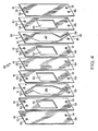
- an alternate preferred cell unit or module 52 which comprises a single divided cell also employing the preferred distributor plate 11 discussed above.
- the additions to this cell arrangement besides distributor plates 11 and electrode plates 53 are four spacer plates 54 and a central divider or separator plate 55, such as a selectively permeable membrane, which separates the adjacent catholyte and anolyte electrolysis compartments represented by numerals 56 and 57.
- Spacer plates 54 and separator plate 55 all have first holes 58 and second holes 61 which align and mate with the corresponding holes in the distributor and electrode plates.
- Spacer plates 54 also include a central openings 62 which is approximately equal in size to adjacent openings 15 in the distributor plates thereby enlarging the depth or thickness of the individual reaction chambers.
- the spacer plates 54 can be any thickness, although the desired total separation of juxtaposed electrodes within each cell unit must be considered with regard to overall cell efficiency.
- the spacers are generally preferred to be less than about 2 inches in thickness as with the preferred distributor plates.
- the spacer and distributor plates can be formed from a single thickness or sheet such that the formed distribution channel means 14 do not go completely through this combined plate throughout its length.
- one or more of the four spacer plates 54 in FIG. 4 can be removed or its dimensions varied without altering the essential function of the applicant's divided cell.
- the spacer plates can be of virtually any construction, with preferred plates 54 in the applicant's work being rectangular and of the same material indicated previously for preferred distributor plates 11.
- the single divided cell 52 shown in FIG. 4 highlights the importance of the symmetry described above in the applicant's preferred structures. All components of cell unit 52 are interchangeable with corresponding components without any loss in function.
- the internal manifold system in the applicant's design functions to channel electrolyte through corresponding cathode and anode compartments by means of the aligned holes in adjacent plates. Differing solutions have been used in the respective catholyte and anolyte compartments 56 and 57 simply by rotating the second distributor plate indicated by numeral 63 in the drawing to align its first holes 58 with the series of second holes 61 in the adjoining spacer, separator, and electrode plates.
- cell unit 52 can be repeated as many times as physically possible in arranging a multi-unit filter press cell bank.
- the terminal electrode plates in the bank can include some capping or plugging of appropriate holes 58 and 61 to seal off the ends of the individual flow paths for the catholyte and anolyte solutions.
- Multiple compartment cells having more than two chambers, which are suitable for desalination and other processes, can also be formed by repeating units of the applicant's distributor plate 11 with or without spacer plates 54 and with several separator plates 55, and then by utilizing three or more separate sets of holes and fluid channel means as described above.
- a further alternate embodiment which adds to the versatility of the applicant's invention is that his cell units are readily adapted to a packed bed arrangement which significantly increases the effective electrode area, production rate, mass transport, heat transport, and resulting efficiency for a given electrolysis reaction.
- ESA enhanced surface-area
- other types of enhanced surface-area (ESA) electrodes can also be employed with the applicant's cell design to realize these benefits. Since the general operation and construction of packed-bed cells is known to those skilled in the art, specific means will not be discussed in detail. Significantly, the applicant is not aware of any prior art method or device which combines this known packed-bed technology with a thin sheet filter press cell arrangement as in his invention.
- An optional interelectrode plate would be a flat plate inserted between the electrodes of adjacent cells also having a feeder tube from the plate edge to a point near where the top of the central cavity would be located.
- a mating hole in the face of this plate and the adjoining electrode plate would form an L-shaped feeder tube for introducing particulate matter through the electrode plate into the central cell chamber.
Landscapes
- Chemical & Material Sciences (AREA)
- Engineering & Computer Science (AREA)
- Electrochemistry (AREA)
- Chemical Kinetics & Catalysis (AREA)
- Sustainable Development (AREA)
- Sustainable Energy (AREA)
- Life Sciences & Earth Sciences (AREA)
- Manufacturing & Machinery (AREA)
- General Chemical & Material Sciences (AREA)
- Materials Engineering (AREA)
- Metallurgy (AREA)
- Organic Chemistry (AREA)
- Electrolytic Production Of Non-Metals, Compounds, Apparatuses Therefor (AREA)
Priority Applications (1)
| Application Number | Priority Date | Filing Date | Title |
|---|---|---|---|
| EP89109250A EP0334394A1 (fr) | 1983-03-21 | 1984-03-20 | Cellule électrochimique du type filtre presse présentant un système de distribution de fluides |
Applications Claiming Priority (3)
| Application Number | Priority Date | Filing Date | Title |
|---|---|---|---|
| US47752983A | 1983-03-21 | 1983-03-21 | |
| EP89109250A EP0334394A1 (fr) | 1983-03-21 | 1984-03-20 | Cellule électrochimique du type filtre presse présentant un système de distribution de fluides |
| US477529 | 1995-06-07 |
Related Parent Applications (1)
| Application Number | Title | Priority Date | Filing Date |
|---|---|---|---|
| EP84301883.9 Division | 1984-03-20 |
Publications (1)
| Publication Number | Publication Date |
|---|---|
| EP0334394A1 true EP0334394A1 (fr) | 1989-09-27 |
Family
ID=26120211
Family Applications (1)
| Application Number | Title | Priority Date | Filing Date |
|---|---|---|---|
| EP89109250A Withdrawn EP0334394A1 (fr) | 1983-03-21 | 1984-03-20 | Cellule électrochimique du type filtre presse présentant un système de distribution de fluides |
Country Status (1)
| Country | Link |
|---|---|
| EP (1) | EP0334394A1 (fr) |
Citations (5)
| Publication number | Priority date | Publication date | Assignee | Title |
|---|---|---|---|---|
| DE1421051A1 (de) * | 1958-03-18 | 1969-06-26 | Ici Ltd | Mehrfachelektrolysezelle |
| US4233146A (en) * | 1979-03-09 | 1980-11-11 | Allied Chemical Corporation | Cell flow distributors |
| US4339324A (en) * | 1980-12-03 | 1982-07-13 | Henes Products Corp. | Polycell gas generator |
| GB2093263A (en) * | 1981-02-12 | 1982-08-25 | Inst Francais Du Petrole | Fuel Cell Blocks |
| US4425215A (en) * | 1982-09-27 | 1984-01-10 | Henes Products Corp. | Gas generator |
-
1984
- 1984-03-20 EP EP89109250A patent/EP0334394A1/fr not_active Withdrawn
Patent Citations (5)
| Publication number | Priority date | Publication date | Assignee | Title |
|---|---|---|---|---|
| DE1421051A1 (de) * | 1958-03-18 | 1969-06-26 | Ici Ltd | Mehrfachelektrolysezelle |
| US4233146A (en) * | 1979-03-09 | 1980-11-11 | Allied Chemical Corporation | Cell flow distributors |
| US4339324A (en) * | 1980-12-03 | 1982-07-13 | Henes Products Corp. | Polycell gas generator |
| GB2093263A (en) * | 1981-02-12 | 1982-08-25 | Inst Francais Du Petrole | Fuel Cell Blocks |
| US4425215A (en) * | 1982-09-27 | 1984-01-10 | Henes Products Corp. | Gas generator |
Non-Patent Citations (1)
| Title |
|---|
| JOURNAL OF CHEMICAL TECHNOLOGY AND BIOTECHNOLOGY, vol. 30, no. 12, December 1980, pages 711-720, Society of Chemical Industry, Oxford, GB; M.D. BIRKETT et al.: "Design concepts and construction of bipolar filterpress cells" * |
Similar Documents
| Publication | Publication Date | Title |
|---|---|---|
| US4589968A (en) | Filter press electrochemical cell with improved fluid distribution system | |
| US6080290A (en) | Mono-polar electrochemical system with a double electrode plate | |
| US4339324A (en) | Polycell gas generator | |
| US4274939A (en) | Electrode package and use thereof | |
| US6193869B1 (en) | Modular apparatus for the demineralization of liquids | |
| US4124478A (en) | Thin sheet apparatus and a fluid flow device | |
| EP0501567A1 (fr) | Distributeur à section allant en diminuant pour batteries nécessitant une circulation forcée d'électrolyte | |
| WO2001011112A1 (fr) | Cellules electrolytiques presentant une capacite d'adhesion au liquide amelioree | |
| US4425215A (en) | Gas generator | |
| EP0122736B1 (fr) | Cellule électrochimique du type filtre-presse présentant un système de distribution de fluides | |
| US6878244B2 (en) | Filter-press type electrochemical reactor with bush inserts | |
| US2784158A (en) | Multiple ion exchange membrane electrodialysis cell | |
| JPH10121284A5 (fr) | ||
| US5637204A (en) | End casing for an electrodialyzer electrodialyzer equipped with such a casing and use of the said electrodialyzer | |
| US3746578A (en) | Fuel cell battery | |
| US6187155B1 (en) | Electrolytic cell separator assembly | |
| JPS6386884A (ja) | 電解槽およびそれに使用するガスケツト | |
| EP0334394A1 (fr) | Cellule électrochimique du type filtre presse présentant un système de distribution de fluides | |
| DE19740673C2 (de) | Elektrolyseapparat | |
| CN111139496A (zh) | 适于中部进液的电解室及其电解槽 | |
| US7101468B1 (en) | End box of an electrodialyser, electrodialyser comprising same and electrodialysis method | |
| US3421996A (en) | Batteries of electrochemical cells containing electrolyte metering tubes | |
| US4358357A (en) | Apparatus for the electrolysis of water | |
| WO2024155380A1 (fr) | Systèmes et procédés de génération électrochimique d'acide et base | |
| US5192411A (en) | Electrode for electrochemical reactors |
Legal Events
| Date | Code | Title | Description |
|---|---|---|---|
| PUAI | Public reference made under article 153(3) epc to a published international application that has entered the european phase |
Free format text: ORIGINAL CODE: 0009012 |
|
| 17P | Request for examination filed |
Effective date: 19890616 |
|
| AC | Divisional application: reference to earlier application |
Ref document number: 122736 Country of ref document: EP |
|
| AK | Designated contracting states |
Kind code of ref document: A1 Designated state(s): BE CH DE FR GB IT LI NL |
|
| RAP1 | Party data changed (applicant data changed or rights of an application transferred) |
Owner name: REILLY INDUSTRIES, INC. |
|
| 17Q | First examination report despatched |
Effective date: 19911209 |
|
| STAA | Information on the status of an ep patent application or granted ep patent |
Free format text: STATUS: THE APPLICATION IS DEEMED TO BE WITHDRAWN |
|
| 18D | Application deemed to be withdrawn |
Effective date: 19940607 |