EP0501567A1 - Distributeur à section allant en diminuant pour batteries nécessitant une circulation forcée d'électrolyte - Google Patents
Distributeur à section allant en diminuant pour batteries nécessitant une circulation forcée d'électrolyte Download PDFInfo
- Publication number
- EP0501567A1 EP0501567A1 EP92200465A EP92200465A EP0501567A1 EP 0501567 A1 EP0501567 A1 EP 0501567A1 EP 92200465 A EP92200465 A EP 92200465A EP 92200465 A EP92200465 A EP 92200465A EP 0501567 A1 EP0501567 A1 EP 0501567A1
- Authority
- EP
- European Patent Office
- Prior art keywords
- cross
- manifold
- section
- outlet
- inlet
- Prior art date
- Legal status (The legal status is an assumption and is not a legal conclusion. Google has not performed a legal analysis and makes no representation as to the accuracy of the status listed.)
- Ceased
Links
- 239000003792 electrolyte Substances 0.000 title claims abstract description 31
- 230000007797 corrosion Effects 0.000 description 3
- 238000005260 corrosion Methods 0.000 description 3
- 239000000047 product Substances 0.000 description 3
- 239000013535 sea water Substances 0.000 description 3
- 230000003247 decreasing effect Effects 0.000 description 2
- 238000003487 electrochemical reaction Methods 0.000 description 2
- UFHFLCQGNIYNRP-UHFFFAOYSA-N Hydrogen Chemical compound [H][H] UFHFLCQGNIYNRP-UHFFFAOYSA-N 0.000 description 1
- FYYHWMGAXLPEAU-UHFFFAOYSA-N Magnesium Chemical compound [Mg] FYYHWMGAXLPEAU-UHFFFAOYSA-N 0.000 description 1
- 229910021607 Silver chloride Inorganic materials 0.000 description 1
- 239000006227 byproduct Substances 0.000 description 1
- 230000000295 complement effect Effects 0.000 description 1
- 238000010276 construction Methods 0.000 description 1
- 238000009826 distribution Methods 0.000 description 1
- 239000012530 fluid Substances 0.000 description 1
- 239000007788 liquid Substances 0.000 description 1
- 239000011777 magnesium Substances 0.000 description 1
- 229910001629 magnesium chloride Inorganic materials 0.000 description 1
- 239000000463 material Substances 0.000 description 1
- 238000009828 non-uniform distribution Methods 0.000 description 1
- HKZLPVFGJNLROG-UHFFFAOYSA-M silver monochloride Chemical compound [Cl-].[Ag+] HKZLPVFGJNLROG-UHFFFAOYSA-M 0.000 description 1
- 238000009827 uniform distribution Methods 0.000 description 1
Images

Classifications
-
- H—ELECTRICITY
- H01—ELECTRIC ELEMENTS
- H01M—PROCESSES OR MEANS, e.g. BATTERIES, FOR THE DIRECT CONVERSION OF CHEMICAL ENERGY INTO ELECTRICAL ENERGY
- H01M50/00—Constructional details or processes of manufacture of the non-active parts of electrochemical cells other than fuel cells, e.g. hybrid cells
- H01M50/70—Arrangements for stirring or circulating the electrolyte
- H01M50/77—Arrangements for stirring or circulating the electrolyte with external circulating path
-
- H—ELECTRICITY
- H01—ELECTRIC ELEMENTS
- H01M—PROCESSES OR MEANS, e.g. BATTERIES, FOR THE DIRECT CONVERSION OF CHEMICAL ENERGY INTO ELECTRICAL ENERGY
- H01M6/00—Primary cells; Manufacture thereof
- H01M6/30—Deferred-action cells
- H01M6/32—Deferred-action cells activated through external addition of electrolyte or of electrolyte components
- H01M6/34—Immersion cells, e.g. sea-water cells
Definitions
- the present invention relates generally to batteries requiring forced flow of electrolyte and, more particularly, to a novel manifold design for the inlet and outlet of such a battery which results in more uniform distribution of the flow of electrolyte through the battery, thus providing longer battery life.
- Forced electrolyte flow batteries are employed, for example, to provide power to electrical equipment in underwater environments, in which batteries the electrolyte is seawater pumped between the plates of the batteries.
- the battery for use in such applications is the magnesium/silver chloride battery.
- the battery consists of a number of cell plates closely stacked in parallel with electrolyte entering via an inlet manifold, flowing past the plates through the inter-plate spaces, and exiting via an outlet manifold.
- the seawater electrolyte is forced past the plates from bottom to top in order to complement the natural upward flow of the hydrogen gas which is produced along with the aforementioned corrosion products as a by-product of the electrochemical reaction.
- the present invention achieves the above objects, among others, by providing, in a preferred embodiment, inlet and outlet manifolds for a forced electrolyte flow battery, the manifolds having nonuniform cross-sections.
- the inlet manifold extends along the base of the battery cells and tapers from a large cross-section at the inlet end thereof to a small cross-section at the closed opposite end of the manifold.
- the outlet manifold has electrolyte outlets at either end of the manifold and tapers from a small cross-section at the middle of the manifold to large cross-sections at the electrolyte outlets of the manifolds.
- the inlet and outlets to and from the inlet and outlet manifolds are arranged, respectively, such that the header connected to the inlet manifold is larger in cross-section than the cross-section of the inlet manifold at that point and the headers connected to the outlet manifold are larger in cross-section than the cross-sections of the outlet manifold at that point.
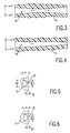
- Figure 1 illustrates a forced electrolyte flow battery, generally indicated by the reference numeral 10, which includes a stack of a plurality of vertical, closely spaced apart plates, as at 12, or stack, disposed within a cylindrical shell 14.
- an elongate outlet manifold 30 Disposed at the upper edges of plates 12 is an elongate outlet manifold 30 comprising a channel extending orthogonally therealong and formed in an upper manifold block 31 to carry electrolyte from the plates for discharge through outlet headers 32 and 34.
- headers 22, 32, and 34 have the same cross-sections as the manifold connections to which they are attached, or larger cross-sections (as indicated on Figure 1), in order to minimize turbulence within manifolds 20 and 30. It has been found that such turbulence can hinder or prevent flow past plates 12 where it occurs.
- inlet manifold 20 is tapered, with the largest cross-section at the inlet end and with the cross-section of the manifold decreasing uniformly to the closed opposite end. This configuration accommodates a greater volume of fluid at the input end and, due to the decreasing cross-sectional area, tends to force an increase in pressure toward the blocked end, compensating for frictional losses.
- Outlet manifold 30 has its smallest cross-sectional area at the middle thereof and the manifold tapers therefrom to the two outlet ends, thus accommodating the greater volume of liquid as each intercell space discharges electrolyte into the manifold.
- Both inlet and outlet manifolds 20 and 30 are shown as being of rectilinear form; however, such is not required for practising the present invention.
- the invention contemplates only that the manifolds taper generally proportionally to the varying flow rate of electrolyte along the manifolds.
- Manifold blocks 21 and 31 may be conveniently formed from a suitable polymeric material with manifolds 20 and 30 milled therein.
Landscapes
- Chemical & Material Sciences (AREA)
- Chemical Kinetics & Catalysis (AREA)
- Electrochemistry (AREA)
- General Chemical & Material Sciences (AREA)
- Engineering & Computer Science (AREA)
- Manufacturing & Machinery (AREA)
- Fuel Cell (AREA)
- Hybrid Cells (AREA)
- Filling, Topping-Up Batteries (AREA)
- Primary Cells (AREA)
Applications Claiming Priority (2)
| Application Number | Priority Date | Filing Date | Title |
|---|---|---|---|
| US659647 | 1991-02-25 | ||
| US07/659,647 US5188911A (en) | 1991-02-25 | 1991-02-25 | Tapered manifold for batteries requiring forced electrolyte flow |
Publications (1)
| Publication Number | Publication Date |
|---|---|
| EP0501567A1 true EP0501567A1 (fr) | 1992-09-02 |
Family
ID=24646219
Family Applications (1)
| Application Number | Title | Priority Date | Filing Date |
|---|---|---|---|
| EP92200465A Ceased EP0501567A1 (fr) | 1991-02-25 | 1992-02-18 | Distributeur à section allant en diminuant pour batteries nécessitant une circulation forcée d'électrolyte |
Country Status (3)
| Country | Link |
|---|---|
| US (1) | US5188911A (fr) |
| EP (1) | EP0501567A1 (fr) |
| JP (1) | JPH0562667A (fr) |
Cited By (4)
| Publication number | Priority date | Publication date | Assignee | Title |
|---|---|---|---|---|
| WO2013095424A1 (fr) * | 2011-12-21 | 2013-06-27 | Alstom Technology Ltd | Collecteurs de forme optimisée et leurs procédés de fabrication |
| US8573252B2 (en) | 2010-11-30 | 2013-11-05 | Alstom Technology Ltd | Shape optimized headers and methods of manufacture thereof |
| WO2018115193A3 (fr) * | 2016-12-22 | 2018-09-27 | Innenco International Ab | Système de distribution d'énergie et distributeur du système et procédé de pose du système |
| CN117727991A (zh) * | 2024-02-08 | 2024-03-19 | 浙江海盐力源环保科技股份有限公司 | 新型电堆结构 |
Families Citing this family (56)
| Publication number | Priority date | Publication date | Assignee | Title |
|---|---|---|---|---|
| FR2770339B1 (fr) | 1997-10-27 | 2003-06-13 | Commissariat Energie Atomique | Structure munie de contacts electriques formes a travers le substrat de cette structure et procede d'obtention d'une telle structure |
| US6162555A (en) * | 1999-07-15 | 2000-12-19 | Metallic Power, Inc. | Particle feeding apparatus for electrochemical power source and method of making same |
| US6296958B1 (en) | 2000-03-08 | 2001-10-02 | Metallic Power, Inc. | Refuelable electrochemical power source capable of being maintained in a substantially constant full condition and method of using the same |
| US6432292B1 (en) | 2000-05-16 | 2002-08-13 | Metallic Power, Inc. | Method of electrodepositing metal on electrically conducting particles |
| US6522955B1 (en) | 2000-07-28 | 2003-02-18 | Metallic Power, Inc. | System and method for power management |
| US20030035984A1 (en) | 2001-08-15 | 2003-02-20 | Colborn Jeffrey A. | Metal fuel cell system for providing backup power to one or more loads |
| US6689711B2 (en) | 2001-10-09 | 2004-02-10 | Metallic Power, Inc. | Methods of producing oxygen reduction catalyst |
| US6679280B1 (en) | 2001-10-19 | 2004-01-20 | Metallic Power, Inc. | Manifold for fuel cell system |
| US6911274B1 (en) | 2001-10-19 | 2005-06-28 | Metallic Power, Inc. | Fuel cell system |
| US6873157B2 (en) * | 2002-04-04 | 2005-03-29 | Metallic Power, Inc. | Method of and system for determining the remaining energy in a metal fuel cell |
| US6764588B2 (en) * | 2002-05-17 | 2004-07-20 | Metallic Power, Inc. | Method of and system for flushing one or more cells in a particle-based electrochemical power source in standby mode |
| US6942105B2 (en) * | 2002-05-17 | 2005-09-13 | Metallic Power, Inc. | In-line filtration for a particle-based electrochemical power system |
| US6787260B2 (en) * | 2002-09-12 | 2004-09-07 | Metallic Power, Inc. | Electrolyte-particulate fuel cell anode |
| US7361427B1 (en) * | 2005-05-27 | 2008-04-22 | The United States Of America Represented By The Secretary Of The Navy | Manifold for a pile configured battery |
| ES2263394B1 (es) * | 2006-02-01 | 2007-11-16 | Sener, Ingenieria Y Sistemas, S.A. | Colector de seccion transversal variable y pared delgada para paneles de absorcion solar. |
| US7855005B2 (en) * | 2007-02-12 | 2010-12-21 | Deeya Energy, Inc. | Apparatus and methods of determination of state of charge in a redox flow battery |
| US20100173209A1 (en) * | 2007-07-18 | 2010-07-08 | Sundar Jayaraman | Fuel cell two-phase coolant exit manifold |
| US8587150B2 (en) * | 2008-02-28 | 2013-11-19 | Deeya Energy, Inc. | Method and modular system for charging a battery |
| US7927731B2 (en) * | 2008-07-01 | 2011-04-19 | Deeya Energy, Inc. | Redox flow cell |
| US8785023B2 (en) * | 2008-07-07 | 2014-07-22 | Enervault Corparation | Cascade redox flow battery systems |
| US7820321B2 (en) * | 2008-07-07 | 2010-10-26 | Enervault Corporation | Redox flow battery system for distributed energy storage |
| EP2311119B1 (fr) * | 2008-08-22 | 2018-02-21 | RedFlow R&D Pty Ltd | Collecteur intégré |
| US8236463B2 (en) * | 2008-10-10 | 2012-08-07 | Deeya Energy, Inc. | Magnetic current collector |
| WO2010042900A1 (fr) * | 2008-10-10 | 2010-04-15 | Deeya Energy Technologies, Inc. | Procédés pour fixer des membranes flexibles poreuses en utilisant un solvant |
| US8231993B2 (en) * | 2008-10-10 | 2012-07-31 | Deeya Energy, Inc. | Flexible multi-walled tubing assembly |
| US8230736B2 (en) * | 2008-10-10 | 2012-07-31 | Deeya Energy, Inc. | Level sensor for conductive liquids |
| US20100092843A1 (en) * | 2008-10-10 | 2010-04-15 | Deeya Energy Technologies, Inc. | Venturi pumping system in a hydrogen gas circulation of a flow battery |
| CN102246338B (zh) * | 2008-10-10 | 2014-06-11 | 迪亚能源股份有限公司 | 液流电池元电池的热控制 |
| EP2351184A4 (fr) * | 2008-10-10 | 2014-07-09 | Deeya Energy Technologies Inc | Procédé et appareil permettant d établir l état de charge d une batterie |
| US20110079074A1 (en) * | 2009-05-28 | 2011-04-07 | Saroj Kumar Sahu | Hydrogen chlorine level detector |
| CN102460812B (zh) * | 2009-05-28 | 2014-12-31 | 艾默吉电力系统股份有限公司 | 由原料制备流通电池电解质 |
| US8587255B2 (en) * | 2009-05-28 | 2013-11-19 | Deeya Energy, Inc. | Control system for a flow cell battery |
| EP2436080A2 (fr) * | 2009-05-28 | 2012-04-04 | Deeya Energy, Inc. | Compositions d'électrolyte |
| CN102460811B (zh) * | 2009-05-28 | 2015-11-25 | 艾默吉电力系统股份有限公司 | 氧化还原流通单元电池再平衡 |
| US8723489B2 (en) * | 2009-05-28 | 2014-05-13 | Deeya Energy, Inc. | Bi-directional buck-boost circuit |
| US8349477B2 (en) * | 2009-05-28 | 2013-01-08 | Deeya Energy, Inc. | Optical leak detection sensor |
| US8551299B2 (en) * | 2009-05-29 | 2013-10-08 | Deeya Energy, Inc. | Methods of producing hydrochloric acid from hydrogen gas and chlorine gas |
| US8951665B2 (en) * | 2010-03-10 | 2015-02-10 | Imergy Power Systems, Inc. | Methods for the preparation of electrolytes for chromium-iron redox flow batteries |
| US9281535B2 (en) | 2010-08-12 | 2016-03-08 | Imergy Power Systems, Inc. | System dongle |
| US8980484B2 (en) | 2011-03-29 | 2015-03-17 | Enervault Corporation | Monitoring electrolyte concentrations in redox flow battery systems |
| US8916281B2 (en) | 2011-03-29 | 2014-12-23 | Enervault Corporation | Rebalancing electrolytes in redox flow battery systems |
| DE102012011328A1 (de) * | 2012-06-06 | 2013-12-12 | Linde Aktiengesellschaft | Wärmeübertrager |
| WO2014200482A1 (fr) * | 2013-06-13 | 2014-12-18 | United Technologies Corporation | Batterie à flux à passage de collecteurs qui varie en section transversale |
| US10418647B2 (en) | 2015-04-15 | 2019-09-17 | Lockheed Martin Energy, Llc | Mitigation of parasitic reactions within flow batteries |
| KR20180042852A (ko) | 2015-08-19 | 2018-04-26 | 록히드 마틴 에너지, 엘엘씨 | 플로우 배터리 내의 고형물 저감 방법 |
| US10381674B2 (en) | 2016-04-07 | 2019-08-13 | Lockheed Martin Energy, Llc | High-throughput manufacturing processes for making electrochemical unit cells and electrochemical unit cells produced using the same |
| US10147957B2 (en) | 2016-04-07 | 2018-12-04 | Lockheed Martin Energy, Llc | Electrochemical cells having designed flow fields and methods for producing the same |
| US10109879B2 (en) | 2016-05-27 | 2018-10-23 | Lockheed Martin Energy, Llc | Flow batteries having an electrode with a density gradient and methods for production and use thereof |
| US10403911B2 (en) | 2016-10-07 | 2019-09-03 | Lockheed Martin Energy, Llc | Flow batteries having an interfacially bonded bipolar plate-electrode assembly and methods for production and use thereof |
| US10573899B2 (en) | 2016-10-18 | 2020-02-25 | Lockheed Martin Energy, Llc | Flow batteries having an electrode with differing hydrophilicity on opposing faces and methods for production and use thereof |
| US10581104B2 (en) | 2017-03-24 | 2020-03-03 | Lockheed Martin Energy, Llc | Flow batteries having a pressure-balanced electrochemical cell stack and associated methods |
| US11056698B2 (en) | 2018-08-02 | 2021-07-06 | Raytheon Technologies Corporation | Redox flow battery with electrolyte balancing and compatibility enabling features |
| CN111426220B (zh) * | 2020-04-02 | 2025-05-27 | 广东芬尼克兹节能设备有限公司 | 一种集成管式换热器 |
| US11271226B1 (en) | 2020-12-11 | 2022-03-08 | Raytheon Technologies Corporation | Redox flow battery with improved efficiency |
| FR3124348B1 (fr) * | 2021-06-22 | 2023-10-20 | Valeo Systemes Thermiques | Dispositif de régulation thermique pour système électronique |
| CN118676411B (zh) * | 2024-08-21 | 2024-11-08 | 中海储能科技(北京)有限公司 | 一种带有一体式流道板结构的液流电池电堆 |
Citations (5)
| Publication number | Priority date | Publication date | Assignee | Title |
|---|---|---|---|---|
| US3388003A (en) * | 1966-07-28 | 1968-06-11 | Navy Usa | Seawater battery with electrodes in decreasing passage areas |
| FR2117973A1 (fr) * | 1970-12-09 | 1972-07-28 | Deutsche Automobilgesellsch | |
| US3926676A (en) * | 1971-02-25 | 1975-12-16 | Siemens Ag | Battery comprising a plurality of cells |
| EP0149448A2 (fr) * | 1983-12-19 | 1985-07-24 | S.E.A. Studiengesellschaft für Energiespeicher und Antriebssysteme Gesellschaft m.b.H. | Elément galvanique, en particulier élément secondaire et méthode de fabrication |
| EP0167517A1 (fr) * | 1984-06-06 | 1986-01-08 | S.E.A. Studiengesellschaft für Energiespeicher und Antriebssysteme Gesellschaft m.b.H. | Elément galvanique |
Family Cites Families (3)
| Publication number | Priority date | Publication date | Assignee | Title |
|---|---|---|---|---|
| US916320A (en) * | 1908-07-17 | 1909-03-23 | Henry Francis Joel | Secondary battery. |
| US4072801A (en) * | 1977-04-04 | 1978-02-07 | Globe-Union Inc. | Deferred action battery having improved bottom port cover |
| FR2592991B1 (fr) * | 1986-01-16 | 1988-03-04 | Accumulateurs Fixes | Dispositif echangeur thermique pour pile amorcable. |
-
1991
- 1991-02-25 US US07/659,647 patent/US5188911A/en not_active Expired - Fee Related
-
1992
- 1992-02-18 EP EP92200465A patent/EP0501567A1/fr not_active Ceased
- 1992-02-24 JP JP4036331A patent/JPH0562667A/ja active Pending
Patent Citations (5)
| Publication number | Priority date | Publication date | Assignee | Title |
|---|---|---|---|---|
| US3388003A (en) * | 1966-07-28 | 1968-06-11 | Navy Usa | Seawater battery with electrodes in decreasing passage areas |
| FR2117973A1 (fr) * | 1970-12-09 | 1972-07-28 | Deutsche Automobilgesellsch | |
| US3926676A (en) * | 1971-02-25 | 1975-12-16 | Siemens Ag | Battery comprising a plurality of cells |
| EP0149448A2 (fr) * | 1983-12-19 | 1985-07-24 | S.E.A. Studiengesellschaft für Energiespeicher und Antriebssysteme Gesellschaft m.b.H. | Elément galvanique, en particulier élément secondaire et méthode de fabrication |
| EP0167517A1 (fr) * | 1984-06-06 | 1986-01-08 | S.E.A. Studiengesellschaft für Energiespeicher und Antriebssysteme Gesellschaft m.b.H. | Elément galvanique |
Cited By (7)
| Publication number | Priority date | Publication date | Assignee | Title |
|---|---|---|---|---|
| US8573252B2 (en) | 2010-11-30 | 2013-11-05 | Alstom Technology Ltd | Shape optimized headers and methods of manufacture thereof |
| WO2013095424A1 (fr) * | 2011-12-21 | 2013-06-27 | Alstom Technology Ltd | Collecteurs de forme optimisée et leurs procédés de fabrication |
| CN104024731A (zh) * | 2011-12-21 | 2014-09-03 | 阿尔斯通技术有限公司 | 形状优化集管及其制造方法 |
| JP2015507164A (ja) * | 2011-12-21 | 2015-03-05 | アルストム テクノロジー リミテッドALSTOM Technology Ltd | 形状が最適化されたヘッダおよびその製造方法 |
| CN104024731B (zh) * | 2011-12-21 | 2017-01-18 | 通用电器技术有限公司 | 形状优化集管及其制造方法 |
| WO2018115193A3 (fr) * | 2016-12-22 | 2018-09-27 | Innenco International Ab | Système de distribution d'énergie et distributeur du système et procédé de pose du système |
| CN117727991A (zh) * | 2024-02-08 | 2024-03-19 | 浙江海盐力源环保科技股份有限公司 | 新型电堆结构 |
Also Published As
| Publication number | Publication date |
|---|---|
| JPH0562667A (ja) | 1993-03-12 |
| US5188911A (en) | 1993-02-23 |
Similar Documents
| Publication | Publication Date | Title |
|---|---|---|
| EP0501567A1 (fr) | Distributeur à section allant en diminuant pour batteries nécessitant une circulation forcée d'électrolyte | |
| JP7203451B2 (ja) | 電解液の分散が改善された電極組立体およびフロー電池 | |
| DE69301810T2 (de) | Akkumulatorsystem | |
| CA1092646A (fr) | Element d'electrode bipolaire en peigne et pile de batteries connexe | |
| US4339324A (en) | Polycell gas generator | |
| EP0198483A2 (fr) | Cellule électrochimique planaire à jonctions multiples | |
| US6524453B1 (en) | Electrode assembly | |
| MY116084A (en) | Electrodeionization apparatus. | |
| EP2124283A1 (fr) | Pile à combustible | |
| JPS62500337A (ja) | 分離状態が改良された燃料電池 | |
| DE19539959C2 (de) | Brennstoffzellenanordnung | |
| EP3553864B1 (fr) | Plaque bipolaire, empilement de cellules et batterie à flux rédox | |
| US6117583A (en) | Lead battery | |
| US11081706B2 (en) | Fuel cell stack | |
| US3953238A (en) | Multicell seawater battery | |
| US6846393B2 (en) | Electrolysis cells | |
| CN218677229U (zh) | 电堆进液板及其适用的液流电池 | |
| US4074020A (en) | Cross-feed fuel cell battery with filter press type structure of polygonal cross-section | |
| US3432353A (en) | Fuel cell electrode | |
| US7101468B1 (en) | End box of an electrodialyser, electrodialyser comprising same and electrodialysis method | |
| US4421831A (en) | Battery flow restrictor | |
| EP0131173B1 (fr) | Appareil d'électrolyse | |
| US4288507A (en) | Control of edge effects of oxidant electrode | |
| CA1164935A (fr) | Accumulateur active a l'eau de mer | |
| Stalnaker et al. | Design and assembly considerations for redox cells and stacks |
Legal Events
| Date | Code | Title | Description |
|---|---|---|---|
| PUAI | Public reference made under article 153(3) epc to a published international application that has entered the european phase |
Free format text: ORIGINAL CODE: 0009012 |
|
| AK | Designated contracting states |
Kind code of ref document: A1 Designated state(s): DE FR GB |
|
| 17P | Request for examination filed |
Effective date: 19930223 |
|
| 17Q | First examination report despatched |
Effective date: 19940805 |
|
| STAA | Information on the status of an ep patent application or granted ep patent |
Free format text: STATUS: THE APPLICATION HAS BEEN REFUSED |
|
| 18R | Application refused |
Effective date: 19951112 |