EP0334548A2 - Dispositif pour assurer l'égalité d'une feuille de papier et l'espacement entre le papier et le traceur pendant l'impression - Google Patents
Dispositif pour assurer l'égalité d'une feuille de papier et l'espacement entre le papier et le traceur pendant l'impression Download PDFInfo
- Publication number
- EP0334548A2 EP0334548A2 EP89302573A EP89302573A EP0334548A2 EP 0334548 A2 EP0334548 A2 EP 0334548A2 EP 89302573 A EP89302573 A EP 89302573A EP 89302573 A EP89302573 A EP 89302573A EP 0334548 A2 EP0334548 A2 EP 0334548A2
- Authority
- EP
- European Patent Office
- Prior art keywords
- sheet
- spacer
- printer according
- printed
- pen
- Prior art date
- Legal status (The legal status is an assumption and is not a legal conclusion. Google has not performed a legal analysis and makes no representation as to the accuracy of the status listed.)
- Granted
Links
Images
Classifications
-
- B—PERFORMING OPERATIONS; TRANSPORTING
- B41—PRINTING; LINING MACHINES; TYPEWRITERS; STAMPS
- B41J—TYPEWRITERS; SELECTIVE PRINTING MECHANISMS, i.e. MECHANISMS PRINTING OTHERWISE THAN FROM A FORME; CORRECTION OF TYPOGRAPHICAL ERRORS
- B41J25/00—Actions or mechanisms not otherwise provided for
- B41J25/304—Bodily-movable mechanisms for print heads or carriages movable towards or from paper surface
- B41J25/308—Bodily-movable mechanisms for print heads or carriages movable towards or from paper surface with print gap adjustment mechanisms
- B41J25/3082—Bodily-movable mechanisms for print heads or carriages movable towards or from paper surface with print gap adjustment mechanisms with print gap adjustment means on the print head carriage, e.g. for rotation around a guide bar or using a rotatable eccentric bearing
-
- B—PERFORMING OPERATIONS; TRANSPORTING
- B41—PRINTING; LINING MACHINES; TYPEWRITERS; STAMPS
- B41J—TYPEWRITERS; SELECTIVE PRINTING MECHANISMS, i.e. MECHANISMS PRINTING OTHERWISE THAN FROM A FORME; CORRECTION OF TYPOGRAPHICAL ERRORS
- B41J19/00—Character- or line-spacing mechanisms
-
- B—PERFORMING OPERATIONS; TRANSPORTING
- B41—PRINTING; LINING MACHINES; TYPEWRITERS; STAMPS
- B41J—TYPEWRITERS; SELECTIVE PRINTING MECHANISMS, i.e. MECHANISMS PRINTING OTHERWISE THAN FROM A FORME; CORRECTION OF TYPOGRAPHICAL ERRORS
- B41J25/00—Actions or mechanisms not otherwise provided for
- B41J25/304—Bodily-movable mechanisms for print heads or carriages movable towards or from paper surface
- B41J25/308—Bodily-movable mechanisms for print heads or carriages movable towards or from paper surface with print gap adjustment mechanisms
Definitions
- the present invention generally relates to printers and, more particularly, to improved paper holddown devices for printers.
- ink drops follow trajectories determined by the vector sum of the ink ejection velocity (Ve) and the velocity of the inking means (Vp).
- Ve ink ejection velocity
- Vp velocity of the inking means
- distance Dp is defined as the distance measured laterally along the surface of a printed sheet between the inking means and the intended location of ink dot placement on a sheet at the time of inkdrop ejection
- distance Ds is defined as the pen-to-sheet spacing as measured perpendicular to the sheet surface
- the ratio of Dp to Ds is proportional to the ratio of the velocity Vp to the velocity Ve.
- distance Dp remains constant whenever a sheet is being printed to avoid misalignment of printed characters; however, because pen-to-sheet distance Dp is a function of distance Ds, the latter distance must also remain constant to maintain accurate ink drop placement during printing.
- Ds pen-to-sheet spacing distance
- an inkjet pen prints a swath of ink drops while moving both from right-to-left and from left-to-right across the surface of a sheet.
- the printed sheet is indexed a swath width (e.g., about 3/8 inch). Because such printers provide ink dots in columns in each swath, print defects will appear unless dot columns on adjacent swaths are closely aligned.
- conventional inkjet printers are often unable to provide consistently acceptable print quality.
- the additive effect of manufacturing tolerances often cause pen-to-sheet spacing distance Ds to vary substantially more than desired.
- the spacing distance Ds in conventional inkjet printers can be affected by lack of flatness in carriage guides and paper support plates.
- ink dot placement during printing can vary because of variations in sheet thickness and because of curls and cockles in sheets.
- sheet thicknesses commonly used in printers vary from 45 ⁇ m to 157 ⁇ m.
- cockles can be present because of paper defects and because of moisture present during printing.
- sheet holddown devices such as electrostatic or suction devices.
- electrostatic holddown device paper flatness is maintained by establishing electrostatic attraction between a flat support plate on the printer and the back surface of a sheet to be printed.
- vacuum holddown devices sheet flatness is maintained by providing suction between a support plate and the back surface of a sheet to be printed. It should be noted that, in either type of holddown device, direct contact of the holddown device with the printed surface is avoided to minimize ink smearing and other adverse affects on print appearance.
- An object of the present invention is to provide improved paper holddown devices for use with printers.
- an object of the present invention is to improve printers, especially inkjet printers of the bidirectional printing type, by providing a device to accurately maintain pen-to-sheet spacing and sheet flatness during printing and, thereby, to minimize spacing deviations that cause misalignment in printed characters.
- the present invention generally provides a printer comprising an inking device that ejects ink drops for printing the surface of a sheet, and a spacer interposed between the inking means and the sheet surface to ride upon the surface being printed so as to maintain preselected spacing.
- the spacer is a generally L-shaped member whose leg is connected to the inking device and whose foot is positioned to extend parallel to the sheet surface to ride as a skid on the printed surface of the sheet.
- the spacer can be a skid, a wheel, a roller, or any other bearing-like device suited for supporting an inking device directly on a sheet with a preselected pen-to-sheet spacing.
- the device of the present invention provides substantial advantages over conventional holddown mechanisms in printers because it directly acts on the printed surface to assure paper flatness and spacing accuracy.
- devices according to the present invention maintain constant pen-to-sheet spacing even when paper thickness varies or when there are printer mechanism problems such as lack of flatness or straightness in carriage guide rods and paper support plates.
- the present invention simplifies printer design while increasing allowable manufacturing tolerances, thereby substantially reducing costs.
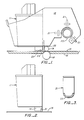
- FIGURE 1 shows a bidirectional inkjet printer includes an inkjet pen 11 that is held rigidly in a movable carriage 13 so that the pen nozzle 14 is above the surface of a sheet 15 which lays substantially flat on a stationary support plate 16. Further, the illustrated inkjet printer includes a drive roller 18 and a pinch roller 19 which are controlled to periodically index the sheet across the surface of plate 16. It should be understood that various systems for controlling sheet indexing are well known.
- carriage 13 is slidably journaled to a linear guide rod 20 by bearings 20A.
- Guide rod 20 is fixed to the printer chassis, not shown, to extend in the cross-direction parallel to the surface of sheet 15. (As used herein, the term “cross direction” refers to a direction perpendicular to the paper indexing direction.)
- Guide rod 20 and bearings 20A are designed to allow carriage 13 to move from side-to-side across the surface of a printed sheet but, in contrast to conventional inkjet printers, rotation of carriage 13 about rod 20 is not substantially restricted by the design of the rod or its bearings.
- an L-shaped spacer member is attached to carriage 13 with its foot 22 interposed between carriage 13 and sheet 15.
- the upper surface 23 of spacer 21 abuts the lower end of inkjet pen 11 adjacent nozzle 14 and, thus, provides a physical stop.
- spacer 21 extends substantially across the width of inkjet pen 11 and its lower surface 24 is generally planar to provide a broad face to ride upon sheet 15.
- stop surface 23 and riding surface 24 defines the desired spacing of inkjet nozzle 14 from the surface of sheet 15.
- spacer 21 have low contact friction with the surface of sheet 15 in both the cross-direction and in the indexing direction.
- Low contact friction in the cross-direction is required to facilitate back and forth travel of the inkjet pen, while low contact friction in the indexing direction is required to facilitate operation of the sheet transport device.
- the peripheral edges of riding surface 24 are arcuate.
- contact friction is reduced by the selection of the materials and the surface finish of riding surface 24.
- riding surface 24 can be polished chromeplate to minimize friction as well as to increase wear life.
- a device (not shown) can be provided to lift spacer 21 off the sheet during indexing; normally, such a lifting device is operative at the margins of the sheet.
- Another measure which can be taken to reduce contact friction is to provide an air bearing at the riding 24 surface of spacer 21.
- Such an air bearing is readily implemented by providing a source of pressurized gas and by forming appropriate holes or channels within riding surface 24 to allow the pressurized gas to escape between the riding surface and the face of sheet 15.
- the spacer can still be said to ride on the sheet surface, albeit via a cushion of pressurized gas.
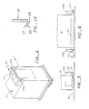
- FIGURES 2 through 4 show an alternative embodiment of the present invention in which a spacer 31 is attached to the body of inkjet pen 11 rather than to carriage 13. More particularly, spacer 31 is an elongated rail-like member that is mounted to extend parallel to the longitudinal axis of guide shaft 20 across the body of inkjet pen 11. As shown in cross-section in FIGURE 3, spacer 31 has a generally planar riding surface 33 with arcuate peripheral edges to accommodate movement in the indexing direction. Also, as shown in perspective in FIGURE 4, the spacer ends 37a and 37b are arcuate to accommodate movement in the cross-direction.
- FIGURES 5 and 6 show yet another alternative embodiment of the present invention.
- a roller-like spacer 51 is connected to carriage 13 by flanges 55a and 55b.
- the flanges accept an axle 57 which extends coaxially of the roller-like spacer to allow it to roll freely in the indexing direction.
- the ends of roller-like spacer 51 are arcuately curved so that it easily skids back and forth over the surface sheet 15 in the cross-direction.
- sheet 15 is held stationary by drive roller 18 while carriage 13 carries inkjet pen 11 back and forth across the sheet to print swaths of ink dots.
- roller 18 is driven so that sheet 15 is advanced in the direction indicated by the arrow over a distance equal to the swath width, and then carriage 13 again carries inkjet pen 11 across the sheet to print a second swath. This back-and-forth movement of carriage 13 is continued until the sheet is printed as desired.
- spacer 21 of FIGURE 1 slides across the printed surface of the sheet. Because of its proximity to the printed area, spacer 21 flattens the sheet at the localized area of printing.
- the force exerted by spacer 21 to flatten sheet 15 can be referred to as the contact force.
- the contact force is primarily determined by the weight distribution of inkjet pen 11 and carriage 13 relative to guide rod 20. That is, guide rod 20 acts as a fulcrum about which carriage 13 is pivoted.
- the net force, or torque, acting about rod 20 in the counterclockwise direction in FIGURE 1 depends upon the counterbalancing weight of the carriage on the opposite side of the rod. In practice, carriage 13 is mounted and balanced such that the contact force in the counterclockwise direction is sufficient to maintain the riding surface of spacer 21 in contact with the surface of sheet 15 and to assure substantial paper flatness under inkjet nozzle 14 without causing undue frictional drag.
- spacer 21 can exceed the localized force exerted by a conventional holddown device which operates upon the entire paper surface. Accordingly, spacer 21 can provide a flatter surface at the point of printing than conventional holddown devices. In practice, spacer 21 holds pen-to-sheet spacing constant within one to two thousands of an inch.
- spacers in FIGURES 2 through 6 are substantially the same as the operation of spacer 21 in FIGURE 1. That is, those spacers either slide or roll over the printed surface while concentrating the contact force over localized areas near the point of ink impact with sheet 15.
- the spacers can take various forms, including notatable ball-like shapes (not shown), as long as they are capable of supporting an inking device directly on the surface of sheet 15 at the desired spacing.
- spacers can be formed integral with carriage 13 or pen body 11.
- a spacer is not physically attached to either carriage 13 or pen 11 but, instead, is mounted to float between the carriage and the surface of sheet 15.
- the afore-described spacing devices could be used with printers having stationary inkjet pens or with so-called wire-matrix print heads as well as other inking means, such as so-called daisy wheel printers.
- the spacing devices have been discussed in the context of operating upon a flat surface, they could operate upon a generatrix of a cylindrical surface.
Landscapes
- Ink Jet (AREA)
- Common Mechanisms (AREA)
Applications Claiming Priority (2)
| Application Number | Priority Date | Filing Date | Title |
|---|---|---|---|
| US17050788A | 1988-03-21 | 1988-03-21 | |
| US170507 | 1998-10-13 |
Publications (3)
| Publication Number | Publication Date |
|---|---|
| EP0334548A2 true EP0334548A2 (fr) | 1989-09-27 |
| EP0334548A3 EP0334548A3 (en) | 1990-03-21 |
| EP0334548B1 EP0334548B1 (fr) | 1993-12-22 |
Family
ID=22620121
Family Applications (1)
| Application Number | Title | Priority Date | Filing Date |
|---|---|---|---|
| EP19890302573 Expired - Lifetime EP0334548B1 (fr) | 1988-03-21 | 1989-03-15 | Dispositif pour assurer l'égalité d'une feuille de papier et l'espacement entre le papier et le traceur pendant l'impression |
Country Status (4)
| Country | Link |
|---|---|
| EP (1) | EP0334548B1 (fr) |
| JP (1) | JPH026170A (fr) |
| DE (1) | DE68911564T2 (fr) |
| HK (1) | HK128194A (fr) |
Cited By (5)
| Publication number | Priority date | Publication date | Assignee | Title |
|---|---|---|---|---|
| EP0519495A3 (en) * | 1991-06-18 | 1993-03-17 | Seiko Epson Corporation | Ink jet printer |
| EP0650846A3 (fr) * | 1993-10-29 | 1995-11-22 | Hewlett Packard Co | Commande auto-ajustable de l'espace entre la tête d'impression et le support d'enregistrement dans les imprimantes par jet d'encre. |
| EP0794063A1 (fr) * | 1996-03-05 | 1997-09-10 | OLIVETTI-CANON INDUSTRIALE S.p.A. | Imprimante à jet d'encre |
| EP0787593A3 (fr) * | 1996-01-31 | 1997-12-10 | Lexmark International, Inc. | Imprimante à jet d'encre |
| EP2088002A3 (fr) * | 2008-02-05 | 2010-03-24 | Seiko Precision Inc. | Imprimante |
Family Cites Families (4)
| Publication number | Priority date | Publication date | Assignee | Title |
|---|---|---|---|---|
| SE356619B (fr) * | 1971-09-29 | 1973-05-28 | Philips Svenska Ab | |
| SE389061B (sv) * | 1975-03-06 | 1976-10-25 | Philips Svenska Ab | Tryckhuvud med distansorgan for instellning av tryckavstand |
| US4390292A (en) * | 1981-11-03 | 1983-06-28 | Zenith Radio Corporation | Means and method for compensating for print medium thickness in line printers |
| DE3473132D1 (en) * | 1984-09-18 | 1988-09-08 | Mannesmann Tally Gmbh | Matrix printer, in particular a matrix line printer |
-
1989
- 1989-03-15 DE DE1989611564 patent/DE68911564T2/de not_active Expired - Fee Related
- 1989-03-15 EP EP19890302573 patent/EP0334548B1/fr not_active Expired - Lifetime
- 1989-03-20 JP JP6913489A patent/JPH026170A/ja active Pending
-
1994
- 1994-11-17 HK HK128194A patent/HK128194A/en not_active IP Right Cessation
Cited By (7)
| Publication number | Priority date | Publication date | Assignee | Title |
|---|---|---|---|---|
| EP0519495A3 (en) * | 1991-06-18 | 1993-03-17 | Seiko Epson Corporation | Ink jet printer |
| US5343229A (en) * | 1991-06-18 | 1994-08-30 | Seiko Epson Corporation | Ink jet printer |
| EP0650846A3 (fr) * | 1993-10-29 | 1995-11-22 | Hewlett Packard Co | Commande auto-ajustable de l'espace entre la tête d'impression et le support d'enregistrement dans les imprimantes par jet d'encre. |
| EP0787593A3 (fr) * | 1996-01-31 | 1997-12-10 | Lexmark International, Inc. | Imprimante à jet d'encre |
| US5777635A (en) * | 1996-01-31 | 1998-07-07 | Lexmark International, Inc. | Automatic printhead-to-paper gap adjustment |
| EP0794063A1 (fr) * | 1996-03-05 | 1997-09-10 | OLIVETTI-CANON INDUSTRIALE S.p.A. | Imprimante à jet d'encre |
| EP2088002A3 (fr) * | 2008-02-05 | 2010-03-24 | Seiko Precision Inc. | Imprimante |
Also Published As
| Publication number | Publication date |
|---|---|
| DE68911564D1 (de) | 1994-02-03 |
| HK128194A (en) | 1994-11-25 |
| JPH026170A (ja) | 1990-01-10 |
| EP0334548B1 (fr) | 1993-12-22 |
| EP0334548A3 (en) | 1990-03-21 |
| DE68911564T2 (de) | 1994-06-09 |
Similar Documents
| Publication | Publication Date | Title |
|---|---|---|
| US5065169A (en) | Device to assure paper flatness and pen-to-paper spacing during printing | |
| KR960012776B1 (ko) | 잉크-제트 프린트헤드 대 종이의 기준 시스템 | |
| US5564847A (en) | Media handling in an ink-jet printer having guide ribs | |
| EP0627322B1 (fr) | Mécanisme d'impression avec contrôle de l'espacement d'impression | |
| US6682190B2 (en) | Controlling media curl in print-zone | |
| US20060132515A1 (en) | Printhead-to-media spacing adjustment apparatus and method | |
| US6089773A (en) | Print media feed system for an ink jet printer | |
| EP0334548B1 (fr) | Dispositif pour assurer l'égalité d'une feuille de papier et l'espacement entre le papier et le traceur pendant l'impression | |
| US5820283A (en) | Print media handling system including dual incline support for controlling pen to paper spacing | |
| US6098863A (en) | Web having alignment indicia and an associated web feeding and working apparatus | |
| EP0795413B1 (fr) | Imprimante | |
| JPH04135769A (ja) | ピンチローラとキャリッジガイドを組み合わせてなるプリンタ | |
| US20030142190A1 (en) | Controlling media curl in print-zone | |
| EP0082708B1 (fr) | Dispositif d'alimentation de feuilles | |
| US5372443A (en) | Adjustable platen for label printer | |
| JPH03270A (ja) | 印字装置 | |
| EP0729842B1 (fr) | Transport de médias dans une imprimante à jet d'encre | |
| US20020109740A1 (en) | Inkjet printing media handling system and method for reducing cockle growth | |
| US6722802B2 (en) | Wet printed media output system | |
| EP0915050B1 (fr) | Bande de matériau avec des marques de guidage et dispositif pour guider la bande | |
| US4978979A (en) | Wheel supported carriage for a scanning plotter | |
| EP4091822A1 (fr) | Dispositif de transport de feuille pour une imprimante comprenant des moyens de pression pour aplatir une feuille | |
| EP0794063B1 (fr) | Imprimante à jet d'encre | |
| JP2001277618A (ja) | インクジェット画像形成装置 | |
| JPH07237398A (ja) | プロッタ |
Legal Events
| Date | Code | Title | Description |
|---|---|---|---|
| PUAI | Public reference made under article 153(3) epc to a published international application that has entered the european phase |
Free format text: ORIGINAL CODE: 0009012 |
|
| AK | Designated contracting states |
Kind code of ref document: A2 Designated state(s): DE FR GB |
|
| PUAL | Search report despatched |
Free format text: ORIGINAL CODE: 0009013 |
|
| AK | Designated contracting states |
Kind code of ref document: A3 Designated state(s): DE FR GB |
|
| 17P | Request for examination filed |
Effective date: 19900918 |
|
| 17Q | First examination report despatched |
Effective date: 19920630 |
|
| GRAA | (expected) grant |
Free format text: ORIGINAL CODE: 0009210 |
|
| AK | Designated contracting states |
Kind code of ref document: B1 Designated state(s): DE FR GB |
|
| REF | Corresponds to: |
Ref document number: 68911564 Country of ref document: DE Date of ref document: 19940203 |
|
| ET | Fr: translation filed | ||
| PLBE | No opposition filed within time limit |
Free format text: ORIGINAL CODE: 0009261 |
|
| STAA | Information on the status of an ep patent application or granted ep patent |
Free format text: STATUS: NO OPPOSITION FILED WITHIN TIME LIMIT |
|
| 26N | No opposition filed | ||
| REG | Reference to a national code |
Ref country code: GB Ref legal event code: 732E |
|
| REG | Reference to a national code |
Ref country code: GB Ref legal event code: IF02 |
|
| REG | Reference to a national code |
Ref country code: FR Ref legal event code: TP |
|
| PGFP | Annual fee paid to national office [announced via postgrant information from national office to epo] |
Ref country code: GB Payment date: 20050309 Year of fee payment: 17 |
|
| PGFP | Annual fee paid to national office [announced via postgrant information from national office to epo] |
Ref country code: FR Payment date: 20050321 Year of fee payment: 17 |
|
| PGFP | Annual fee paid to national office [announced via postgrant information from national office to epo] |
Ref country code: DE Payment date: 20050502 Year of fee payment: 17 |
|
| PG25 | Lapsed in a contracting state [announced via postgrant information from national office to epo] |
Ref country code: GB Free format text: LAPSE BECAUSE OF NON-PAYMENT OF DUE FEES Effective date: 20060315 |
|
| PG25 | Lapsed in a contracting state [announced via postgrant information from national office to epo] |
Ref country code: DE Free format text: LAPSE BECAUSE OF NON-PAYMENT OF DUE FEES Effective date: 20061003 |
|
| GBPC | Gb: european patent ceased through non-payment of renewal fee |
Effective date: 20060315 |
|
| REG | Reference to a national code |
Ref country code: FR Ref legal event code: ST Effective date: 20061130 |
|
| PG25 | Lapsed in a contracting state [announced via postgrant information from national office to epo] |
Ref country code: FR Free format text: LAPSE BECAUSE OF NON-PAYMENT OF DUE FEES Effective date: 20060331 |