EP0334749A1 - Vorrichtung zum Halten und Behandeln von textilen Materialien - Google Patents
Vorrichtung zum Halten und Behandeln von textilen Materialien Download PDFInfo
- Publication number
- EP0334749A1 EP0334749A1 EP89400791A EP89400791A EP0334749A1 EP 0334749 A1 EP0334749 A1 EP 0334749A1 EP 89400791 A EP89400791 A EP 89400791A EP 89400791 A EP89400791 A EP 89400791A EP 0334749 A1 EP0334749 A1 EP 0334749A1
- Authority
- EP
- European Patent Office
- Prior art keywords
- circuit
- blowing
- textile materials
- support channel
- fluid
- Prior art date
- Legal status (The legal status is an assumption and is not a legal conclusion. Google has not performed a legal analysis and makes no representation as to the accuracy of the status listed.)
- Withdrawn
Links
- 239000004753 textile Substances 0.000 title claims abstract description 38
- 239000000463 material Substances 0.000 title claims abstract description 36
- 239000012530 fluid Substances 0.000 claims abstract description 34
- 238000007664 blowing Methods 0.000 claims abstract description 33
- 239000007788 liquid Substances 0.000 claims abstract description 7
- 238000011282 treatment Methods 0.000 claims description 22
- 238000004043 dyeing Methods 0.000 claims description 16
- 238000010438 heat treatment Methods 0.000 claims description 16
- 238000001816 cooling Methods 0.000 claims description 12
- XLYOFNOQVPJJNP-UHFFFAOYSA-N water Substances O XLYOFNOQVPJJNP-UHFFFAOYSA-N 0.000 description 11
- 239000003570 air Substances 0.000 description 5
- 239000000975 dye Substances 0.000 description 5
- 230000000694 effects Effects 0.000 description 5
- 238000011144 upstream manufacturing Methods 0.000 description 3
- 240000008042 Zea mays Species 0.000 description 2
- 230000000295 complement effect Effects 0.000 description 2
- 238000010586 diagram Methods 0.000 description 2
- 239000004744 fabric Substances 0.000 description 2
- 230000005484 gravity Effects 0.000 description 2
- 239000000203 mixture Substances 0.000 description 2
- 229920006395 saturated elastomer Polymers 0.000 description 2
- 229920000742 Cotton Polymers 0.000 description 1
- 241000196324 Embryophyta Species 0.000 description 1
- 239000013043 chemical agent Substances 0.000 description 1
- 239000003153 chemical reaction reagent Substances 0.000 description 1
- -1 degreasers Substances 0.000 description 1
- 238000005238 degreasing Methods 0.000 description 1
- 238000007599 discharging Methods 0.000 description 1
- 238000001035 drying Methods 0.000 description 1
- 239000000839 emulsion Substances 0.000 description 1
- 238000004079 fireproofing Methods 0.000 description 1
- 238000009434 installation Methods 0.000 description 1
- 238000004519 manufacturing process Methods 0.000 description 1
- 238000004064 recycling Methods 0.000 description 1
- 230000002040 relaxant effect Effects 0.000 description 1
- 238000005507 spraying Methods 0.000 description 1
- 238000005406 washing Methods 0.000 description 1
Images




Classifications
-
- D—TEXTILES; PAPER
- D06—TREATMENT OF TEXTILES OR THE LIKE; LAUNDERING; FLEXIBLE MATERIALS NOT OTHERWISE PROVIDED FOR
- D06B—TREATING TEXTILE MATERIALS USING LIQUIDS, GASES OR VAPOURS
- D06B3/00—Passing of textile materials through liquids, gases or vapours to effect treatment, e.g. washing, dyeing, bleaching, sizing, impregnating
- D06B3/28—Passing of textile materials through liquids, gases or vapours to effect treatment, e.g. washing, dyeing, bleaching, sizing, impregnating of fabrics propelled by, or with the aid of, jets of the treating material
Definitions
- the present invention relates to a device for transporting and processing textile materials more especially intended for dyeing machines.
- the object of the present invention is to remedy these drawbacks by proposing a device for the transport and treatment of textile materials more specifically intended for dyeing machines which makes it possible to reduce the aforementioned dyeing time to a value of the order of 3 H 30, while considerably reducing the manufacturing cost of the machine and the cost price per kg of dye.
- this device is characterized in that it consists of a circuit for blowing a flow of liquid or gaseous or mixed entrainment fluid cooperating by a blowing orifice with a support channel so as to allow transport and development of textile materials contained therein without using other mechanical means.
- This blowing circuit is provided with a conventional type fluid accelerator controlled by a motor placed in the casing of the machine (pump, fan ...) and can transport any fluid (water, emulsion, air / water, air , water vapor or water vapor saturated with chemical agent, etc.) depending on the operation to be carried out; similarly, this fluid can, as the case may be, be heated, cooled or atomized.
- a conventional type fluid accelerator controlled by a motor placed in the casing of the machine (pump, fan ...) and can transport any fluid (water, emulsion, air / water, air , water vapor or water vapor saturated with chemical agent, etc.) depending on the operation to be carried out; similarly, this fluid can, as the case may be, be heated, cooled or atomized.
- the device according to the invention can, consequently, be suitable for the implementation of very different treatments among which we can note: degreasing, desensing, dyes, rinsing, soaping, softening, fireproofing, drying, relaxation ...
- the device according to the invention as described above is of course completely included in the casing of the machine; feed members known in themselves allow the introduction of the textile materials to be treated into the support channel; these bodies may for example be constituted by one or more motorized wheels intended to assist textile materials; one can for example use blade wheels of the type described in patent FR 82 14 615; it is always advantageous to provide several different types of feed members which will be used depending on the weight / m2 of the materials to be treated, the quality and nature of the textile.
- feed members can, depending on the case, be located upstream or downstream of the blowing orifice relative to the direction of movement of the textile materials.
- the blowing orifice is located at the lower part of the support channel, below the textile materials to be treated. This arrangement is essential in order to be able to 'counteract' the effect of gravity which would tend to cause the textile materials to fall towards the bottom of the support channel and allow them to be driven under optimal conditions.
- the support channel widens in the direction of movement of the fluid flow and the transport of the textile materials.
- This "hopper" shape of the support channel facilitates the flourishing and flattening of the textile, and consequently improves the effectiveness of the treatment.
- the characteristics (power, orientation, etc.) of the fluid flow it was possible to obtain speeds of movement of the textile materials in the support channel ranging from 200 m / min in the case of heavy textiles up to 800 m / min in the case of very light textiles.
- the device according to the invention can allow the implementation of dyeing operations but also of other treatments using various liquid or gaseous drive fluids.
- this device can allow, when operating without liquid, that is to say from a mixture of steam and hot air, to subject the textile materials to a relaxation treatment generally called "tumbling" by professionals, in order to guarantee their subsequent dimensional stability and, therefore, to make them non-shrink.
- the device is provided, downstream of the support channel in the direction of movement of the textured materials.
- a relaxation member consisting of a plate that they strike at the outlet of the support channel before falling back under the effect of their gravity.
- This operation by which the meshes of the textile materials are compressed then released, constitutes an essential treatment to guarantee the quality of the loops, the velvets and all the fabrics requiring a good dimensional stability with the subsequent washings.
- the textile materials before undergoing the aforementioned relaxation treatment or any other treatment, the textile materials must be gathered and tied up so as to form a large loop capable of rotating continuously in the casing of the machine to undergo the chosen treatment there.
- the device according to the invention can work in a closed circuit, in an open circuit, or in an open or closed branch circuit.
- the blowing circuit and the support channel are of course part of the same closed circuit for the flow of drive fluid.
- the blowing circuit is provided with at least one orifice for introducing treatment products into the flow of drive fluid and / or at least one heat exchanger capable of heating or to cool it; these various elements can advantageously be connected to deviations of the blowing circuit which may or may not be connected by means of valves specially provided for this purpose.
- This feature increases to a large extent the possibilities of using the device according to the invention.
- the device according to the invention allows, when it is intended for the implementation of dyeing operations, to reduce to a large extent the quantity of dye to be used (of the order of 1 kg for 2.5 liters of bath), and to carry out the operations dyeing and fixing of dyes by spraying at high or low temperature (high temperature from 100 to 140 ° C, low temperature below 100 ° c) by achieving significant thermal savings for both heating and cooling.
- the device according to the invention makes it possible to load the dyeing machine more, since the volume of water saved can be replaced by textile material to be treated.
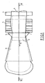
- the device consists schematically of a blowing circuit 1 comprising a blowing orifice 2 of adjustable diameter by which it projects according to arrow A a flow of liquid or gaseous entraining fluid in a support channel 3 which gradually widens in the direction of arrow A.
- the flow A is projected at an angle ⁇ adjustable to the lower part of textile materials gathered in a loop 6 which move along a path 31 defined for this purpose in the internal part of the casing 30 of the machine.
- This movement is controlled by motorized feed wheels 4, 5, 5 ′ mounted in the casing 30 upstream from the orifice 2 relative to the direction of movement B of the materials 6.
- the light textiles pass directly from the wheel 4 into the support channel 3 as shown in dotted lines, while the heavier textiles come to wrap around the wheel 5 before passing between the latter and the wheel 5 ′ which is driven at the same speed.
- These last two wheels are preferably constituted by blade wheels as described in patent FR 82 14 615 so as to prevent any risk of tangling and any friction of the loop 6 on the surface of the wheels such as to cause damage. of the textile material under the effect of the friction thus generated.
- the above-mentioned configuration of the drive wheels is, of course, indicated only by way of example and cannot in any way be considered to be limiting of the invention.
- the fabric 6 leaving the drive wheels 4, 5, 5 ′ arrives in a cham bre bre 7 in which it is stored before being "called” in the support channel 3 under the effect of the flow A projected by the orifice 2 whose section is rectangular in FIG. 1 with the possibility of variants this orifice 2 acts as a nozzle to drive textile materials at high speed by lifting them and at the same time cause them to flourish and flatten out thanks to the special hopper shape of channel 3, so as to greatly facilitate the treatment of these materials.
- the textile materials strike a relaxation plate 32 at the level of which they are compressed before relaxing and falling according to arrow C to the lower part of the casing 30 of the machine, under the effect of their own weight.
- This plate 32 allows, in the absence of liquid in the path 31 of the loop 6, and when the flow A is constituted by a mixture of steam and hot air, to subject the textiles to a treatment called "tumbling" tending to make them non-shrink.
- a pipe 8 associated with an opening 9 allows the introduction into the system, according to arrow D, of various treating products (dyes, degreasers, primers. ..).
- various treating products dye, degreasers, primers. ..
- the pipe 8 can, if necessary, cooperate with additional members not shown in FIG. 2a (pump, heat exchanger, etc.) and the introduction of the products. contractors can be carried out in open circuit or in closed circuit with recycling.
- the treating product comes together at the bottom of the housing 30 in the path 31 to form a treatment bath 33 of the textile material 6 folded in accordion.
- the casing 30 is provided with a valve 34 for discharging saturated air so as to guarantee the safety of the system.
- the wheels 40, 40 ′, 50 three in number which control the movement of the loop 6 of textile material along the path 31 defined for this purpose in the casing 30 ( arrow B), are no longer upstream, but downstream of the orifice 2 of the blowing circuit 1 in the direction B.
- These wheels which also consist of blade wheels driven at corresponding speeds, guarantee a drive optimal tissue 6 without risk of slipping.
- This configuration can be advantageously adopted for dyeing a loop 6 folded in a bath 33 provided at the lower part of the casing 30 of the machine, but of course excludes any possibility of "tumbling" treatment.
- the system can adapt to different geometries from the closed circuit to the open circuit.
- the blowing orifice 2 of the blowing circuit 1 is connected to the discharge of a fluid accelerator 10 shown diagrammatically which is driven by a motor 11 located inside the casing 30 of the machine.
- This accelerator can be of any configuration (pump, fan %) without departing from the scope of the invention.
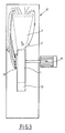
- the fluid accelerator 10 as well as the fluid blowing circuit 1 opening through the blowing orifice in the support channel 3 constitute a closed circuit totally included inside a casing 12 located in the machine housing.
- the fluid leaving along arrow E of the support channel 3 is brought directly into the blowing circuit 1 by a connector 13.
- the blowing circuit 1 as well as the support channel 3 are indeed located inside an envelope 12, but the fluid accelerator 10 and the motor 11 are located outside of this envelope, and connected to circuit 1 by a connector 14.
- this is a system equivalent to that shown in FIG. 3, given that all of the drive fluid leaving the support channel 3 according to arrow E is taken up inside the envelope 12 ′ and brought back into circuit 1.
- FIG. 5 represents a system which is also equivalent to that shown in FIGS. 3 and 4, but which again operates without an envelope, the drive fluid exiting along the arrow E from the support channel 3 is entirely brought back into the system.
- FIG. 6 represents a system of the same type as that shown in FIG. 4, but comprising bypasses such as to allow the addition of complementary products to the flow of drive fluid, or even the implementation of other treatments.
- the support channel 3 thus that the blowing circuit 1 are located in a casing 122, while the fluid accelerator 10 and its drive motor are located outside of the latter and the discharge of the accelerator 10 is connected to the channel l by a complementary pipe 14 so as to allow the blowing of the drive fluid in the support channel 3 according to arrow A.
- an exhaust pipe 15 of the drive fluid to the outside is controlled by a valve 16, as well as a branch pipe 17 comprising a heat exchanger 18 and whose two orifices 19 and 20 are respectively fitted with valves 19 ′ and 20 ′.
- the branch pipe 17 also comprises a first external fluid inlet orifice 21, a second external fluid inlet orifice 22 and an external product inlet orifice 23; these different orifices are respectively fitted with valves 21 ′, 22 ′ and 23 ′.
Landscapes
- Engineering & Computer Science (AREA)
- Textile Engineering (AREA)
- Treatment Of Fiber Materials (AREA)
Applications Claiming Priority (2)
| Application Number | Priority Date | Filing Date | Title |
|---|---|---|---|
| FR8803799A FR2629105B1 (fr) | 1988-03-23 | 1988-03-23 | Dispositif pour le transport et le traitement de matieres textiles |
| FR8803799 | 1988-03-23 |
Publications (1)
| Publication Number | Publication Date |
|---|---|
| EP0334749A1 true EP0334749A1 (de) | 1989-09-27 |
Family
ID=9364563
Family Applications (1)
| Application Number | Title | Priority Date | Filing Date |
|---|---|---|---|
| EP89400791A Withdrawn EP0334749A1 (de) | 1988-03-23 | 1989-03-21 | Vorrichtung zum Halten und Behandeln von textilen Materialien |
Country Status (2)
| Country | Link |
|---|---|
| EP (1) | EP0334749A1 (de) |
| FR (1) | FR2629105B1 (de) |
Cited By (10)
| Publication number | Priority date | Publication date | Assignee | Title |
|---|---|---|---|---|
| EP0512189A1 (de) * | 1991-05-08 | 1992-11-11 | FLAINOX S.r.l. | Vorrichtung zum Färben von strangförmigem Textilgut |
| EP0535287A1 (de) * | 1991-09-21 | 1993-04-07 | Solipat Ag | Verfahren und Vorrichtung zur Griff- und Oberflächenverbesserung von textilen Geweben und Gewirken |
| FR2686102A1 (fr) * | 1992-01-14 | 1993-07-16 | Champagne Teinturerie | Dispositif pour le traitement notamment la teinture de pieces textiles de maniere a garantir une meilleure stabilite dimensionnelle de ces pieces. |
| EP0629732A1 (de) * | 1993-06-10 | 1994-12-21 | Icbt Madinox | Vorrichtung zur Nassbehandlung von endlosem Textilgut |
| FR2713674A1 (fr) * | 1993-12-10 | 1995-06-16 | Icbt Madinox | Dispositif pour le traitement et l'assouplissement d'une étoffe textile sans fin. |
| US5775136A (en) * | 1997-03-31 | 1998-07-07 | Chao-Cheng; Chiang | Spray dyeing apparatus with breadth expansion and vibration-enhanced dyeing operation |
| WO1999057357A1 (fr) * | 1998-05-05 | 1999-11-11 | Alliance Machines Textiles | Machine de traitement au mouille en boyau |
| EP1022371A4 (de) * | 1997-04-29 | 2001-03-28 | Zhaocheng Jiang | Färbemaschine zum auftragen eines behandlungsmittels auf ein gewebe |
| WO2009157883A1 (en) * | 2008-06-23 | 2009-12-30 | Canlar Makina Sanayi Ve Ticaret Limited Sirketi | Fabric dyeing machine having full-scale inner drum which doesn't contain fabric carrying pipe |
| WO2010126455A1 (en) * | 2009-04-30 | 2010-11-04 | Canlar Makina Sanayi Ve Ticaret Limited Sirketi | Invention in garment dyeing machine containing big diameter inner drum and not containing garment conveying pipe |
Citations (9)
| Publication number | Priority date | Publication date | Assignee | Title |
|---|---|---|---|---|
| FR2062685A5 (de) * | 1969-10-27 | 1971-06-25 | Seco Maschinenbau Gmbh | |
| US3599447A (en) * | 1970-01-16 | 1971-08-17 | Komatsu Seiren Co | Apparatus for treating textile materials with a treating liquid |
| FR2178534A5 (de) * | 1972-03-29 | 1973-11-09 | Argelich Termes & Co | |
| FR2206685A7 (de) * | 1972-11-14 | 1974-06-07 | Mcs Officina Meccanica Chiappi | |
| FR2269599A1 (de) * | 1974-05-04 | 1975-11-28 | Thies Alfred | |
| FR2315564A1 (fr) * | 1975-06-26 | 1977-01-21 | Barriquand Freres | Perfectionnements apportes aux appareils de traitement de tissus ou tricots |
| FR2318967A1 (fr) * | 1975-07-21 | 1977-02-18 | Meccaniche L Pozzi Costruzioni | Dispositif pour faire passer de facon controlee, dans des bains de traitement, des produits textiles en forme de cordon |
| FR2450895A1 (fr) * | 1979-03-07 | 1980-10-03 | Thies Kg | Procede et dispositif pour le traitement superficiel de produits textiles sans fin |
| DE3245921A1 (de) * | 1982-12-11 | 1984-06-14 | H. Krantz Gmbh & Co, 5100 Aachen | Nassbehandlungsvorrichtung |
-
1988
- 1988-03-23 FR FR8803799A patent/FR2629105B1/fr not_active Expired - Fee Related
-
1989
- 1989-03-21 EP EP89400791A patent/EP0334749A1/de not_active Withdrawn
Patent Citations (9)
| Publication number | Priority date | Publication date | Assignee | Title |
|---|---|---|---|---|
| FR2062685A5 (de) * | 1969-10-27 | 1971-06-25 | Seco Maschinenbau Gmbh | |
| US3599447A (en) * | 1970-01-16 | 1971-08-17 | Komatsu Seiren Co | Apparatus for treating textile materials with a treating liquid |
| FR2178534A5 (de) * | 1972-03-29 | 1973-11-09 | Argelich Termes & Co | |
| FR2206685A7 (de) * | 1972-11-14 | 1974-06-07 | Mcs Officina Meccanica Chiappi | |
| FR2269599A1 (de) * | 1974-05-04 | 1975-11-28 | Thies Alfred | |
| FR2315564A1 (fr) * | 1975-06-26 | 1977-01-21 | Barriquand Freres | Perfectionnements apportes aux appareils de traitement de tissus ou tricots |
| FR2318967A1 (fr) * | 1975-07-21 | 1977-02-18 | Meccaniche L Pozzi Costruzioni | Dispositif pour faire passer de facon controlee, dans des bains de traitement, des produits textiles en forme de cordon |
| FR2450895A1 (fr) * | 1979-03-07 | 1980-10-03 | Thies Kg | Procede et dispositif pour le traitement superficiel de produits textiles sans fin |
| DE3245921A1 (de) * | 1982-12-11 | 1984-06-14 | H. Krantz Gmbh & Co, 5100 Aachen | Nassbehandlungsvorrichtung |
Cited By (14)
| Publication number | Priority date | Publication date | Assignee | Title |
|---|---|---|---|---|
| EP0512189A1 (de) * | 1991-05-08 | 1992-11-11 | FLAINOX S.r.l. | Vorrichtung zum Färben von strangförmigem Textilgut |
| EP0535287A1 (de) * | 1991-09-21 | 1993-04-07 | Solipat Ag | Verfahren und Vorrichtung zur Griff- und Oberflächenverbesserung von textilen Geweben und Gewirken |
| FR2686102A1 (fr) * | 1992-01-14 | 1993-07-16 | Champagne Teinturerie | Dispositif pour le traitement notamment la teinture de pieces textiles de maniere a garantir une meilleure stabilite dimensionnelle de ces pieces. |
| EP0552100A1 (de) * | 1992-01-14 | 1993-07-21 | Teinturerie De Champagne | Vorrichtung zum Färben von textilen Waren und zum Sichern der Masshaltigkeit derselben |
| EP0629732A1 (de) * | 1993-06-10 | 1994-12-21 | Icbt Madinox | Vorrichtung zur Nassbehandlung von endlosem Textilgut |
| FR2706493A1 (fr) * | 1993-06-10 | 1994-12-23 | Icbt Madinox | Dispositif pour le traitement à l'humide d'une matière textile sans fin au moyen d'un liquide de traitement. |
| FR2713674A1 (fr) * | 1993-12-10 | 1995-06-16 | Icbt Madinox | Dispositif pour le traitement et l'assouplissement d'une étoffe textile sans fin. |
| US5775136A (en) * | 1997-03-31 | 1998-07-07 | Chao-Cheng; Chiang | Spray dyeing apparatus with breadth expansion and vibration-enhanced dyeing operation |
| EP1022371A4 (de) * | 1997-04-29 | 2001-03-28 | Zhaocheng Jiang | Färbemaschine zum auftragen eines behandlungsmittels auf ein gewebe |
| WO1999057357A1 (fr) * | 1998-05-05 | 1999-11-11 | Alliance Machines Textiles | Machine de traitement au mouille en boyau |
| FR2778417A1 (fr) * | 1998-05-05 | 1999-11-12 | Alliance Machines Textiles | Machine de traitement au mouille en boyau |
| US6502432B1 (en) * | 1998-05-05 | 2003-01-07 | Alliance Machines Textiles | Machine for wet rope form treatment |
| WO2009157883A1 (en) * | 2008-06-23 | 2009-12-30 | Canlar Makina Sanayi Ve Ticaret Limited Sirketi | Fabric dyeing machine having full-scale inner drum which doesn't contain fabric carrying pipe |
| WO2010126455A1 (en) * | 2009-04-30 | 2010-11-04 | Canlar Makina Sanayi Ve Ticaret Limited Sirketi | Invention in garment dyeing machine containing big diameter inner drum and not containing garment conveying pipe |
Also Published As
| Publication number | Publication date |
|---|---|
| FR2629105B1 (fr) | 1991-08-16 |
| FR2629105A1 (fr) | 1989-09-29 |
Similar Documents
| Publication | Publication Date | Title |
|---|---|---|
| FR2602525A1 (fr) | Seche-linge a circulation d'air amelioree et procede pour secher des vetements | |
| CH617496A5 (de) | ||
| FR2588290A1 (fr) | Machine de lavage a ultrasons | |
| TWI595135B (zh) | 用於處理繩狀紡織物之裝置 | |
| FR2583863A1 (fr) | Sechoir a rayons infrarouges. | |
| FR2629105A1 (fr) | Dispositif pour le transport et le traitement de matieres textiles | |
| FR2460695A1 (fr) | Procede et dispositif de traitement thermique de produit fluide | |
| EP0349563B1 (de) | Verfahren und vorrichtung zur thermischen behandlung von textilen garnen | |
| FR2544476A1 (fr) | Secheur de produits liquides ou pateux et installation comportant un tel secheur | |
| US3886769A (en) | Width washing plant, particularly for delicate fabrics | |
| JP6442491B2 (ja) | エンドレス生地ストランドの形態のストランド形状織物を処理する装置 | |
| FR2478150A1 (fr) | Machine de traitement thermique de fils textiles | |
| EP1870510B1 (de) | Wäschetrockner, der einen Dampferzeuger umfasst | |
| FR2512083A1 (fr) | Dispositif pour ameliorer le pouvoir de glissement de pieces textiles plates, notamment de pieces de linge, sur des surfaces de repassage | |
| FR2713674A1 (fr) | Dispositif pour le traitement et l'assouplissement d'une étoffe textile sans fin. | |
| EP1870506A1 (de) | Verfahren zur Knittererholung der Wäsche in einem Wäschetrockner | |
| EP0246933A1 (de) | Verfahren und Vorrichtung zum kontinuierlichen Nassbehandeln von textilen Flächengebilden | |
| FR2500921A1 (fr) | Dispositif de commande de l'agent actif dans le traitement thermique de bandes en mouvement | |
| FR2466559A1 (fr) | Perfectionnement aux procedes et aux installations destines au lavage continu et au large, apres impression et/ou decreusage et blanchiment, de tissus ordinaires et a maille | |
| EP0124390B1 (de) | Vorrichtung zur Wärmebehandlung von Teilchen-Material | |
| FR2706493A1 (fr) | Dispositif pour le traitement à l'humide d'une matière textile sans fin au moyen d'un liquide de traitement. | |
| FR2703369A1 (fr) | Dispositif pour le traitement à l'humide d'une matière textile sans fin. | |
| FR2465824A1 (fr) | Machine a laver pour le lavage et le sechage du linge | |
| FR2651805A1 (fr) | Procede et four de sechage de fils textiles en continu. | |
| BE523283A (de) |
Legal Events
| Date | Code | Title | Description |
|---|---|---|---|
| PUAI | Public reference made under article 153(3) epc to a published international application that has entered the european phase |
Free format text: ORIGINAL CODE: 0009012 |
|
| AK | Designated contracting states |
Kind code of ref document: A1 Designated state(s): AT BE CH DE ES FR GB GR IT LI LU NL SE |
|
| 17P | Request for examination filed |
Effective date: 19900308 |
|
| 17Q | First examination report despatched |
Effective date: 19921013 |
|
| STAA | Information on the status of an ep patent application or granted ep patent |
Free format text: STATUS: THE APPLICATION IS DEEMED TO BE WITHDRAWN |
|
| 18D | Application deemed to be withdrawn |
Effective date: 19931102 |