EP0335108A2 - Dispositif de fabrication de produits élastomères en forme de bande - Google Patents
Dispositif de fabrication de produits élastomères en forme de bande Download PDFInfo
- Publication number
- EP0335108A2 EP0335108A2 EP89103226A EP89103226A EP0335108A2 EP 0335108 A2 EP0335108 A2 EP 0335108A2 EP 89103226 A EP89103226 A EP 89103226A EP 89103226 A EP89103226 A EP 89103226A EP 0335108 A2 EP0335108 A2 EP 0335108A2
- Authority
- EP
- European Patent Office
- Prior art keywords
- calender
- roll
- nip
- roller
- calender roll
- Prior art date
- Legal status (The legal status is an assumption and is not a legal conclusion. Google has not performed a legal analysis and makes no representation as to the accuracy of the status listed.)
- Granted
Links
Images

Classifications
-
- B—PERFORMING OPERATIONS; TRANSPORTING
- B29—WORKING OF PLASTICS; WORKING OF SUBSTANCES IN A PLASTIC STATE IN GENERAL
- B29C—SHAPING OR JOINING OF PLASTICS; SHAPING OF MATERIAL IN A PLASTIC STATE, NOT OTHERWISE PROVIDED FOR; AFTER-TREATMENT OF THE SHAPED PRODUCTS, e.g. REPAIRING
- B29C43/00—Compression moulding, i.e. applying external pressure to flow the moulding material; Apparatus therefor
- B29C43/22—Compression moulding, i.e. applying external pressure to flow the moulding material; Apparatus therefor of articles of indefinite length
- B29C43/28—Compression moulding, i.e. applying external pressure to flow the moulding material; Apparatus therefor of articles of indefinite length incorporating preformed parts or layers, e.g. compression moulding around inserts or for coating articles
-
- B—PERFORMING OPERATIONS; TRANSPORTING
- B29—WORKING OF PLASTICS; WORKING OF SUBSTANCES IN A PLASTIC STATE IN GENERAL
- B29C—SHAPING OR JOINING OF PLASTICS; SHAPING OF MATERIAL IN A PLASTIC STATE, NOT OTHERWISE PROVIDED FOR; AFTER-TREATMENT OF THE SHAPED PRODUCTS, e.g. REPAIRING
- B29C43/00—Compression moulding, i.e. applying external pressure to flow the moulding material; Apparatus therefor
- B29C43/22—Compression moulding, i.e. applying external pressure to flow the moulding material; Apparatus therefor of articles of indefinite length
- B29C43/24—Calendering
-
- B—PERFORMING OPERATIONS; TRANSPORTING
- B29—WORKING OF PLASTICS; WORKING OF SUBSTANCES IN A PLASTIC STATE IN GENERAL
- B29D—PRODUCING PARTICULAR ARTICLES FROM PLASTICS OR FROM SUBSTANCES IN A PLASTIC STATE
- B29D29/00—Producing belts or bands
- B29D29/06—Conveyor belts
-
- B—PERFORMING OPERATIONS; TRANSPORTING
- B29—WORKING OF PLASTICS; WORKING OF SUBSTANCES IN A PLASTIC STATE IN GENERAL
- B29C—SHAPING OR JOINING OF PLASTICS; SHAPING OF MATERIAL IN A PLASTIC STATE, NOT OTHERWISE PROVIDED FOR; AFTER-TREATMENT OF THE SHAPED PRODUCTS, e.g. REPAIRING
- B29C48/00—Extrusion moulding, i.e. expressing the moulding material through a die or nozzle which imparts the desired form; Apparatus therefor
- B29C48/03—Extrusion moulding, i.e. expressing the moulding material through a die or nozzle which imparts the desired form; Apparatus therefor characterised by the shape of the extruded material at extrusion
- B29C48/07—Flat, e.g. panels
-
- B—PERFORMING OPERATIONS; TRANSPORTING
- B29—WORKING OF PLASTICS; WORKING OF SUBSTANCES IN A PLASTIC STATE IN GENERAL
- B29K—INDEXING SCHEME ASSOCIATED WITH SUBCLASSES B29B, B29C OR B29D, RELATING TO MOULDING MATERIALS OR TO MATERIALS FOR MOULDS, REINFORCEMENTS, FILLERS OR PREFORMED PARTS, e.g. INSERTS
- B29K2021/00—Use of unspecified rubbers as moulding material
Definitions
- the invention relates to a device for producing web-shaped rubber products, in particular conveyor belts, consisting essentially of an unwinding station for feeding the material to be processed, a calendering station for calendering the material being fed, and a receiving station for receiving the calendered products.
- Such a device is used for the continuous production of long, web-shaped rubber products, in particular conveyor belts, which are provided with a reinforcement insert which is particularly resilient in the longitudinal direction.
- reinforcement inserts of this type must be surrounded with rubber on all sides.
- the reinforcing insert is introduced into a calender from an unwinding station, a rubber web, which is stored on separate unwinding stations, being guided from above and below against the reinforcing fabric insert and connected to one another in the calender.
- Plate webs of this type are usually produced with the aid of injection molding machines which have a wide injection head with which a profile corresponding to the desired article profile can be preformed. Due to the friction on the edges of the mouthpiece, however, the material particles are braked differently and tensions arise within the profile. From US 3,871,810 it is known to arrange a roller for recalibration after the mouthpiece. The plates produced are semi-finished products that have to be further processed in another plant.
- the object of the present invention is to provide a device of the type described in the introduction with which all of the operations described above can be carried out.
- the calender station comprises at least five calender rolls.
- the fifth calender roll has no function.
- This plate produced in this way can be doubled with the same system by inserting it into the second nip and another plate, which has been prefabricated in the same way, into the fourth nip and guiding both plates against one another in the third nip and connecting them to one another.
- the first calender roll can have no function or can be used to shape the upper rubber plate in the manner described above.
- the fabric inserts are rubberized on both sides for better adhesion.
- This operation can also be carried out in the system according to the invention.
- the fabric insert which is held in known storage stations, is drawn into the third nip, while at the same time an upper rubber plate fed through the second nip and from below one through the fourth nip fed second rubber sheet against the fabric insert and all three layers are connected.
- the first roller is out of function.
- the thicker support strip by means of an extruder with a wide die head into a first nip between a first calender roll and a second calender roll of at least five calender rolls having the calender station, recalibrated in a second nip between a second calender roll and a third calender roll and a third nip between a third calender roll and a fourth calender roll, the prefabricated carcass is passed under a fifth calender roll into the fourth nip between the fourth calender roll and fifth calender roll is fed and the carcass is embedded on the running side and on the edges in likewise lined, plasticized rubber, and in the third nip of third calender roll and fourth K
- the carcass which is encased on three sides with rubber, is covered with a supporting strip on the support side, which was fed into the first
- the conveyor belt produced in this way runs into a receiving station downstream of the third nip, for example a cooling section and a changing table, and can be removed from there from the side.
- the device 1 shown in FIG. 1 essentially consists of an unwinding station 2, on which stock material wound on winding trestles 9 is stored, a calender station 10 and a winding station 3, in which the preliminary or finished product coming from the calender station is also on winding trestles 9 is wound up.
- the calender station 10 is preceded by a storage station 4, with which the incoming material is stored and kept under tension via tension retention 5.
- the semi-finished or finished product coming from the calender station 10 can enter a cooling section 6 and / or a compensating device 7 and / or be fed to a changing table 8 or a doubling unit 38.
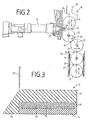
- the calender station 10 shown in FIG. 2 essentially consists of a first calender roll 11 and a second calender roll 12 arranged vertically below it.
- the first calender roll 11 is adjustable in height and the second calender roll 12 is arranged fixed in a roll stand 16. Between the first calender roll 11 and the second calender roll 12 there is a first roll gap 17, the height of which can be varied by the height adjustment of the first calender roll 11.
- a second vertical roller group 25 Parallel to the first vertical roller group 24, consisting of the first calender roller 11 and the second calender roller 12, is a second vertical roller group 25, which comprises a third calender roller 13, a fourth calender roller 14 and a fifth calender roller 15.
- the third calender roll 13 is the uppermost of the second roll group 25 and is lowered from the horizontal by a predetermined angle 26 with respect to the second calender roll 12.
- the angle 26, by which the third calender roll 13 is arranged obliquely below the second calender roll 12, is approximately 10 to 45 degrees, preferably 30 degrees.
- the third calender roll 13 is horizontally movable so that the second nip 18 between it and the second calender roll 12 can be varied, while at the same time the third nip 19 between the third calender roll 13 and the fixed fourth calender roll 14 remains essentially constant.
- a fifth calender roll 15 is arranged vertically below the fourth calender roll 14. This pair of rollers 14 and 15 forms a fourth nip 20 between them.
- the fifth calender roller 15 is in turn vertically adjustable in height, so that the fourth nip 20 can also be varied.
- the fifth calender roll 15 is at a predetermined angle arranged obliquely below the fourth calender roll 14 and in the vertical parallel to this.
- the fourth calender roll 14 and the fifth calender roll 15 are mounted in a common roll block 27.
- the fourth calender roll 14 is fixed in this roll block 27 and the height of the fifth calender roll 15 is variable; together, these two rollers 14 and 15 are height-adjustable with the roller block 27, so that the height of the third roller nip 19 between the third calender roller 13 and the fourth calender roller 14 is also variable.
- the first pair of rollers 11 and 12 is assigned an extruder 21 in which rubber material can be plasticized and pre-profiled by means of a wide die head 22 with a corresponding mouthpiece 23 and fed to the first nip 17.
- the extruder 21 lies high relative to the second roller group 25 and can be moved away from the first roller gap 17 to form pre-shaped plate profiles.
- the prefabricated plate profiles 29 can be used to rubberize a fabric web 30 in the third nip 19 on both sides.
- a first plate profile 29 is fed into the second working gap 18 and a second plate profile 29 into the fourth working gap 20 against the general working direction 20 (arrow), in the working direction 28 introduced into the third working gap 19 and brought together there with the fabric web 30.
- Such a conveyor belt 31 consists essentially of a multi-layer fabric belt 32, which is surrounded on its top with a thicker rubber 34 and on its underside with a thinner rubber 35.
- the multi-layer fabric tape 32 consists of a multiplicity of individual fabric webs 30, which are individually manufactured in the manner described above, placed one above the other in a separate installation and connected to one another.
- a lateral protrusion 33 is produced in the covering of the carcass or the fabric band 32 described above, which is trimmed with the lateral disc knives 37 arranged downstream of the roller gap 19.
- the rubber edges 36 amount to approximately 0.5 to 1.2, preferably 0.7 x the thickness of the entire conveyor belt 31.
- the laterally cut-off projections 33 can be fed into the lower, the fourth nip 20 and thus used again.
- the fourth nip 20 is set to a gap dimension which corresponds to the addition of the carcass thickness + the running rubber coating.
- edges 36 are set up at a distance of approximately 100 mm from the edges of the fabric layers 30, not shown.
- the fabric layer 30 is embedded on the run side and at its edges with a width of up to 100 mm.
Landscapes
- Engineering & Computer Science (AREA)
- Mechanical Engineering (AREA)
- Casting Or Compression Moulding Of Plastics Or The Like (AREA)
- Tyre Moulding (AREA)
- Processing And Handling Of Plastics And Other Materials For Molding In General (AREA)
- Heating, Cooling, Or Curing Plastics Or The Like In General (AREA)
Priority Applications (1)
| Application Number | Priority Date | Filing Date | Title |
|---|---|---|---|
| AT8989103226T ATE104903T1 (de) | 1988-03-30 | 1989-02-24 | Einrichtung zur herstellung von bahnfoermigen kautschukprodukten. |
Applications Claiming Priority (2)
| Application Number | Priority Date | Filing Date | Title |
|---|---|---|---|
| DE3810810A DE3810810A1 (de) | 1988-03-30 | 1988-03-30 | Einrichtung zur herstellung von bahnfoermigen kautschukprodukten |
| DE3810810 | 1988-03-30 |
Publications (3)
| Publication Number | Publication Date |
|---|---|
| EP0335108A2 true EP0335108A2 (fr) | 1989-10-04 |
| EP0335108A3 EP0335108A3 (fr) | 1991-09-25 |
| EP0335108B1 EP0335108B1 (fr) | 1994-04-27 |
Family
ID=6351071
Family Applications (1)
| Application Number | Title | Priority Date | Filing Date |
|---|---|---|---|
| EP89103226A Expired - Lifetime EP0335108B1 (fr) | 1988-03-30 | 1989-02-24 | Dispositif de fabrication de produits élastomères en forme de bande |
Country Status (3)
| Country | Link |
|---|---|
| EP (1) | EP0335108B1 (fr) |
| AT (1) | ATE104903T1 (fr) |
| DE (2) | DE3810810A1 (fr) |
Cited By (5)
| Publication number | Priority date | Publication date | Assignee | Title |
|---|---|---|---|---|
| CN102174297A (zh) * | 2010-12-21 | 2011-09-07 | 周炳光 | 固体硅胶带生产设备 |
| CN102658637A (zh) * | 2012-05-17 | 2012-09-12 | 贵州省复合改性聚合物材料工程技术研究中心 | 提高牵引机工作效率及牵引质量的方法及装置 |
| CN102990948A (zh) * | 2012-11-27 | 2013-03-27 | 常州悦诚新材料有限公司 | 连续玻纤布热塑性塑料板材的生产设备 |
| US11167465B2 (en) | 2017-09-26 | 2021-11-09 | Davis-Standard, Llc | Casting apparatus for manufacturing polymer film |
| CN118560078A (zh) * | 2024-06-11 | 2024-08-30 | 江苏凯嘉橡胶科技股份有限公司 | 一种橡胶输送带生产用胶料挤出装置 |
Families Citing this family (2)
| Publication number | Priority date | Publication date | Assignee | Title |
|---|---|---|---|---|
| DE4220839C1 (fr) * | 1992-06-25 | 1993-09-09 | Roehm Gmbh, 64293 Darmstadt, De | |
| DE10250780A1 (de) * | 2002-10-30 | 2004-05-19 | Henkel Kgaa | Mehrschicht Laminate zum Versteifen |
Family Cites Families (24)
| Publication number | Priority date | Publication date | Assignee | Title |
|---|---|---|---|---|
| DE707038C (de) * | 1938-04-29 | 1941-06-11 | Willy Stelkens | Schlitzpresse zum ununterbrochenen Verarbeiten plastischer Massen zu Filmen, Folien o. dgl. |
| DE748322C (de) * | 1942-08-06 | 1944-11-01 | Verfahren zur Herstellung von Foerderbaendern | |
| BE494719A (fr) * | 1949-03-23 | 1900-01-01 | ||
| GB1013639A (en) * | 1963-05-28 | 1965-12-15 | Continental Gummi Werke Ag | Method and apparatus for stretching wires or cables |
| NL6413790A (fr) * | 1964-11-27 | 1966-05-31 | ||
| US3358321A (en) * | 1966-04-12 | 1967-12-19 | Adamson United Company | Calender with extra roll |
| FR1518200A (fr) * | 1967-04-07 | 1968-03-22 | Adamson United Company | Dispositif de calandrage perfectionné |
| GB1217548A (en) * | 1967-11-30 | 1970-12-31 | Schloemann Ag | Improvements in calendars, particularly in drawing calendars for the production of webs of film |
| US3547682A (en) * | 1968-03-15 | 1970-12-15 | Hercules Inc | Composite polyolefin extrusion coating of substrates |
| GB1253886A (en) * | 1969-02-07 | 1971-11-17 | David Bridge & Company Ltd | Improvements in or relating to the production of sheets of material |
| DE1951983A1 (de) * | 1969-10-15 | 1971-04-22 | Hermann Berstorff Maschb Gmbh | Einrichtung zur Herstellung von Foerderbaendern |
| DE2159684A1 (de) * | 1971-12-01 | 1973-06-07 | Berstorff Gmbh Masch Hermann | Verfahren und einrichtung zum herstellen von foerderbaendern |
| JPS5438145B2 (fr) * | 1972-03-31 | 1979-11-19 | ||
| US3871810A (en) * | 1972-11-20 | 1975-03-18 | Uniroyal Inc | Extruder and roller-die combination |
| SE389055B (sv) * | 1973-12-05 | 1976-10-25 | Akerlund & Rausing Ab | Forfarande for forhindrande av spill vid igangsettning, avstengning resp. tillfelliga avbrott vid extrudering av plastmaterial |
| DE2460873A1 (de) * | 1974-12-21 | 1976-06-24 | Berstorff Gmbh Masch Hermann | Kunststoffolienherstellungsanlage mit einem mehrwalzenkalander |
| DE2528219C3 (de) * | 1975-06-25 | 1979-04-19 | Continental Gummi-Werke Ag, 3000 Hannover | Einrichtung zum Herstellen von Fördergurten |
| DE2601265C3 (de) * | 1976-01-15 | 1979-08-02 | Continental Gummi-Werke Ag, 3000 Hannover | Kalander mit drei Walzen in L-Anordnung |
| DE2639512C3 (de) * | 1976-09-02 | 1984-07-19 | Reifenhäuser KG, 5210 Troisdorf | Vorrichtung zum Herstellen eines dicken Tafelstranges aus thermoplastischem Kunststoff |
| DE2721095B2 (de) * | 1977-05-11 | 1980-02-28 | Reifenhaeuser Kg, 5210 Troisdorf | Anlage zum Strangpressen von Kunststoffgegenständen |
| DE2845650B2 (de) * | 1978-10-20 | 1981-02-19 | Mannesmann Demag Kunststofftechnik Zweigniederlassung Der Mannesmann Demag Ag, 8500 Nuernberg | Verfahren und Vorrichtung zur Herstellung von Kunststoff-Flach- oder Blasfolien |
| JPS55166234A (en) * | 1979-06-12 | 1980-12-25 | Kobe Steel Ltd | Noncontact type extruding machine with roller die |
| FR2462987A1 (fr) * | 1979-08-02 | 1981-02-20 | Celanese Corp | Procede de preparation d'un materiau en feuille thermoplastique continu, extrude et charge et plus particulierement d'un polyalcoylene terephtalate, materiau en feuille obtenu, dispositif et plaque perforee a utiliser pour son extrusion |
| DE2937204C2 (de) * | 1979-09-14 | 1982-09-02 | Werner & Pfleiderer, 7000 Stuttgart | Extrudermaschine mit Breitspritzkopf und zugeordnetem Kalander |
-
1988
- 1988-03-30 DE DE3810810A patent/DE3810810A1/de not_active Withdrawn
-
1989
- 1989-02-24 DE DE58907541T patent/DE58907541D1/de not_active Expired - Fee Related
- 1989-02-24 AT AT8989103226T patent/ATE104903T1/de not_active IP Right Cessation
- 1989-02-24 EP EP89103226A patent/EP0335108B1/fr not_active Expired - Lifetime
Cited By (8)
| Publication number | Priority date | Publication date | Assignee | Title |
|---|---|---|---|---|
| CN102174297A (zh) * | 2010-12-21 | 2011-09-07 | 周炳光 | 固体硅胶带生产设备 |
| CN102174297B (zh) * | 2010-12-21 | 2013-10-16 | 周炳光 | 固体硅胶带生产设备 |
| CN102658637A (zh) * | 2012-05-17 | 2012-09-12 | 贵州省复合改性聚合物材料工程技术研究中心 | 提高牵引机工作效率及牵引质量的方法及装置 |
| CN102990948A (zh) * | 2012-11-27 | 2013-03-27 | 常州悦诚新材料有限公司 | 连续玻纤布热塑性塑料板材的生产设备 |
| CN102990948B (zh) * | 2012-11-27 | 2015-03-11 | 常州悦诚新材料有限公司 | 连续玻纤布热塑性塑料板材的生产设备 |
| US11167465B2 (en) | 2017-09-26 | 2021-11-09 | Davis-Standard, Llc | Casting apparatus for manufacturing polymer film |
| US11173644B2 (en) | 2017-09-26 | 2021-11-16 | Davis-Standard, Llc | Casting apparatus for manufacturing polymer film |
| CN118560078A (zh) * | 2024-06-11 | 2024-08-30 | 江苏凯嘉橡胶科技股份有限公司 | 一种橡胶输送带生产用胶料挤出装置 |
Also Published As
| Publication number | Publication date |
|---|---|
| DE3810810A1 (de) | 1989-10-12 |
| EP0335108B1 (fr) | 1994-04-27 |
| DE58907541D1 (de) | 1994-06-01 |
| ATE104903T1 (de) | 1994-05-15 |
| EP0335108A3 (fr) | 1991-09-25 |
Similar Documents
| Publication | Publication Date | Title |
|---|---|---|
| DE4034144C2 (de) | Strangpreßwalz-Vorrichtung und Verfahren zu deren Betrieb | |
| DE69120010T2 (de) | Verfahren und Vorrichtung zum Herstellen einer gummierten, mit Stahlfäden verstärkten Bahn | |
| EP0461488A2 (fr) | Procédé pour fabriquer des feuilles ou des plaques massives lissées extrudées en matière thermoplastique | |
| DE1942784B1 (de) | Verfahren zum Ummanteln von Bandkabeln | |
| EP0314900A2 (fr) | Procédé et système de calandrage pour fabriquer des bandes profilées pour pneus composées de plusieurs de caoutchouc | |
| DE69827966T2 (de) | Verfahren zur herstellung einer querfaserbahn | |
| DE2431385C3 (de) | Verfahren und Vorrichtung zur Herstellung von verstreckten Flachfolienbahnen aus thermoplastischen Kunststoffen | |
| DE69110396T2 (de) | Vorrichtung und Verfahren zum Herstellen von grünen Reifen. | |
| DE2819221A1 (de) | Verfahren zum kontinuierlichen giessen einer reihe thermoplastischer sperrglieder eines reissverschlusses auf die laengskante eines traegers sowie vorrichtung zur durchfuehrung des verfahrens | |
| EP0335108B1 (fr) | Dispositif de fabrication de produits élastomères en forme de bande | |
| EP0281882A2 (fr) | Procédé et dispositifs pour la fabrication de panneaux multicouches | |
| EP0335152A2 (fr) | Procédé de fabrication de bande de convoyage et dispositif pour la mise en oeuvre du procédé | |
| DE2848295C2 (de) | Kalander zur Herstellung von thermoplastischer Folien | |
| EP3432719B1 (fr) | Méthode pour mésurer la distribution de masse | |
| DE602004008368T2 (de) | Kaschiermaschine | |
| DE3206164C2 (de) | Vorrichtung zur Herstellung von Mehrschicht-Platten | |
| DE10258353B4 (de) | Kalanderanlage zur Herstellung von Stahlseilkarkassenbahnen | |
| DE2225204A1 (de) | Vorrichtung zur herstellung von kaschierten hartschaumplatten auf der basis von polyurethan | |
| EP0681981B1 (fr) | Peigne de répartition | |
| DE69124984T2 (de) | Verfahren und Wickelvorrichtung für eine Reifenaufbaumaschine | |
| DE1929350C3 (de) | Kalander für die Herstellung von glatten Bahnen oder Folien aus thermoplastischem Material | |
| DE68901851T2 (de) | Verfahren und vorrichtung zum beschichten von parallel liegenden faeden mit kautschuk und so hergestellte matte. | |
| DE3490776C2 (de) | Verfahren und Vorrichtung zur Membranherstellung | |
| DE602004013164T2 (de) | Aufwickelvorrichtung für walzhalbzeuge | |
| DE19900357C1 (de) | Verfahren zum Ausgleichen von Temperaturdifferenzen in Kunststoffplatten |
Legal Events
| Date | Code | Title | Description |
|---|---|---|---|
| PUAI | Public reference made under article 153(3) epc to a published international application that has entered the european phase |
Free format text: ORIGINAL CODE: 0009012 |
|
| AK | Designated contracting states |
Kind code of ref document: A2 Designated state(s): AT DE FR GB IT NL SE |
|
| PUAL | Search report despatched |
Free format text: ORIGINAL CODE: 0009013 |
|
| AK | Designated contracting states |
Kind code of ref document: A3 Designated state(s): AT DE FR GB IT NL SE |
|
| 17P | Request for examination filed |
Effective date: 19911106 |
|
| 17Q | First examination report despatched |
Effective date: 19920929 |
|
| GRAA | (expected) grant |
Free format text: ORIGINAL CODE: 0009210 |
|
| AK | Designated contracting states |
Kind code of ref document: B1 Designated state(s): AT DE FR GB IT NL SE |
|
| PG25 | Lapsed in a contracting state [announced via postgrant information from national office to epo] |
Ref country code: IT Free format text: LAPSE BECAUSE OF FAILURE TO SUBMIT A TRANSLATION OF THE DESCRIPTION OR TO PAY THE FEE WITHIN THE PRESCRIBED TIME-LIMIT;WARNING: LAPSES OF ITALIAN PATENTS WITH EFFECTIVE DATE BEFORE 2007 MAY HAVE OCCURRED AT ANY TIME BEFORE 2007. THE CORRECT EFFECTIVE DATE MAY BE DIFFERENT FROM THE ONE RECORDED. Effective date: 19940427 Ref country code: SE Free format text: THE PATENT HAS BEEN ANNULLED BY A DECISION OF A NATIONAL AUTHORITY Effective date: 19940427 Ref country code: GB Effective date: 19940427 Ref country code: NL Effective date: 19940427 Ref country code: FR Effective date: 19940427 |
|
| REF | Corresponds to: |
Ref document number: 104903 Country of ref document: AT Date of ref document: 19940515 Kind code of ref document: T |
|
| REF | Corresponds to: |
Ref document number: 58907541 Country of ref document: DE Date of ref document: 19940601 |
|
| EN | Fr: translation not filed | ||
| NLV1 | Nl: lapsed or annulled due to failure to fulfill the requirements of art. 29p and 29m of the patents act | ||
| GBV | Gb: ep patent (uk) treated as always having been void in accordance with gb section 77(7)/1977 [no translation filed] |
Effective date: 19940427 |
|
| PG25 | Lapsed in a contracting state [announced via postgrant information from national office to epo] |
Ref country code: AT Effective date: 19950224 |
|
| PLBE | No opposition filed within time limit |
Free format text: ORIGINAL CODE: 0009261 |
|
| STAA | Information on the status of an ep patent application or granted ep patent |
Free format text: STATUS: NO OPPOSITION FILED WITHIN TIME LIMIT |
|
| 26N | No opposition filed | ||
| PGFP | Annual fee paid to national office [announced via postgrant information from national office to epo] |
Ref country code: DE Payment date: 19960426 Year of fee payment: 8 |
|
| PG25 | Lapsed in a contracting state [announced via postgrant information from national office to epo] |
Ref country code: DE Effective date: 19971101 |