EP0681981B1 - Peigne de répartition - Google Patents
Peigne de répartition Download PDFInfo
- Publication number
- EP0681981B1 EP0681981B1 EP95890068A EP95890068A EP0681981B1 EP 0681981 B1 EP0681981 B1 EP 0681981B1 EP 95890068 A EP95890068 A EP 95890068A EP 95890068 A EP95890068 A EP 95890068A EP 0681981 B1 EP0681981 B1 EP 0681981B1
- Authority
- EP
- European Patent Office
- Prior art keywords
- dividing
- comb
- steel cord
- lamellae
- dividing comb
- Prior art date
- Legal status (The legal status is an assumption and is not a legal conclusion. Google has not performed a legal analysis and makes no representation as to the accuracy of the status listed.)
- Expired - Lifetime
Links
Images
Classifications
-
- B—PERFORMING OPERATIONS; TRANSPORTING
- B65—CONVEYING; PACKING; STORING; HANDLING THIN OR FILAMENTARY MATERIAL
- B65H—HANDLING THIN OR FILAMENTARY MATERIAL, e.g. SHEETS, WEBS, CABLES
- B65H57/00—Guides for filamentary materials; Supports therefor
- B65H57/16—Guides for filamentary materials; Supports therefor formed to maintain a plurality of filaments in spaced relation
Definitions
- the present invention relates to a dividing comb with a multiplicity of mutually spaced-apart slats for feeding a steel cord family from steel threads or steel cords running in parallel and at least essentially in one plane to a steel cord calender, and a device for a dividing comb according to the invention.
- steel cord calenders are used to produce rubberized steel cord sheets, which are subsequently cut into corresponding single sheets and are used, for example, as belt layers in the manufacture of vehicle tires.
- the steel cord thread sheet is usually supplied by a gate equipped with a large number of steel cord spools, the individual cords being manually threaded through the spaces between the individual lamellae of the dividing comb.
- a dividing comb according to the prior art has a plurality of equally spaced lamellae, the mutual spacing of which corresponds to the desired thread division (number of steel cords per 10 cm).
- the steel cord thread sheet then runs over a dividing roller which has a multiplicity of guide grooves, the mutual spacing of which corresponds to the spacing between the steel cords which is predetermined by the thread division on the dividing comb.
- the steel cord thread sheet runs over this dividing roller into the press nip between two calender rollers.
- a number of time-consuming steps are required if the thread pitch of the rubber-coated steel cord sheets produced is to be changed.
- the calender is shut down, the steel cords are cut off and remnants of the mixture are removed from the calender.
- the dividing comb that is no longer suitable is removed.
- the creel is routed to a set-up station, where the individual steel cords are threaded into a dividing comb with the desired thread division.
- the creel is brought back into its calender position, the new dividing comb is mounted and finally the matching dividing roller is fixed after removing the other dividing roller.
- the mixture must be preheated and fed into the nips.
- the invention has now set itself the task of designing a division comb for a steel cord thread set so that the described time-consuming process is largely avoided.
- the dividing comb has lamellae arranged in a fan-like manner, the lamellae being conical in cross section and a larger lamella cross section corresponding to the setting of a lower thread pitch.
- the arrangement of the lamellae is preferably such that the gap between all lamellae on the dividing comb has a constant width. This design variant ensures that the fin spacing is matched to the steel cord diameter in every possible thread division.
- the handling of the dividing comb according to the invention for changing the thread pitch is easily possible if the dividing comb on the comb carrier is at least substantially displaceable in a direction normal to the direction of travel of the steel cord thread sheet and is arranged to be fixable in different positions.
- the invention further relates to a device arranged upstream of a steel cord calender for a dividing comb designed according to the invention.
- this device has a pair of guide rollers or the like, between which the steel cord thread family runs.
- the guide rollers help to ensure that the steel cords are guided parallel and essentially in one plane through the dividing comb.
- the guide rollers are advantageously displaceable on the device and can be fixed in different positions.
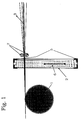
- FIG. 1 shows schematically and in side view the basic arrangement of a dividing comb with associated dividing roller
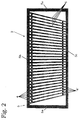
- FIG. 2 schematically shows a variant of a dividing comb according to the present invention in plan view.
- the steel cord calender itself is not the subject of the present invention and is therefore not shown in the drawing figures.
- the calender can be, for example, a two-roll calender (cold process) or a four-roll calender (hot process).
- Fig. 1 shows the dividing roller 1 arranged in front of the press nip of the calender, a dividing comb 2 positioned in front of the dividing roller 1 and a steel cord family 3, the individual steel cords of which are threaded through the dividing comb 2 and run over the dividing roller 1 into the press nip between two calender rollers.
- the dividing roller 1 has in a known and therefore not shown manner a plurality of circumferential guide grooves for receiving or guiding the individual steel cords.
- the mutual spacing of the individual guide grooves corresponds to the thread spacing set on the dividing comb 2, which is usually called thread division.
- a thread pitch of 80 means that 80 threads of steel cord per 10 cm are present both on the dividing comb 2 and on the dividing roller 1.
- the family of threads is supplied in a manner known per se from a gate equipped with a large number of bobbins, which is likewise not part of the present invention.
- the dividing comb 2 shows an exemplary embodiment of a dividing comb 2 designed according to the present invention.
- the dividing comb 2 consists of a solid, metallic frame 5, which is closed on all sides, and of a multiplicity of likewise metallic slats 6.
- the frame 5, which is designed in a rectangular shape from two side parts 5a and one upper and lower part 5b, 5c, the slats 6 running or being arranged between the upper and lower parts 5b, 5c.
- a dividing comb usually has between 800 and 1,200 lamellae, in the drawing figures 2 and 3 a much smaller number of lamellae is shown for the sake of simplicity.
- the slats 6 have a conical cross section, in such a way that their cross section starting from the upper frame part 5b to the lower frame part 5c becomes too small.
- the mutual arrangement of the slats 6 between the frame parts 5b, 5c takes place in a fan-like manner and in such a way that there is an equal distance between the mutually adjacent slats 6, which is slightly larger than the diameter of the threaded steel cords 4.
- the direction of displacement of the division comb 2 is symbolized by the double arrow.
- the displacement and also the respective position fixing of the dividing comb 2 takes place by means of suitable mechanisms, which are provided, for example, on the comb carrier (not shown).
- guide rollers 7 or the like can be positioned just above and just below the steel cord thread family in order to additionally fix the selected steel cord spacing or the selected thread pitch.
- the guide rollers 7 can be arranged on the comb carrier or a separate supporting part in a suitable manner.
- a variation in the thread division can take place, which is in the range of approximately 10 to 15 threads per 10 cm.
- a change from a thread division from 95 to a thread division from 80, or from a thread division from 40 to a thread division from 50 can take place.
- the advantages of the present invention are in particular an enormous saving in time, but also in the fact that the total number of division combs available can be considerably reduced.
Landscapes
- Moulding By Coating Moulds (AREA)
- Liquid Developers In Electrophotography (AREA)
- Inorganic Insulating Materials (AREA)
- Casting Or Compression Moulding Of Plastics Or The Like (AREA)
- Tyre Moulding (AREA)
- Reduction Or Emphasis Of Bandwidth Of Signals (AREA)
- Dry Formation Of Fiberboard And The Like (AREA)
Claims (5)
- Peigne de répartition muni d'un grand nombre de lamelles mutuellement espacées, en vue de délivrer, à une calandre à câblés d'acier, une nappe de câblés d'acier constituée par des fils d'acier ou par des câblés d'acier à répartition déterminée, s'étendant parallèlement et au moins pour l'essentiel dans un plan, caractérisé par le fait qu'il présente des lamelles (6) agencées à la manière d'un éventail, les lamelles (6) étant de configuration conique en coupe transversale, et une plus forte section transversale desdites lamelles correspondant au réglage d'une plus faible répartition des fils.
- Peigne de répartition selon la revendication 1, caractérisé par le fait que l'interstice entre les lamelles (6) présente une largeur constante.
- Peigne de répartition selon la revendication 1 ou 2, caractérisé par le fait qu'il est agencé, sur le porte-peigne, avec faculté de coulissement au moins pour l'essentiel dans une direction perpendiculaire à la direction du défilement de la nappe de câblés d'acier, et avec faculté de consignation à demeure dans différentes positions.
- Dispositif destiné à un peigne de répartition selon l'une des revendications 1 à 3, caractérisé par le fait qu'il comprend une paire de rouleaux de guidage (7) ou éléments similaires qui sont disposés avant le peigne de répartition (2), et entre lesquels s'étend la nappe de câblés d'acier.
- Dispositif selon la revendication 4, caractérisé par le fait que les rouleaux de guidage (7) sont agencés avec faculté de coulissement et de consignation à demeure dans différentes positions.
Applications Claiming Priority (2)
| Application Number | Priority Date | Filing Date | Title |
|---|---|---|---|
| AT771/94 | 1994-04-14 | ||
| AT0077194A AT402204B (de) | 1994-04-14 | 1994-04-14 | Teilungskamm |
Publications (2)
| Publication Number | Publication Date |
|---|---|
| EP0681981A1 EP0681981A1 (fr) | 1995-11-15 |
| EP0681981B1 true EP0681981B1 (fr) | 1997-05-02 |
Family
ID=3499325
Family Applications (1)
| Application Number | Title | Priority Date | Filing Date |
|---|---|---|---|
| EP95890068A Expired - Lifetime EP0681981B1 (fr) | 1994-04-14 | 1995-03-30 | Peigne de répartition |
Country Status (3)
| Country | Link |
|---|---|
| EP (1) | EP0681981B1 (fr) |
| AT (2) | AT402204B (fr) |
| DE (1) | DE59500204D1 (fr) |
Families Citing this family (5)
| Publication number | Priority date | Publication date | Assignee | Title |
|---|---|---|---|---|
| DE602006004406D1 (de) | 2005-07-29 | 2009-02-05 | Hexcel Reinforcements | Platzierungsverfahren eines Drahtelementes, das für die Bildung von ring- oder ellipsoidartigen Vorformlingen geeignet ist |
| FR2889103B1 (fr) * | 2005-07-29 | 2009-08-28 | Hexcel Reinforcements Soc Par | Procede et dispositif de depose simultanee d'une serie d'elements filaires avec variation controlee de la distance entre les fibres moyennes des elements filaires |
| CN101559651B (zh) * | 2009-05-22 | 2012-09-05 | 无锡宝通带业股份有限公司 | 钢丝绳o形移动分梳器 |
| CN104384889B (zh) * | 2014-08-28 | 2016-10-05 | 中联重科股份有限公司 | 油缸与钢丝绳的装配装置 |
| CN113968518B (zh) * | 2021-10-25 | 2022-08-09 | 江苏佩捷纺织智能科技有限公司 | 一种织机单幅往复导丝工艺及其设备 |
Family Cites Families (6)
| Publication number | Priority date | Publication date | Assignee | Title |
|---|---|---|---|---|
| US1289015A (en) * | 1917-03-15 | 1918-12-24 | Friederick Suter | Reed for warping-machines. |
| CH78081A (de) * | 1918-01-22 | 1918-10-16 | E Sommerhalder | Blatt, insbesondere für die Herstellung des Zettels von Bändern |
| CH344806A (de) * | 1955-04-06 | 1960-02-29 | Glanzstoff Ag | Vorrichtung zum Führen der Einzelfäden von Fadenscharen |
| NL6606476A (fr) * | 1966-05-12 | 1967-11-13 | ||
| US3980251A (en) * | 1973-07-23 | 1976-09-14 | Wyatt Dickie R | Apparatus for changing thread spacing |
| DE3527964C1 (de) * | 1985-08-03 | 1987-04-16 | Boehler Ag | Verfahren und Vorrichtung zur Herstellung von langgestreckten Koerpern mit faserverstaerktem Kunststoff |
-
1994
- 1994-04-14 AT AT0077194A patent/AT402204B/de not_active IP Right Cessation
-
1995
- 1995-03-30 DE DE59500204T patent/DE59500204D1/de not_active Expired - Fee Related
- 1995-03-30 EP EP95890068A patent/EP0681981B1/fr not_active Expired - Lifetime
- 1995-03-30 AT AT95890068T patent/ATE152427T1/de not_active IP Right Cessation
Also Published As
| Publication number | Publication date |
|---|---|
| ATA77194A (de) | 1996-07-15 |
| ATE152427T1 (de) | 1997-05-15 |
| DE59500204D1 (de) | 1997-06-05 |
| AT402204B (de) | 1997-03-25 |
| EP0681981A1 (fr) | 1995-11-15 |
Similar Documents
| Publication | Publication Date | Title |
|---|---|---|
| DE3878573T2 (de) | Vorrichtung und verfahren zum verstrecken textiler faserbaender. | |
| DE3145208A1 (de) | "streckverfahren und streckwerk fuer eine spinnmaschine" | |
| EP0681981B1 (fr) | Peigne de répartition | |
| DE19708213A1 (de) | Verfahren und Vorrichtung zur Produktführung in einem Falzbildungsbereich eines Falzapparates | |
| EP3119712B1 (fr) | Système de guidage de bande pour une ligne et ligne | |
| DE3315839C1 (de) | Krempel oder Karde | |
| DE69209632T2 (de) | Verfahren und Vorrichtung zum Walzen von Metallen zur Herstellung von rundem Stabmaterial oder Walzdraht aus rundem Stab- oder Drahtmaterial mit grösserem Durchmesser | |
| DE2848295C2 (de) | Kalander zur Herstellung von thermoplastischer Folien | |
| DE3872515T2 (de) | Walzstrasse. | |
| DE69026050T2 (de) | Verfahren zum Auswechseln von Vorgarnspulen in Ringspinnmaschinen | |
| DE3242539C2 (de) | Verfahren und Vorrichtung zum Herstellen eines Flors oder Vlieses | |
| EP0335108A2 (fr) | Dispositif de fabrication de produits élastomères en forme de bande | |
| DE69417702T2 (de) | Texturiermaschine | |
| DE102015204265B4 (de) | Vorrichtung zum beidseitigen Belegen von Festigkeitsträgern mit Gummimischungsbahnen | |
| EP0058227B1 (fr) | Rameuse pour bandes textiles | |
| WO2020025411A1 (fr) | Dispositif destiné à régler la tension de chaîne de fils de chaîne | |
| DE2725348A1 (de) | Einrichtung zum bilden und liefern von verstreckten kunststoffolienbaendchen | |
| DE1660210A1 (de) | Vorrichtung zur Fadentrennung fuer Falschdraht-Kraeuselmaschinen | |
| EP0542138B1 (fr) | Machine textile d'étirage de fils synthétiques | |
| EP0919309A2 (fr) | Procédé et dispoditif pour la fabrication de treillis d'armature enroulés | |
| DE2725356C2 (de) | Vorrichtung zum Festhalten und Bewegen von textilen Bahnen | |
| DE1461054B1 (de) | Papiermaschine | |
| WO2006037571A1 (fr) | Procede et dispositif pour réaliser des bandelettes | |
| DE69504006T2 (de) | Vorrichtung zur Seitenverschiebung der Gewebe in Rauhmaschinen | |
| DE3006753A1 (de) | Aufwickelvorrichtung fuer textilerzeugnisse, insbesondere fuer sehr elastische gewebe |
Legal Events
| Date | Code | Title | Description |
|---|---|---|---|
| PUAI | Public reference made under article 153(3) epc to a published international application that has entered the european phase |
Free format text: ORIGINAL CODE: 0009012 |
|
| AK | Designated contracting states |
Kind code of ref document: A1 Designated state(s): AT DE FR GB IT LU |
|
| 17P | Request for examination filed |
Effective date: 19951130 |
|
| 17Q | First examination report despatched |
Effective date: 19960122 |
|
| GRAG | Despatch of communication of intention to grant |
Free format text: ORIGINAL CODE: EPIDOS AGRA |
|
| GRAH | Despatch of communication of intention to grant a patent |
Free format text: ORIGINAL CODE: EPIDOS IGRA |
|
| GRAH | Despatch of communication of intention to grant a patent |
Free format text: ORIGINAL CODE: EPIDOS IGRA |
|
| GRAA | (expected) grant |
Free format text: ORIGINAL CODE: 0009210 |
|
| AK | Designated contracting states |
Kind code of ref document: B1 Designated state(s): AT DE FR GB IT LU |
|
| REF | Corresponds to: |
Ref document number: 152427 Country of ref document: AT Date of ref document: 19970515 Kind code of ref document: T |
|
| REF | Corresponds to: |
Ref document number: 59500204 Country of ref document: DE Date of ref document: 19970605 |
|
| ET | Fr: translation filed | ||
| GBT | Gb: translation of ep patent filed (gb section 77(6)(a)/1977) |
Effective date: 19970730 |
|
| PLBE | No opposition filed within time limit |
Free format text: ORIGINAL CODE: 0009261 |
|
| STAA | Information on the status of an ep patent application or granted ep patent |
Free format text: STATUS: NO OPPOSITION FILED WITHIN TIME LIMIT |
|
| 26N | No opposition filed | ||
| PGFP | Annual fee paid to national office [announced via postgrant information from national office to epo] |
Ref country code: GB Payment date: 20000211 Year of fee payment: 6 |
|
| PGFP | Annual fee paid to national office [announced via postgrant information from national office to epo] |
Ref country code: FR Payment date: 20000224 Year of fee payment: 6 Ref country code: DE Payment date: 20000224 Year of fee payment: 6 Ref country code: AT Payment date: 20000224 Year of fee payment: 6 |
|
| PGFP | Annual fee paid to national office [announced via postgrant information from national office to epo] |
Ref country code: LU Payment date: 20000314 Year of fee payment: 6 |
|
| PG25 | Lapsed in a contracting state [announced via postgrant information from national office to epo] |
Ref country code: LU Free format text: LAPSE BECAUSE OF NON-PAYMENT OF DUE FEES Effective date: 20010330 Ref country code: GB Free format text: LAPSE BECAUSE OF NON-PAYMENT OF DUE FEES Effective date: 20010330 Ref country code: AT Free format text: LAPSE BECAUSE OF NON-PAYMENT OF DUE FEES Effective date: 20010330 |
|
| GBPC | Gb: european patent ceased through non-payment of renewal fee |
Effective date: 20010330 |
|
| PG25 | Lapsed in a contracting state [announced via postgrant information from national office to epo] |
Ref country code: FR Free format text: LAPSE BECAUSE OF NON-PAYMENT OF DUE FEES Effective date: 20011130 |
|
| REG | Reference to a national code |
Ref country code: FR Ref legal event code: ST |
|
| PG25 | Lapsed in a contracting state [announced via postgrant information from national office to epo] |
Ref country code: DE Free format text: LAPSE BECAUSE OF NON-PAYMENT OF DUE FEES Effective date: 20020101 |
|
| PG25 | Lapsed in a contracting state [announced via postgrant information from national office to epo] |
Ref country code: IT Free format text: LAPSE BECAUSE OF NON-PAYMENT OF DUE FEES Effective date: 20050330 |