EP0335121B1 - Poussoir de soupape à réglage hydraulique automatique - Google Patents
Poussoir de soupape à réglage hydraulique automatique Download PDFInfo
- Publication number
- EP0335121B1 EP0335121B1 EP89103618A EP89103618A EP0335121B1 EP 0335121 B1 EP0335121 B1 EP 0335121B1 EP 89103618 A EP89103618 A EP 89103618A EP 89103618 A EP89103618 A EP 89103618A EP 0335121 B1 EP0335121 B1 EP 0335121B1
- Authority
- EP
- European Patent Office
- Prior art keywords
- wall
- hollow cylindrical
- bore
- sleeve
- cylindrical wall
- Prior art date
- Legal status (The legal status is an assumption and is not a legal conclusion. Google has not performed a legal analysis and makes no representation as to the accuracy of the status listed.)
- Expired - Lifetime
Links
- 238000003466 welding Methods 0.000 claims description 3
- 238000005476 soldering Methods 0.000 claims description 2
- 230000002093 peripheral effect Effects 0.000 claims 2
- 238000002485 combustion reaction Methods 0.000 claims 1
- 239000011324 bead Substances 0.000 description 4
- 239000000463 material Substances 0.000 description 2
- 230000015572 biosynthetic process Effects 0.000 description 1
- 238000002788 crimping Methods 0.000 description 1
- 239000012530 fluid Substances 0.000 description 1
- 230000036316 preload Effects 0.000 description 1
Images
Classifications
-
- F—MECHANICAL ENGINEERING; LIGHTING; HEATING; WEAPONS; BLASTING
- F01—MACHINES OR ENGINES IN GENERAL; ENGINE PLANTS IN GENERAL; STEAM ENGINES
- F01L—CYCLICALLY OPERATING VALVES FOR MACHINES OR ENGINES
- F01L1/00—Valve-gear or valve arrangements, e.g. lift-valve gear
- F01L1/20—Adjusting or compensating clearance
- F01L1/22—Adjusting or compensating clearance automatically, e.g. mechanically
- F01L1/24—Adjusting or compensating clearance automatically, e.g. mechanically by fluid means, e.g. hydraulically
- F01L1/245—Hydraulic tappets
- F01L1/25—Hydraulic tappets between cam and valve stem
Definitions
- the invention relates to an automatically hydraulically adjusting valve tappet according to the preamble of claim 1.
- the invention has for its object to eliminate the disadvantage shown for a generic valve lifter with simple structural and in particular hardly additional costs and to achieve a permanent and independent of the floor deflection of the sleeve against the oil reservoir.
- the invention solves this problem by the features specified in the characterizing part of claim 1. This ensures that the point at which the connection between the sleeve on the one hand and the cup-shaped housing takes place on the other hand remains unaffected by the floor deflections during operation.
- it may be sufficient in individual cases to press the axially directed collar into the bore of the hollow cylindrical wall of the cup-shaped housing with a corresponding preload, so that the collar fits snugly in the bore of the hollow cylindrical wall.
- the radially outward flange starting from the sleeve bear against the bottom of the cup-shaped housing, or to arrange it at a short distance from the floor, in order to ensure that any influence of the floor deflections on the flange and thus switch off to the weld seam, if applicable.
- the flange can be slightly inclined so that it is only in its radially outermost region in contact with the inner surface of the floor. But it can also be supported on a shoulder of the hollow cylindrical wall so that it has no contact with the inner surface of the bottom. It is also possible to design the sleeve so that its end facing away from the ground is supported on the disk part. This creates a clamp connection that provides a secure hold for the sleeve and the flange connected to it.
- the invention can also be used with advantage in a known valve tappet in which a cylinder jacket bears against the bore of the hollow cylindrical wall, which is attached to the wall in a liquid-tight manner at its end facing away from the floor and which has a longitudinal channel at least at one circumferential point with the wall limited, which is connected at its end facing away from the bottom with an oil supply bore, and which opens into the oil reservoir at its bottom end.
- a tappet it is expedient to design and dimension the cylinder jacket so that it supports the cylindrical collar of the radial flange with its bottom end face.
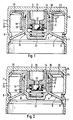
- the plunger shown consists of the cup-shaped housing 1, which consists of the hollow cylindrical wall 2 and the bottom 3, which is integral therewith.
- this housing an inner part 4 is arranged, which is formed from the disc part 5 and the cylindrical guide sleeve 6.
- the disk part 5 lies against the circumferential groove 8 formed in the hollow cylindrical wall and, on the other hand, is covered by the bead 9 formed out of the hollow cylindrical wall.
- the hydraulic lash adjuster 10 is mounted, which consists of the outer piston 11, which is slidably guided in the guide sleeve 6, and which in turn slides and receives the inner piston 12 with tight play.
- This has at its end facing the bottom 3 a central oil storage space 13, which is in fluid communication with an annular space 16 by means of the recess 14 in the inner surface 15 of the bottom 3, which is delimited by the inner piston 12 on the one hand and a sleeve 17 on the other, which itself over the cylindrical guide sleeve 6 extends in the direction from the bottom 3 to the vicinity of the disc part 5.
- the sleeve 17 is dimensioned such that it overlaps the guide sleeve 6 on the outside with its bore and has at least one circumferential point with a longitudinally extending groove-shaped formation 18 which, together with the guide sleeve 6, delimits a longitudinal channel 19 via which oil from the outside annular oil storage space 20 in the annular space 16 and from there can finally get into the central oil storage space 13. From there, the oil is fed into the high-pressure oil chamber 22 in a known manner via the check valve 21.
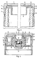
- the sleeve 17 is connected to the housing 1 in that at its end facing the bottom 3 it has a slightly inclined flange 23 which extends outwards and extends to the bore of the hollow cylindrical wall 2 and there in a short, passes axially away from the bottom 3 cylindrical collar 24 which fits snugly in the bore of the hollow cylindrical wall 2 and thereby creates a durable connection. If it is deemed necessary, the cylindrical collar 24 can additionally be welded to the bore of the wall 2 at its free end.
- Figure 2 differs from Figure 1 in that the flange 23 is supported against a shoulder 25 of the hollow cylindrical wall 2 so that it has no contact with the inner surface 15 of the bottom 3. At the same time, the sleeve 17 is supported with its end facing away from the bottom 3 on the disk part 5, so that a firm clamping connection is provided.
- the ring stamp 31 is in his Position before the material deformation of the wall 2 shown, while the right half shows the ring punch 31 in the position after the bead 30 has been shaped out of the wall 2.
- retaining lugs for the sleeve 17 can also be formed out of the wall 2 at individual circumferential locations.
- the ring stamp 31 has projections, the outer edges of which lie on a diameter that is larger than the diameter of the collar 24.
- a cylinder jacket 26 adjoins the radially outer edge of the disk part 5, which lies against the bore of the hollow cylindrical wall 2 and which in the example shown is produced in one piece with the inner part 4.
- this cylinder jacket 26, together with the wall 2 delimits a longitudinal channel 27 which is connected to an oil feed bore 28 at its end facing away from the base 3 and which opens into the oil reservoir 20 at its bottom end.
- the cylindrical collar 24 of the flange 23 is supported on the bottom end face of the cylinder jacket 26 and is therefore sufficiently fastened without additional measures being required for this
Landscapes
- Engineering & Computer Science (AREA)
- Mechanical Engineering (AREA)
- General Engineering & Computer Science (AREA)
- Valve-Gear Or Valve Arrangements (AREA)
- Valve Device For Special Equipments (AREA)
Claims (7)
Applications Claiming Priority (2)
| Application Number | Priority Date | Filing Date | Title |
|---|---|---|---|
| DE3810436 | 1988-03-26 | ||
| DE3810436A DE3810436A1 (de) | 1988-03-26 | 1988-03-26 | Sich selbsttaetig hydraulisch einstellender ventilstoessel |
Publications (2)
| Publication Number | Publication Date |
|---|---|
| EP0335121A1 EP0335121A1 (fr) | 1989-10-04 |
| EP0335121B1 true EP0335121B1 (fr) | 1991-11-27 |
Family
ID=6350852
Family Applications (1)
| Application Number | Title | Priority Date | Filing Date |
|---|---|---|---|
| EP89103618A Expired - Lifetime EP0335121B1 (fr) | 1988-03-26 | 1989-03-02 | Poussoir de soupape à réglage hydraulique automatique |
Country Status (5)
| Country | Link |
|---|---|
| US (1) | US4876997A (fr) |
| EP (1) | EP0335121B1 (fr) |
| JP (1) | JPH01280606A (fr) |
| DE (2) | DE3810436A1 (fr) |
| ES (1) | ES2028390T3 (fr) |
Families Citing this family (21)
| Publication number | Priority date | Publication date | Assignee | Title |
|---|---|---|---|---|
| DE8902780U1 (de) * | 1989-03-08 | 1989-04-20 | INA Wälzlager Schaeffler KG, 8522 Herzogenaurach | Sich selbsttätig hydraulisch einstellender Ventilstößel |
| DE4124184A1 (de) * | 1991-07-20 | 1993-01-21 | Schaeffler Waelzlager Kg | Hydraulischer tassenstoessel |
| DE4209440A1 (de) * | 1992-03-24 | 1993-09-30 | Schaeffler Waelzlager Kg | Tassenstößel mit hydraulischem Ventilspielausgleich |
| EP0591533A4 (fr) * | 1992-04-27 | 1994-10-19 | Nittan Valva | Dispositif de reglage de poussoir hydraulique a effet direct. |
| US5280771A (en) * | 1992-09-23 | 1994-01-25 | Eaton Corporation | Direct acting hydraulic tappet |
| DE4325610A1 (de) * | 1993-07-30 | 1995-02-02 | Schaeffler Waelzlager Kg | Tassenförmiger Ventilstößel |
| DE4332110A1 (de) * | 1993-09-22 | 1995-03-23 | Schaeffler Waelzlager Kg | Stößel mit hydraulischem Ventilspielausgleich |
| DE9408473U1 (de) * | 1994-05-21 | 1994-07-21 | INA Wälzlager Schaeffler KG, 91074 Herzogenaurach | Tassenförmiger Stößel |
| DE19724563A1 (de) * | 1997-06-11 | 1998-12-17 | Schaeffler Waelzlager Ohg | Tassenförmiger Ventilstößel |
| DE19728100B4 (de) * | 1997-07-02 | 2005-11-10 | Ina-Schaeffler Kg | Schaltbarer Stößel für einen Ventiltrieb einer Brennkraftmaschine |
| RU2143564C1 (ru) * | 1998-10-02 | 1999-12-27 | Вахрамов Николай Александрович | Гидравлическое устройство для компенсации зазоров в клапанном механизме двигателя внутреннего сгорания |
| RU2143565C1 (ru) * | 1998-11-30 | 1999-12-27 | Вахрамов Николай Александрович | Гидравлическое устройство для компенсации зазоров в клапанном механизме двигателя внутреннего сгорания |
| RU2143566C1 (ru) * | 1998-12-07 | 1999-12-27 | Вахрамов Николай Александрович | Гидравлическое устройство для компенсации зазоров в клапанном механизме двигателя внутреннего сгорания |
| RU2153587C1 (ru) * | 1999-04-06 | 2000-07-27 | Вахрамов Николай Александрович | Гидравлическое устройство для компенсации зазоров в клапанном механизме двигателя внутреннего сгорания |
| US7028654B2 (en) | 2002-10-18 | 2006-04-18 | The Maclean-Fogg Company | Metering socket |
| US7273026B2 (en) | 2002-10-18 | 2007-09-25 | Maclean-Fogg Company | Roller follower body |
| US6871622B2 (en) | 2002-10-18 | 2005-03-29 | Maclean-Fogg Company | Leakdown plunger |
| US7128034B2 (en) | 2002-10-18 | 2006-10-31 | Maclean-Fogg Company | Valve lifter body |
| US7191745B2 (en) | 2002-10-18 | 2007-03-20 | Maclean-Fogg Company | Valve operating assembly |
| DE102006045017A1 (de) * | 2006-09-23 | 2008-03-27 | Schaeffler Kg | Hydraulisches Abstützelement |
| DE102012104968A1 (de) * | 2012-06-08 | 2013-12-12 | Block Transformatoren-Elektronik Gmbh | Verspannvorrichtung zum Verspannen eines Kerns eines induktiven Geräts |
Family Cites Families (9)
| Publication number | Priority date | Publication date | Assignee | Title |
|---|---|---|---|---|
| US4590898A (en) * | 1979-12-05 | 1986-05-27 | Eaton Corporation | Hydraulic tappet for direct-acting valve gear |
| DE3006644A1 (de) * | 1980-02-22 | 1981-09-03 | Motomak Motorenbau, Maschinen- u. Werkzeugfabrik, Konstruktionen GmbH, 8070 Ingolstadt | Ventilstoessel fuer brennkraftmaschinen mit obenliegender nockenwelle |
| US4373477A (en) * | 1980-12-29 | 1983-02-15 | Eaton Corporation | Lash adjuster with plunger retainer |
| DE3437478A1 (de) * | 1984-10-12 | 1986-04-17 | INA Wälzlager Schaeffler KG, 8522 Herzogenaurach | Sich selbsttaetig hydraulisch einstellender ventilstoessel |
| DE3500425A1 (de) * | 1985-01-09 | 1986-07-10 | Motomak Motorenbau, Maschinen- u. Werkzeugfabrik, Konstruktionen GmbH, 8070 Ingolstadt | Hydraulischer tassenstoessel fuer verbrennungsmotoren |
| DE3528432A1 (de) * | 1985-08-08 | 1987-02-19 | Motomak | Sich selbsttaetig hydraulisch einstellender ventilstoessel |
| DE3542192A1 (de) * | 1985-11-29 | 1987-06-04 | Schaeffler Waelzlager Kg | Sich selbsttaetig hydraulisch einstellender ventilstoessel |
| DE3623638C2 (de) * | 1986-07-12 | 1994-02-24 | Schaeffler Waelzlager Kg | Sich selbsttätig hydraulisch einstellender Ventilstößel |
| DE3628619A1 (de) * | 1986-08-22 | 1988-03-03 | Schaeffler Waelzlager Kg | Sich selbsttaetig hydraulisch einstellender ventilstoessel |
-
1988
- 1988-03-26 DE DE3810436A patent/DE3810436A1/de not_active Withdrawn
-
1989
- 1989-02-27 US US07/316,467 patent/US4876997A/en not_active Expired - Fee Related
- 1989-03-02 ES ES198989103618T patent/ES2028390T3/es not_active Expired - Lifetime
- 1989-03-02 EP EP89103618A patent/EP0335121B1/fr not_active Expired - Lifetime
- 1989-03-02 DE DE8989103618T patent/DE58900484D1/de not_active Expired - Lifetime
- 1989-03-27 JP JP1072052A patent/JPH01280606A/ja active Pending
Also Published As
| Publication number | Publication date |
|---|---|
| DE3810436A1 (de) | 1989-10-12 |
| US4876997A (en) | 1989-10-31 |
| EP0335121A1 (fr) | 1989-10-04 |
| DE58900484D1 (de) | 1992-01-09 |
| JPH01280606A (ja) | 1989-11-10 |
| ES2028390T3 (es) | 1992-07-01 |
Similar Documents
| Publication | Publication Date | Title |
|---|---|---|
| EP0335121B1 (fr) | Poussoir de soupape à réglage hydraulique automatique | |
| EP0386474B1 (fr) | Poussoir de soupape à autoréglage hydraulique | |
| DE69208435T2 (de) | Druckflüssigkeitszylinder mit Druckübersetzer | |
| EP0570406B1 (fr) | Soupape a cartouche | |
| DE3006644A1 (de) | Ventilstoessel fuer brennkraftmaschinen mit obenliegender nockenwelle | |
| DE4092188C2 (de) | Rohrverbindung | |
| EP1619358A1 (fr) | Poussoir à actionnement cyclique pour un système de commande de soupape ou de pompe | |
| DE2942455A1 (de) | Laengenverstellbare gasfeder | |
| DE3412175A1 (de) | Tassenfoermiges gehaeuse eines sich selbsttaetig hydraulisch einstellenden ventilstoessels fuer brennkraftmaschinen mit obenliegender nockenwelle | |
| EP0179323B1 (fr) | Poussoir de soupape à réglage hydraulique automatique | |
| DE4325610A1 (de) | Tassenförmiger Ventilstößel | |
| EP0337242B1 (fr) | Poussoir de soupape à réglage hydraulique automatique | |
| WO1998016726A1 (fr) | Poussoir pour le mecanisme de distribution d'un moteur a combustion interne | |
| DE3709237A1 (de) | Schiebehuelse einer kfz-kupplung | |
| DE4092187C2 (de) | Rohrverbindung | |
| EP0224666B1 (fr) | Poussoir de soupape à autoréglage hydraulique | |
| DE3409235C2 (fr) | ||
| DE2063819A1 (de) | Sich selbsttätig hydraulisch einstellendes Spielausgleichselement für die Ventilsteuerung von Brennkraftmaschinen | |
| DE102014201911B4 (de) | Aktuator für einen elektrohydraulischen Gaswechselventiltrieb einer Brennkraftmaschine | |
| DE8808711U1 (de) | Sich selbsttätig hydraulisch einstellender Ventilstößel | |
| DE29822705U1 (de) | Geberzylinder für eine Fahrzeughydraulik | |
| DE19636203A1 (de) | Kolbenstangenführung für ein Kolben-Zylinderaggregat | |
| DE19652180A1 (de) | Stößel für einen Ventiltrieb einer Brennkraftmaschine | |
| DE3806974C2 (de) | Hydraulisch betätigbare Kupplung und Schleppwirkungsbremse | |
| EP0234343B1 (fr) | Elément interne pour élément hydraulique de compensation de jeu pour moteurs à combustion interne |
Legal Events
| Date | Code | Title | Description |
|---|---|---|---|
| PUAI | Public reference made under article 153(3) epc to a published international application that has entered the european phase |
Free format text: ORIGINAL CODE: 0009012 |
|
| 17P | Request for examination filed |
Effective date: 19890302 |
|
| AK | Designated contracting states |
Kind code of ref document: A1 Designated state(s): DE ES FR GB IT |
|
| 17Q | First examination report despatched |
Effective date: 19901126 |
|
| ITF | It: translation for a ep patent filed | ||
| GRAA | (expected) grant |
Free format text: ORIGINAL CODE: 0009210 |
|
| AK | Designated contracting states |
Kind code of ref document: B1 Designated state(s): DE ES FR GB IT |
|
| GBT | Gb: translation of ep patent filed (gb section 77(6)(a)/1977) | ||
| REF | Corresponds to: |
Ref document number: 58900484 Country of ref document: DE Date of ref document: 19920109 |
|
| ET | Fr: translation filed | ||
| REG | Reference to a national code |
Ref country code: ES Ref legal event code: FG2A Ref document number: 2028390 Country of ref document: ES Kind code of ref document: T3 |
|
| PLBE | No opposition filed within time limit |
Free format text: ORIGINAL CODE: 0009261 |
|
| STAA | Information on the status of an ep patent application or granted ep patent |
Free format text: STATUS: NO OPPOSITION FILED WITHIN TIME LIMIT |
|
| 26N | No opposition filed | ||
| PGFP | Annual fee paid to national office [announced via postgrant information from national office to epo] |
Ref country code: GB Payment date: 19940221 Year of fee payment: 6 |
|
| PGFP | Annual fee paid to national office [announced via postgrant information from national office to epo] |
Ref country code: FR Payment date: 19940307 Year of fee payment: 6 |
|
| PGFP | Annual fee paid to national office [announced via postgrant information from national office to epo] |
Ref country code: ES Payment date: 19940318 Year of fee payment: 6 |
|
| PG25 | Lapsed in a contracting state [announced via postgrant information from national office to epo] |
Ref country code: GB Effective date: 19950302 |
|
| PG25 | Lapsed in a contracting state [announced via postgrant information from national office to epo] |
Ref country code: ES Free format text: LAPSE BECAUSE OF NON-PAYMENT OF DUE FEES Effective date: 19950303 |
|
| GBPC | Gb: european patent ceased through non-payment of renewal fee |
Effective date: 19950302 |
|
| PG25 | Lapsed in a contracting state [announced via postgrant information from national office to epo] |
Ref country code: FR Free format text: LAPSE BECAUSE OF NON-PAYMENT OF DUE FEES Effective date: 19951130 |
|
| REG | Reference to a national code |
Ref country code: FR Ref legal event code: ST |
|
| REG | Reference to a national code |
Ref country code: ES Ref legal event code: FD2A Effective date: 19990405 |
|
| PGFP | Annual fee paid to national office [announced via postgrant information from national office to epo] |
Ref country code: DE Payment date: 20010316 Year of fee payment: 13 |
|
| PG25 | Lapsed in a contracting state [announced via postgrant information from national office to epo] |
Ref country code: DE Free format text: LAPSE BECAUSE OF NON-PAYMENT OF DUE FEES Effective date: 20021001 |
|
| PG25 | Lapsed in a contracting state [announced via postgrant information from national office to epo] |
Ref country code: IT Free format text: LAPSE BECAUSE OF NON-PAYMENT OF DUE FEES;WARNING: LAPSES OF ITALIAN PATENTS WITH EFFECTIVE DATE BEFORE 2007 MAY HAVE OCCURRED AT ANY TIME BEFORE 2007. THE CORRECT EFFECTIVE DATE MAY BE DIFFERENT FROM THE ONE RECORDED. Effective date: 20050302 |