EP0335456B2 - Mechanisch angetriebenes Bodenbearbeitungsgerät - Google Patents
Mechanisch angetriebenes Bodenbearbeitungsgerät Download PDFInfo
- Publication number
- EP0335456B2 EP0335456B2 EP89200748A EP89200748A EP0335456B2 EP 0335456 B2 EP0335456 B2 EP 0335456B2 EP 89200748 A EP89200748 A EP 89200748A EP 89200748 A EP89200748 A EP 89200748A EP 0335456 B2 EP0335456 B2 EP 0335456B2
- Authority
- EP
- European Patent Office
- Prior art keywords
- soil cultivating
- units
- tractor
- soil
- unit
- Prior art date
- Legal status (The legal status is an assumption and is not a legal conclusion. Google has not performed a legal analysis and makes no representation as to the accuracy of the status listed.)
- Expired - Lifetime
Links
- 239000002689 soil Substances 0.000 title claims description 98
- 238000010899 nucleation Methods 0.000 claims description 2
- 238000010276 construction Methods 0.000 description 3
- 230000005540 biological transmission Effects 0.000 description 2
- 239000000463 material Substances 0.000 description 2
- 241001236644 Lavinia Species 0.000 description 1
- 238000003971 tillage Methods 0.000 description 1
Images


Classifications
-
- A—HUMAN NECESSITIES
- A01—AGRICULTURE; FORESTRY; ANIMAL HUSBANDRY; HUNTING; TRAPPING; FISHING
- A01B—SOIL WORKING IN AGRICULTURE OR FORESTRY; PARTS, DETAILS, OR ACCESSORIES OF AGRICULTURAL MACHINES OR IMPLEMENTS, IN GENERAL
- A01B49/00—Combined machines
- A01B49/04—Combinations of soil-working tools with non-soil-working tools, e.g. planting tools
- A01B49/06—Combinations of soil-working tools with non-soil-working tools, e.g. planting tools for sowing or fertilising
- A01B49/065—Combinations of soil-working tools with non-soil-working tools, e.g. planting tools for sowing or fertilising the soil-working tools being actively driven
-
- A—HUMAN NECESSITIES
- A01—AGRICULTURE; FORESTRY; ANIMAL HUSBANDRY; HUNTING; TRAPPING; FISHING
- A01B—SOIL WORKING IN AGRICULTURE OR FORESTRY; PARTS, DETAILS, OR ACCESSORIES OF AGRICULTURAL MACHINES OR IMPLEMENTS, IN GENERAL
- A01B59/00—Devices specially adapted for connection between animals or tractors and agricultural machines or implements
- A01B59/04—Devices specially adapted for connection between animals or tractors and agricultural machines or implements for machines pulled or pushed by a tractor
- A01B59/048—Devices specially adapted for connection between animals or tractors and agricultural machines or implements for machines pulled or pushed by a tractor having pulling or pushing means arranged on the front part of the tractor
-
- A—HUMAN NECESSITIES
- A01—AGRICULTURE; FORESTRY; ANIMAL HUSBANDRY; HUNTING; TRAPPING; FISHING
- A01B—SOIL WORKING IN AGRICULTURE OR FORESTRY; PARTS, DETAILS, OR ACCESSORIES OF AGRICULTURAL MACHINES OR IMPLEMENTS, IN GENERAL
- A01B59/00—Devices specially adapted for connection between animals or tractors and agricultural machines or implements
- A01B59/06—Devices specially adapted for connection between animals or tractors and agricultural machines or implements for machines mounted on tractors
- A01B59/064—Devices specially adapted for connection between animals or tractors and agricultural machines or implements for machines mounted on tractors for connection to the front of the tractor
-
- A—HUMAN NECESSITIES
- A01—AGRICULTURE; FORESTRY; ANIMAL HUSBANDRY; HUNTING; TRAPPING; FISHING
- A01C—PLANTING; SOWING; FERTILISING
- A01C7/00—Sowing
- A01C7/20—Parts of seeders for conducting and depositing seed
- A01C7/208—Chassis; Coupling means to a tractor or the like; Lifting means; Side markers
-
- A—HUMAN NECESSITIES
- A01—AGRICULTURE; FORESTRY; ANIMAL HUSBANDRY; HUNTING; TRAPPING; FISHING
- A01C—PLANTING; SOWING; FERTILISING
- A01C7/00—Sowing
- A01C7/08—Broadcast seeders; Seeders depositing seeds in rows
- A01C7/081—Seeders depositing seeds in rows using pneumatic means
-
- A—HUMAN NECESSITIES
- A01—AGRICULTURE; FORESTRY; ANIMAL HUSBANDRY; HUNTING; TRAPPING; FISHING
- A01C—PLANTING; SOWING; FERTILISING
- A01C7/00—Sowing
- A01C7/20—Parts of seeders for conducting and depositing seed
- A01C7/201—Mounting of the seeding tools
- A01C7/203—Mounting of the seeding tools comprising depth regulation means
Definitions
- the invention relates to a power-driven soil cultivating machine comprising a frame, two soil cultivating units which are disposed on either side of said frame such that the distance between the units corresponds substantially to the customary width of a tractor and connecting means for connecting the frame with the said two cultivating units at the front side of the tractor while furthermore a third soil cultivating unit is provided, for mounting at the rear side of the tractor.
- EP-A-0 216 003 discloses a power driven soil cultivating machine comprising a frame, two soil cultivating units for preparing a seed bed, one being disposed on each side of the frame such that the distance between the units corresponds substantially to the customary width of a tractor.
- Connecting means are provided for connecting the frame, together with the two cultivating units, to the front side of a tractor and the two soil cultivating units are pivotable relative to the frame about pivot axes extending in the direction of operative travel of the machine.
- a third soil cultivating unit comprising a unit for preparing a seed bed is provided for mounting at the rear side of the tractor and has a working width which corresponds substantially to the spacing between the respective working widths of the two soil cultivating units.
- a single seed drill is located at the rear of the third unit for seeding across the total width of the soil cultivating machine.
- DE-A-2 324 677 discloses a power driven soil cultivating machine comprising a frame, a soil cultivating unit for preparing a seed bed disposed to one side of the frame and connecting means for connecting the frame, together with the soil cultivating unit to the front side of a tractor.
- a plough is provided for mounting at the rear of a tractor.
- the soil cultivating unit is supported by a side portion pivotably mounted on the frame about a first axis and the soil cultivating unit is in turn pivotably mounted on the side portion about a second axis, both axes extending in the direction of operative travel of the machine.
- the machine is arranged such that the soil cultivating unit can be positioned by pivoting about the axes to be operated on either side of the frame.
- a power-driven soil cultivating machine comprising a frame, two soil cultivating units for preparing a seed bed, such as rotary harrows, which units are disposed on either side of said frame such that the distance between the units corresponds substantially to the customary width of a tractor, and connecting means for connecting the frame with the said two cultivating units at the front side of the tractor, while furthermore a third soil cultivating unit is provided for mounting at the rear side of the tractor, whereby for each soil cultivating unit at the front side of the tractor a pivotal side portion is provided to support said soil cultivating unit, as well as a first pivot axis by means of which said pivotal side portion with the soil cultivating unit can pivot in respect to the frame and a second pivot axis by means of which the soil cultivating unit can pivot in respect to the pivotal side portion, both pivot axes extending in the direction of operative travel of the machine, while furthermore the third soil cultivating unit is constituted by a plough.
- a power-driven soil cultivating machine comprising a frame, two soil cultivating units for preparing a seed bed, such as rotary harrows, which units are disposed on either side of said frame such that the distance between the units corresponds substantially to the customary width of a tractor, and connecting means for connecting the frame with the said two cultivating units at the front side of the tractor, while furthermore a third soil cultivating unit is provided for mounting at the rear side of the tractor, whereby for each soil cultivating unit at the front side of the tractor a pivotal side portion is provided to support said soil cultivating unit, as well as a first pivot axis by means of which said pivotal side portion with the soil cultivating unit can pivot in respect to the frame and a second pivot axis by means of which the soil cultivating unit can pivot in respect to the pivotal sided portion, both pivot axes extending in the direction of operative travel of the machine, and a common seed drill is provided for the two soil cultivating units at the front side of the
- a machine combination is obtained, wherein soil cultivating units are used at both sides at the front side of the tractor and at the rear side of the tractor. Such machine combinations improve the efficiency of working the soil.
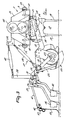
- the construction according to the invention as shown in the drawings comprises a tractor 1 and two soil cultivating units 2 arranged on either side at the front of the tractor.
- the two units 2 which during operation cultivate a strip of soil beside the tractor, are attached to a frame 3 which is connected to the three-point lifting hitch at the front side of the tractor 1 by means of a trestle 3A comprising a three-point connection.
- the frame 3 has a central portion 4, at which the trestle 3A is arranged.
- the central portion 4 comprises two transverse beams 5 which extend at least substantially parallel to each other and at least substantially horizontally.
- the beams 5 are interconnected by means of cross beams 5A which extend in the direction of operative travel A.
- each part 7 includes a beam 8 which extends in the direction of operative travel A and, in the region of the shafts 6, interconnects two parallel beams 9 extending parallel to the beams 5.
- each beam 8 is fitted with two diverging supports 10 whose other ends are located near the ends of a cross beam 11 which extends parallel to the beam 8 and is arranged between the beams 9.
- the ends of the beams 9 of each part 7 constitute the legs of a fork, between which there is arranged pivotably by means of supports 12 and shafts 13 a box-like frame portion 14, the said shafts 13 being in alignment and extending in the direction of operative travel.
- the frame portion 14 extends at least substantially parallel to the beams 9 of a part 7 and constitutes part of the soil cultivating-sad drill unit 2.
- the shafts 13 are fastened near the lower end of a bracket 15 which is fitted on a frame portion 14 near the midway point thereof. Inside the frame portion 14 there are supported at equal interspaces of preferably 25 cms the upwardly directed, preferably vertical, shafts 16 of soil working members 17.
- each of the soil working members 17 includes a carrier 18, said carrier having near its ends downwardly extending soil working elements 19 in the form of tines.
- the ends of each frame portion 14 are closed by means of plates 20 which extend upwardly and at least substantially parallel to the direction of operative travel A in a vertical plane. Near their leading sides, the plates 20 are provided with a pin 21, the arrangement being such that the pins 21 are in alignment.
- an arm 22 which extends rearwardly along a plate 20. Between the ends of the arms 22 there is supported freely rotatably about shafts 23 a roller 24.
- the frame portion 14 there is arranged between a support 25 on the bracket 15 and a cross beam 26 interconnecting the arms 22 an adjusting device 27, which device in this embodiment is constituted by a length-adjustable rod 28.
- the arms 22 With the aid of the rod 28 the arms 22 can be moved in the upward and downward direction by pivoting about the shafts 21 and be locked in a plurality of positions, the arrangement being such that this allows of a change in the position of the roller 24 relative to the soil working members and hence of an adjustment of the working depth of the soil working members.
- the rollers 24 are packer rollers provided at their rear sides with scrapers 29 which are connected to the cross beam 26 and extend to between the crowns of cams.
- a carrier 31 By means of arms 30 which are arranged pivotably about the shafts 23 of the roller 24 there is fitted behind the cross beam 26 a carrier 31, whereon seed coulters 32 are supported pivotably. Via tubes 33 the seed coulters 32 are connected to a distributor mechanism 34 of a common seed drill that with its hopper 35 is positioned on the central frame portion 4 of the frame 3.
- the frame portion 4 also carries a fan 36 which can be driven via a drive to be described hereinafter from the power take-off shaft at the front side of the tractor, as well as a feeding mechanism 37, with the aid of which seed material can be fed by the fan 36 from the hopper 35 to the distributor 34 which is positioned on the upper side of the hopper 35 and to which the tubes 33 are connected.
- each carrier 31 On the upper side of each carrier 31 there is arranged near its midway point a support 39 which is connected to the support 25 on the bracket 15 via a length-adjustable rod 40, the arrangement being such that, when the roller 24 is adjusted, the proper position of the seed coulters 32 can be set again.
- each carrier 31 At some distance from its ends, each carrier 31 is provided with a rearwardly extending pivotal arm 41. Between the ends of the arms 41 there is arranged pivotably by means of transverse pins 42 a carrier 43 carrying downwardly directed resilient tines 44. The tines 44 cover the furrows made by the seed coulters 32.
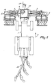
- the shafts 16 of the soil working members 17 are fitted with a pinion 45, the arrangement being such that the pinions 45 on the shafts 16 of adjacent soil working members 17 are in driving connection with each other.
- the shaft 16 of a soil working member is extended upwardly and reaches to into a gear box 46.
- the extended portion is in driving connection via a bevel gear transmission with a shaft 47 which extends transversely to the direction of operative travel A and is supported in the gear box, the said shaft being in driving connection via a speed variator 48 located at the outside of the gear box 46 with a superjacent shaft 49 projecting from the gear box at the inner side thereof.
- the projecting end of a shaft 49 is connected via a telescopic shaft 50 to a transverse shaft 50A in a gear box 51 fitted on the central frame portion 4 by means of a support 52.
- the shaft 50A is connected via a bevel gear transmission to a shaft drive 53 which extends in the direction of operative travel A, and projects from the gear box 51 at the rearside.
- the shaft 50A projects from the outer side of the gear box 51 and carries a pulley 54, a belt 55 being provided to drive the fan 36.
- the rear end of the shaft 53 is connected via an intermediate shaft 56 to the power-take off shaft at the front side of the tractor 1.
- the spacing between the strips of soil to be cultivated by the soil cultivating units 2 on either side of the factor 1 is such that it corresponds to the customary working width of a soil cultivating unit combined with a seed drill, which combination 60 can be hitched to the rear side of the tractor by means of the three-point lifting hitch (see Figure 1).
- the entire assembly can be moved in a direction indicated by arrow A, the drive for the soil cultivating machines, which, in this embodiment, are rotary harrows, and the drive for the fan 36 of the seed drill on the central frame portion 4 being derived from the front side drive of the tractor 1.
- the soil is worked to a predetermined depth by means of the soil cultivating machines of the units 2 and seed material can be introduced directly into this worked soil via the seed shares 32.
- the strip of soil between the units 2 can be worked and sown by means of the soil cultivating-seed drill combination 60 hitched to the rear side of and driven from the tractor without the tractor traveling over the worked soil.
- the soil cultivating-seed drill units 2 can be hinged upwardly about the shafts 6 by means of a hydraulic adjusting cylinder 57 (Fig. 4) which is arranged between the central frame portion 4 and a frame part 7 and is connected to the hydraulic circuit of the tractor.
- the lifting hitches at the front and rearsides of the tractor 1 ensure that the respective units are adjusted to the ultimate transport position.
- the side intended for feeding the seed to the lifted unit 2 can be closed by a Bowden cable 59 to be operated from the tractor 1, so that the seed will be transported to the seed coulters mounted to the cultivating unit that will be in operation.
- the seed drill could be in operation with or without the tillage unit being in operation.
- the left hand unit of the machine could be in operation independently of the unit at the right hand side.
- the unit of the right hand side could be in operation independently of the unit of the left hand side.
Landscapes
- Life Sciences & Earth Sciences (AREA)
- Soil Sciences (AREA)
- Environmental Sciences (AREA)
- Engineering & Computer Science (AREA)
- Mechanical Engineering (AREA)
- Zoology (AREA)
- Soil Working Implements (AREA)
- Agricultural Machines (AREA)
Claims (7)
- Motorbetriebene Bodenbearbeitungsmaschine mit einem Gestell (3), zwei Bodenbearbeitungseinheiten (2) wie z. B. Kreiseleggen zur Bereitung eines Saatbettes, die beiderseits des Gestells (3) derart angeordnet sind, daß der Abstand zwischen den Einheiten im wesentlichen der üblichen Breite eines Schleppers (1) entspricht, und mit Verbindungsvorrichtungen (3A) zum Verbinden des Gestells (3) mit den beiden Bodenbearbeitungseinheiten (2) an der Frontseite des Schleppers (1), wobei weiterhin eine dritte Bodenbearbeitungseinheit vorgesehen ist, die an die Heckseite des Schleppers (1) anzuschließen ist, wobei für jede an der Frontseite des Schleppers (1) befindliche Bodenbearbeitungseinheit (2) ein schwenkbewegliches Seitenteil (7) zur Abstützung der Bodenbearbeitungseinheit (2) sowie eine erste Schwenkachse (6) vorgesehen ist, mittels der das schwenkbewegliche Seitenteil (7) mit der Bodenbearbeitungseinheit (2) in bezug auf das Gestell (3) schwenken kann, wobei eine zweite Schwenkachse (13) vorhanden ist, mittels der die Bodenbearbeitungseinheit (2) in bezug auf das schwenkbewegliche Seitenteil (7) schwenkbar ist, wobei sich beide Schwenkachsen (6, 13) in Arbeitsrichtung (A) der Maschine erstrecken, und wobei ferner die dritte Bodenbearbeitungseinheit durch einen Pflug (58) gebildet ist.
- Motorbetriebene Bodenbearbeitungsmaschine mit einem Gestell (3), zwei Bodenbearbeitungseinheiten (2) wie z. B. Kreiseleggen zur Bereitung eines Saatbettes, die beiderseits des Gestells (3) derart angeordnet sind, daß der Abstand zwischen den Einheiten im wesentlichen der üblichen Breite eines Schleppers (1) entspricht, und mit Verbindungsvorrichtungen (3A) zum Verbinden des Gestells (3) mit den beiden Bodenbearbeitungseinheiten (2) an der Frontseite des Schleppers (1), wobei weiterhin eine dritte Bodenbearbeitungseinheit vorgesehen ist, die an die Heckseite des Schleppers (1) anzuschließen ist, wobei für jede an der Frontseite des Schleppers (1) befindliche Bodenbearbeitungseinheit (2) ein schwenkbewegliches Seitenteil (7) zur Abstützung der Bodenbearbeitungseinheit (2) sowie eine erste Schwenkachse (6) vorgesehen ist, mittels der das schwenkbewegliche Seitenteil (7) mit der Bodenbearbeitungseinheit (2) in bezug auf das Gestell (3) schwenken kann, wobei eine zweite Schwenkachse (13) vorhanden ist, mittels der die Bodenbearbeitungseinheit (2) in bezug auf das schwenkbewegliche Seitenteil (7) schwenkbar ist, wobei sich beide Schwenkachsen (6, 13) in Arbeitsrichtung (A) der Maschine erstrecken, wobei für die beiden Bodenbearbeitungseinheiten an der Frontseite des Schleppers eine gemeinsame Drillsaatmaschine vorgesehen ist, die zwischen den Bodenbearbeitungseinheiten angeordnet ist, und wobei ferner die dritte Bodenbearbeitungseinheit durch eine Einheit zur Bereitung eines Saatbettes (60) wie z. B. eine Kreiselegge gebildet ist, die eine Arbeitsbreite hat, welche im wesentlichen dem Abstand zwischen den jeweiligen Arbeitsbreiten der beiden Bodenbearbeitungseinheiten entspricht.
- Bodenbearbeitungsmaschine nach Anspruch 2,
bei der die Gesamtarbeitsbreite der an der Frontseite des Schleppers (1) befindlichen Bodenbearbeitungseinheiten (2) und der Abstand zwischen den Bodenbearbeitungseinheiten (2) etwa 6 m betragen. - Bodenbearbeitungsmaschine nach Anspruch 2, 3 oder 4,
dadurch gekennzeichnet, daß die Drillsaatmaschine (33 bis 37) auf einem Gestell (3) angeordnet ist, das auch die Bodenbearbeitungseinheiten (2) abstützt. - Bodenbearbeitungsmaschine nach einem der Ansprüche 2 bis 4,
dadurch gekennzeichnet, daß Säschare (32) hinter einer Bodenbearbeitungseinheit (2) angeordnet und mit einem Verteilermechanismus (34) der Drillsaatmaschine (33 bis 37) über Schläuche (33) verbunden sind. - Bodenbearbeitungsmaschine nach Anspruch 5,
dadurch gekennzeichnet, daß die Säschare (32) von einen Träger (31) abgestützt sind, der um die Achsen (23) einer Walze (24) verstellbar ist, welche eine Bodenbearbeitungseinheit (2) abstützt. - Bodenbearbeitungsmaschine nach einem der Ansprüche 2 bis 6,
dadurch gekennzeichnet, daß die Drillsaatmaschine (33 bis 37) für die Bodenbearbeitungseinheiten (2) eine pneumatische Drillmaschine ist, bei der der Verteilermechanismus (34), an den die Schläuche (33) für die Säschare (32) angeschlossen sind, zum Säen auf der linken bzw. der rechten Seite wahlweise zu schließen ist.
Applications Claiming Priority (2)
| Application Number | Priority Date | Filing Date | Title |
|---|---|---|---|
| NL8800800 | 1988-03-30 | ||
| NL8800800A NL8800800A (nl) | 1988-03-30 | 1988-03-30 | Combinatie van een trekker met ten minste een grondbewerking-zaaieenheid. |
Publications (3)
| Publication Number | Publication Date |
|---|---|
| EP0335456A1 EP0335456A1 (de) | 1989-10-04 |
| EP0335456B1 EP0335456B1 (de) | 1992-12-16 |
| EP0335456B2 true EP0335456B2 (de) | 1997-09-24 |
Family
ID=19852031
Family Applications (4)
| Application Number | Title | Priority Date | Filing Date |
|---|---|---|---|
| EP89200749A Expired - Lifetime EP0337534B1 (de) | 1988-03-30 | 1989-03-23 | Bodenbearbeitungsmaschine |
| EP89200746A Expired - Lifetime EP0337533B1 (de) | 1988-03-30 | 1989-03-23 | Mechanisch angetriebenes Bodenbearbeitungsgerät |
| EP89200748A Expired - Lifetime EP0335456B2 (de) | 1988-03-30 | 1989-03-23 | Mechanisch angetriebenes Bodenbearbeitungsgerät |
| EP89200747A Expired - Lifetime EP0335455B1 (de) | 1988-03-30 | 1989-03-23 | Kombinierte Drill- und Bodenbearbeitungsmaschine |
Family Applications Before (2)
| Application Number | Title | Priority Date | Filing Date |
|---|---|---|---|
| EP89200749A Expired - Lifetime EP0337534B1 (de) | 1988-03-30 | 1989-03-23 | Bodenbearbeitungsmaschine |
| EP89200746A Expired - Lifetime EP0337533B1 (de) | 1988-03-30 | 1989-03-23 | Mechanisch angetriebenes Bodenbearbeitungsgerät |
Family Applications After (1)
| Application Number | Title | Priority Date | Filing Date |
|---|---|---|---|
| EP89200747A Expired - Lifetime EP0335455B1 (de) | 1988-03-30 | 1989-03-23 | Kombinierte Drill- und Bodenbearbeitungsmaschine |
Country Status (4)
| Country | Link |
|---|---|
| EP (4) | EP0337534B1 (de) |
| DE (4) | DE68903856T3 (de) |
| ES (1) | ES2036790T5 (de) |
| NL (1) | NL8800800A (de) |
Families Citing this family (10)
| Publication number | Priority date | Publication date | Assignee | Title |
|---|---|---|---|---|
| FR2702628B1 (fr) * | 1993-03-19 | 1995-05-05 | Kuhn Sa | Machine agricole de travail du sol de grande largeur s'adaptant mieux au relief du sol. |
| DE19522709A1 (de) † | 1995-06-22 | 1997-01-02 | Amazonen Werke Dreyer H | Sämaschine |
| DE19529797C2 (de) * | 1995-08-12 | 2001-08-30 | Rauch Landmaschfab Gmbh | Landwirtschaftliche Geräteeinheit, bestehend aus einem Bodenbearbeitungsgerät und einer pneumatischen Sämaschine |
| NL1005026C1 (nl) * | 1996-10-25 | 1998-04-28 | Maasland Nv | Landbouwmachine. |
| FR3001606B1 (fr) * | 2013-02-07 | 2015-12-04 | Jean Joseph Picq | Combine d'outils agricole dispose a l'avant d'un tracteur preparant le sol pour semis de toutes cereales |
| DE102014000692A1 (de) * | 2014-01-15 | 2015-07-16 | Olgierd Mariusz Lemanski | Schwenkvorrichtung für eine Kombination von Saatbettbereitungseinheit und pneumatischer Sämaschine die zusammen mit einem Volldrehpflug auf eine Zugmaschine angebaut werden kann |
| CN108260370A (zh) * | 2018-03-28 | 2018-07-10 | 中国农业科学院草原研究所 | 一种旋耕整地气吸小粒种子精量播种联合机组及方法 |
| US11134608B2 (en) | 2018-05-15 | 2021-10-05 | Deere & Company | Method and machine for plant cultivation on a field |
| DE102019007751A1 (de) * | 2019-11-08 | 2021-05-12 | Maschinenfabrik Bernard Krone GmbH & Co. KG | Anbauvorrichtung zum Anbauen von mindestens einer landwirtschaftlichen Arbeitsmaschine an eine Zugmaschine sowie Arbeitszug mit der Zugmaschine, der Anbauvorrichtung und der landwirtschaftlichen Arbeitsmaschine |
| DE102023129137A1 (de) * | 2023-10-24 | 2025-04-24 | Amazonen-Werke H. Dreyer SE & Co. KG | Frontanbau zum Verbinden mit einem Frontanschluss einer Zugmaschine sowie Maschinensystem mit einem Frontanbau |
Family Cites Families (8)
| Publication number | Priority date | Publication date | Assignee | Title |
|---|---|---|---|---|
| US3128729A (en) * | 1960-05-24 | 1964-04-14 | James A Henson | All-purpose farm machine |
| US3265137A (en) * | 1964-02-13 | 1966-08-09 | Chester F Couser | Ground conditioning implement |
| US3224392A (en) * | 1964-09-08 | 1965-12-21 | Mellen William Fisk | Soil tillage apparatus |
| DE3148679A1 (de) * | 1981-12-09 | 1983-07-21 | Ernst 7326 Heiningen Weichel | Bestell-schlepper |
| DE3512658A1 (de) * | 1985-04-06 | 1986-10-16 | Ernst 7326 Heiningen Weichel | Verfahren und geraetesystem zur bodenlockerung, saatbettherrichtung und bestellung |
| DE3666319D1 (en) * | 1985-04-11 | 1989-11-23 | Lely Nv C Van Der | A plough |
| NL8501109A (nl) * | 1985-04-16 | 1986-11-17 | Lely Nv C Van Der | Landbouwwerktuig. |
| FR2622762A1 (fr) * | 1987-11-10 | 1989-05-12 | Mach Agricoles Cie Fse | Machine agricole pour le travail du sol,destinee a etre montee a l'avant d'un tracteur |
-
1988
- 1988-03-30 NL NL8800800A patent/NL8800800A/nl not_active Application Discontinuation
-
1989
- 1989-03-23 DE DE68903856T patent/DE68903856T3/de not_active Expired - Fee Related
- 1989-03-23 EP EP89200749A patent/EP0337534B1/de not_active Expired - Lifetime
- 1989-03-23 DE DE68913786T patent/DE68913786T2/de not_active Expired - Fee Related
- 1989-03-23 EP EP89200746A patent/EP0337533B1/de not_active Expired - Lifetime
- 1989-03-23 DE DE8989200746T patent/DE68904795T2/de not_active Expired - Fee Related
- 1989-03-23 EP EP89200748A patent/EP0335456B2/de not_active Expired - Lifetime
- 1989-03-23 EP EP89200747A patent/EP0335455B1/de not_active Expired - Lifetime
- 1989-03-23 DE DE8989200747T patent/DE68904790T2/de not_active Expired - Fee Related
- 1989-03-23 ES ES89200748T patent/ES2036790T5/es not_active Expired - Lifetime
Also Published As
| Publication number | Publication date |
|---|---|
| DE68904795T2 (de) | 1993-09-02 |
| EP0335455A1 (de) | 1989-10-04 |
| EP0337534A3 (en) | 1990-01-17 |
| NL8800800A (nl) | 1989-10-16 |
| EP0337533A2 (de) | 1989-10-18 |
| DE68913786T2 (de) | 1994-10-27 |
| EP0335456B1 (de) | 1992-12-16 |
| EP0335455B1 (de) | 1993-02-10 |
| ES2036790T3 (es) | 1993-06-01 |
| DE68903856D1 (de) | 1993-01-28 |
| DE68903856T2 (de) | 1993-07-08 |
| EP0337534B1 (de) | 1994-03-16 |
| DE68904795D1 (de) | 1993-03-25 |
| EP0337533B1 (de) | 1993-02-10 |
| EP0335456A1 (de) | 1989-10-04 |
| EP0337533A3 (en) | 1990-02-14 |
| DE68903856T3 (de) | 1998-04-16 |
| ES2036790T5 (es) | 1998-01-16 |
| DE68904790T2 (de) | 1993-09-02 |
| DE68904790D1 (de) | 1993-03-25 |
| EP0337534A2 (de) | 1989-10-18 |
| DE68913786D1 (de) | 1994-04-21 |
Similar Documents
| Publication | Publication Date | Title |
|---|---|---|
| US4108089A (en) | Agricultural implements | |
| US4036154A (en) | Soil cultivating implements | |
| US3810434A (en) | Agricultural cultivator and seed frill combinations | |
| EP0271119B1 (de) | Bodenbearbeitungsmaschine | |
| EP0335456B2 (de) | Mechanisch angetriebenes Bodenbearbeitungsgerät | |
| EP0198563B1 (de) | Landwirtschaftliche Maschine | |
| US3826314A (en) | Cultivating implements | |
| US3899029A (en) | Rotary harrows | |
| RU2420051C2 (ru) | Сельскохозяйственная машина | |
| EP0199406B1 (de) | Pflug | |
| EP0422721A1 (de) | Landwirtschaftliches Gerät, insbesondere Bodenbearbeitungsmaschine | |
| US2337662A (en) | Agricultural implement | |
| EP0506210B1 (de) | Streuer | |
| EP0436975B1 (de) | Bodenbearbeitungsmaschine | |
| EP0620962B1 (de) | Bodenbearbeitungsmaschine | |
| EP0432815A2 (de) | Landwirtschaftliche Maschine | |
| EP0288125B1 (de) | Bodenbearbeitungsmaschine | |
| EP0305601B1 (de) | Gerät zur Bodenbearbeitung | |
| US4147117A (en) | Cultivating implements | |
| EP0201135B1 (de) | Bodenbearbeitungsmaschine | |
| EP0269183B1 (de) | Bodenbearbeitungsmaschine | |
| EP0429138A1 (de) | Bodenbearbeitungsmaschine | |
| EP0252555B1 (de) | Bodenbearbeitungsmaschine | |
| GB2145311A (en) | Cultivators | |
| NL8902833A (nl) | Landbouwwerktuig, in het bijzonder een grondbewerkingsmachine. |
Legal Events
| Date | Code | Title | Description |
|---|---|---|---|
| PUAI | Public reference made under article 153(3) epc to a published international application that has entered the european phase |
Free format text: ORIGINAL CODE: 0009012 |
|
| AK | Designated contracting states |
Kind code of ref document: A1 Designated state(s): DE ES FR GB IT NL |
|
| 17P | Request for examination filed |
Effective date: 19900314 |
|
| 17Q | First examination report despatched |
Effective date: 19901212 |
|
| GRAA | (expected) grant |
Free format text: ORIGINAL CODE: 0009210 |
|
| AK | Designated contracting states |
Kind code of ref document: B1 Designated state(s): DE ES FR GB IT NL |
|
| REF | Corresponds to: |
Ref document number: 68903856 Country of ref document: DE Date of ref document: 19930128 |
|
| ITF | It: translation for a ep patent filed | ||
| ET | Fr: translation filed | ||
| REG | Reference to a national code |
Ref country code: ES Ref legal event code: FG2A Ref document number: 2036790 Country of ref document: ES Kind code of ref document: T3 |
|
| PLBI | Opposition filed |
Free format text: ORIGINAL CODE: 0009260 |
|
| 26 | Opposition filed |
Opponent name: RABEWERK GMBH + CO. Effective date: 19930709 |
|
| NLR1 | Nl: opposition has been filed with the epo |
Opponent name: RABEWERK GMBH |
|
| PLAW | Interlocutory decision in opposition |
Free format text: ORIGINAL CODE: EPIDOS IDOP |
|
| PLAW | Interlocutory decision in opposition |
Free format text: ORIGINAL CODE: EPIDOS IDOP |
|
| PUAH | Patent maintained in amended form |
Free format text: ORIGINAL CODE: 0009272 |
|
| STAA | Information on the status of an ep patent application or granted ep patent |
Free format text: STATUS: PATENT MAINTAINED AS AMENDED |
|
| 27A | Patent maintained in amended form |
Effective date: 19970924 |
|
| AK | Designated contracting states |
Kind code of ref document: B2 Designated state(s): DE ES FR GB IT NL |
|
| NLR2 | Nl: decision of opposition | ||
| ITF | It: translation for a ep patent filed | ||
| REG | Reference to a national code |
Ref country code: ES Ref legal event code: DC2A Kind code of ref document: T5 Effective date: 19971216 |
|
| ET3 | Fr: translation filed ** decision concerning opposition | ||
| NLR3 | Nl: receipt of modified translations in the netherlands language after an opposition procedure | ||
| PGFP | Annual fee paid to national office [announced via postgrant information from national office to epo] |
Ref country code: ES Payment date: 20010406 Year of fee payment: 13 |
|
| REG | Reference to a national code |
Ref country code: GB Ref legal event code: IF02 |
|
| PGFP | Annual fee paid to national office [announced via postgrant information from national office to epo] |
Ref country code: FR Payment date: 20020304 Year of fee payment: 14 |
|
| PGFP | Annual fee paid to national office [announced via postgrant information from national office to epo] |
Ref country code: NL Payment date: 20020305 Year of fee payment: 14 |
|
| PGFP | Annual fee paid to national office [announced via postgrant information from national office to epo] |
Ref country code: GB Payment date: 20020320 Year of fee payment: 14 Ref country code: DE Payment date: 20020320 Year of fee payment: 14 |
|
| PG25 | Lapsed in a contracting state [announced via postgrant information from national office to epo] |
Ref country code: GB Free format text: LAPSE BECAUSE OF NON-PAYMENT OF DUE FEES Effective date: 20030323 |
|
| PG25 | Lapsed in a contracting state [announced via postgrant information from national office to epo] |
Ref country code: ES Free format text: LAPSE BECAUSE OF NON-PAYMENT OF DUE FEES Effective date: 20030324 |
|
| PG25 | Lapsed in a contracting state [announced via postgrant information from national office to epo] |
Ref country code: NL Free format text: LAPSE BECAUSE OF NON-PAYMENT OF DUE FEES Effective date: 20031001 Ref country code: DE Free format text: LAPSE BECAUSE OF NON-PAYMENT OF DUE FEES Effective date: 20031001 |
|
| GBPC | Gb: european patent ceased through non-payment of renewal fee |
Effective date: 20030323 |
|
| PG25 | Lapsed in a contracting state [announced via postgrant information from national office to epo] |
Ref country code: FR Free format text: LAPSE BECAUSE OF NON-PAYMENT OF DUE FEES Effective date: 20031127 |
|
| NLV4 | Nl: lapsed or anulled due to non-payment of the annual fee |
Effective date: 20031001 |
|
| REG | Reference to a national code |
Ref country code: FR Ref legal event code: ST |
|
| REG | Reference to a national code |
Ref country code: ES Ref legal event code: FD2A Effective date: 20030324 |
|
| PG25 | Lapsed in a contracting state [announced via postgrant information from national office to epo] |
Ref country code: IT Free format text: LAPSE BECAUSE OF NON-PAYMENT OF DUE FEES Effective date: 20050323 |