EP0335464A1 - Procédé et dispositif pour travailler des pièces en bois - Google Patents
Procédé et dispositif pour travailler des pièces en bois Download PDFInfo
- Publication number
- EP0335464A1 EP0335464A1 EP89200769A EP89200769A EP0335464A1 EP 0335464 A1 EP0335464 A1 EP 0335464A1 EP 89200769 A EP89200769 A EP 89200769A EP 89200769 A EP89200769 A EP 89200769A EP 0335464 A1 EP0335464 A1 EP 0335464A1
- Authority
- EP
- European Patent Office
- Prior art keywords
- clamping
- machining
- machining operation
- bench
- devices
- Prior art date
- Legal status (The legal status is an assumption and is not a legal conclusion. Google has not performed a legal analysis and makes no representation as to the accuracy of the status listed.)
- Withdrawn
Links
- 238000003754 machining Methods 0.000 title claims abstract description 186
- 238000000034 method Methods 0.000 title claims abstract description 24
- 238000009434 installation Methods 0.000 claims abstract description 36
- 230000003134 recirculating effect Effects 0.000 claims description 2
- 230000001360 synchronised effect Effects 0.000 claims description 2
- 230000000875 corresponding effect Effects 0.000 description 4
- 238000004519 manufacturing process Methods 0.000 description 4
- 238000003801 milling Methods 0.000 description 4
- 238000007493 shaping process Methods 0.000 description 4
- 238000012937 correction Methods 0.000 description 2
- 238000013461 design Methods 0.000 description 2
- 230000006870 function Effects 0.000 description 2
- 238000012423 maintenance Methods 0.000 description 2
- 239000000463 material Substances 0.000 description 2
- 239000000047 product Substances 0.000 description 2
- 238000010276 construction Methods 0.000 description 1
- 238000010924 continuous production Methods 0.000 description 1
- 239000011265 semifinished product Substances 0.000 description 1
- 238000004904 shortening Methods 0.000 description 1
- 238000003860 storage Methods 0.000 description 1
- 238000012546 transfer Methods 0.000 description 1
- 239000002023 wood Substances 0.000 description 1
Images

Classifications
-
- B—PERFORMING OPERATIONS; TRANSPORTING
- B23—MACHINE TOOLS; METAL-WORKING NOT OTHERWISE PROVIDED FOR
- B23Q—DETAILS, COMPONENTS, OR ACCESSORIES FOR MACHINE TOOLS, e.g. ARRANGEMENTS FOR COPYING OR CONTROLLING; MACHINE TOOLS IN GENERAL CHARACTERISED BY THE CONSTRUCTION OF PARTICULAR DETAILS OR COMPONENTS; COMBINATIONS OR ASSOCIATIONS OF METAL-WORKING MACHINES, NOT DIRECTED TO A PARTICULAR RESULT
- B23Q7/00—Arrangements for handling work specially combined with or arranged in, or specially adapted for use in connection with, machine tools, e.g. for conveying, loading, positioning, discharging, sorting
- B23Q7/03—Arrangements for handling work specially combined with or arranged in, or specially adapted for use in connection with, machine tools, e.g. for conveying, loading, positioning, discharging, sorting by means of endless chain conveyors
- B23Q7/035—Arrangements for handling work specially combined with or arranged in, or specially adapted for use in connection with, machine tools, e.g. for conveying, loading, positioning, discharging, sorting by means of endless chain conveyors on which work holders are fixed
-
- B—PERFORMING OPERATIONS; TRANSPORTING
- B27—WORKING OR PRESERVING WOOD OR SIMILAR MATERIAL; NAILING OR STAPLING MACHINES IN GENERAL
- B27M—WORKING OF WOOD NOT PROVIDED FOR IN SUBCLASSES B27B - B27L; MANUFACTURE OF SPECIFIC WOODEN ARTICLES
- B27M1/00—Working of wood not provided for in subclasses B27B - B27L, e.g. by stretching
- B27M1/08—Working of wood not provided for in subclasses B27B - B27L, e.g. by stretching by multi-step processes
-
- Y—GENERAL TAGGING OF NEW TECHNOLOGICAL DEVELOPMENTS; GENERAL TAGGING OF CROSS-SECTIONAL TECHNOLOGIES SPANNING OVER SEVERAL SECTIONS OF THE IPC; TECHNICAL SUBJECTS COVERED BY FORMER USPC CROSS-REFERENCE ART COLLECTIONS [XRACs] AND DIGESTS
- Y10—TECHNICAL SUBJECTS COVERED BY FORMER USPC
- Y10T—TECHNICAL SUBJECTS COVERED BY FORMER US CLASSIFICATION
- Y10T29/00—Metal working
- Y10T29/51—Plural diverse manufacturing apparatus including means for metal shaping or assembling
- Y10T29/5124—Plural diverse manufacturing apparatus including means for metal shaping or assembling with means to feed work intermittently from one tool station to another
-
- Y—GENERAL TAGGING OF NEW TECHNOLOGICAL DEVELOPMENTS; GENERAL TAGGING OF CROSS-SECTIONAL TECHNOLOGIES SPANNING OVER SEVERAL SECTIONS OF THE IPC; TECHNICAL SUBJECTS COVERED BY FORMER USPC CROSS-REFERENCE ART COLLECTIONS [XRACs] AND DIGESTS
- Y10—TECHNICAL SUBJECTS COVERED BY FORMER USPC
- Y10T—TECHNICAL SUBJECTS COVERED BY FORMER US CLASSIFICATION
- Y10T29/00—Metal working
- Y10T29/51—Plural diverse manufacturing apparatus including means for metal shaping or assembling
- Y10T29/5196—Multiple station with conveyor
-
- Y—GENERAL TAGGING OF NEW TECHNOLOGICAL DEVELOPMENTS; GENERAL TAGGING OF CROSS-SECTIONAL TECHNOLOGIES SPANNING OVER SEVERAL SECTIONS OF THE IPC; TECHNICAL SUBJECTS COVERED BY FORMER USPC CROSS-REFERENCE ART COLLECTIONS [XRACs] AND DIGESTS
- Y10—TECHNICAL SUBJECTS COVERED BY FORMER USPC
- Y10T—TECHNICAL SUBJECTS COVERED BY FORMER US CLASSIFICATION
- Y10T409/00—Gear cutting, milling, or planing
- Y10T409/30—Milling
- Y10T409/304536—Milling including means to infeed work to cutter
- Y10T409/305264—Multiple work stations
Definitions
- the invention relates primarily to a procedure for machining one or more wooden articles, in order to proceed from an initial shape to a final shape, wherein: - each wooden article is subjected to a series of successive machining operations, - each machining operation takes place in a machining operation station which contains machining tools, while - during each machining operation the wooden article is held firmly on a clamping bench with the aid of mechanical clamping devices, and - the article is removed from the particular station at the end of each machining operation.
- Netherlands Patent 104 722 describes a so-called tenoning machine wherein a procedure is carried out with which an article is provided with a projecting tenon in a number of steps.
- the steps of the procedure are such that the part of the wooden article which does not form part of the tenon is removed, for example by means of milling, so that finally the wooden article with the tenon shaped by milling remains.
- Other types of machining which arise in the woodworking industry, such as, for example, for furniture are, for example, cut-down and cut-up milling. These terms signify the shaping, by means of milling, of a recess in or, respectively, relief on the surface of the wooden part, which takes place when shaping arm rests and table and chair legs.
- Another type of machining can be the sanding of the wooden part.
- Yet another type of machining can be the shaping of so-called punched or slotted holes.
- the present invention has the aim of providing a solution for the above-mentioned disadvantage and relates to a procedure of the type indicated above, which procedure is characterized in that the machining operations are carried out successively in a series of machining operation stations and in that a wooden article remains clamped in one and the same clamping bench for undergoing all machining operations, the said bench being moved between the machining operations and being fixed successively in each of the machining operation stations of the series, after which machining takes place, and the article is removed from its clamping bench after having passed through all machining operations in all stations.
- a wooden article to be machined is therefore always clamped on the same clamping bench, while the wooden article is at all times kept in the same position relative to the particular clamping bench by means of suitable clamping devices.
- the procedure is always such that in a first step the new clamping devices to be used are brought into clamping contact with the article to be clamped and that the clamping devices previously used are then removed.
- clamping devices which can be coupled and which can move with the clamping bench and/or stationary clamping devices connected to the machining operation station.
- each clamping bench can be present on each clamping bench, all of which are machined in one machining operation station before moving the clamping bench from a fixed position in one machining operation station to a fixed position in another machining operation station.
- the procedure according to the invention is appropriately carried in such a way that during the movement of a clamping bench between the machining operations a wooden article is clamped with the aid of the clamping devices which can be coupled and moved with the clamping bench, in that, after arrival and fixing of a clamping bench in a machining operation station, the clamping of the wooden article is taken over by one or more other stationary clamping devices connected to the machining operation station, the clamping devices which can be coupled and move with the bench are detached and returned to the previous machining operation station and machining operations are carried out on the wooden article on the clamping bench before and/or after the clamping is taken over.
- clamping devices which can be coupled can also be incorporated in an endless conveyor system so that they always move in the same direction as the benches.
- a new clamping bench with a new wooden article clamped thereon is fed to the first machining operation station and, if such is present, a clamping bench with the machined wooden article clamped thereon is removed from the final machining operation station, while, if more than one clamping bench is present, all of the machining operations, corresponding in number to the number of clamping benches, are first completed before the clamping benches are moved.
- the above measure indicates that by supplying a new clamping bench with an unmachined article or unmachined articles to the first station after each machining operation (or series of machining operations in one and the same station) and, if after some time clamping benches provided with one or more wooden articles are present in all stations, removing a clamping bench from the last station, a continuous process can be realised.
- the machining operations are adjusted such that they all take approximately the same period of time.
- the significance of this measure is that if a series of machining operations includes one machining operation which is particularly time-consuming compared with the other machining operations, this long machining operation can be broken down to give a larger number of machining operations which take a time which better corresponds to the time taken by the other machining operations.
- the invention also relates to an installation for the machining of one or more wooden articles and made up of several machining operation stations, each station consisting, during its functioning, of at least: - a clamping bench with clamping devices for clamping and positioning one or more identical wooden articles to be machined, - machining tools, and - driving and control devices for the machining tools, in which the clamping devices consist of stationary clamping devices which are fixed in position relative to a machining operation station and clamping devices which can be coupled to the clamping bench and can move with the clamping bench; the installation comprises devices for the synchronous moving of each of the clamping benches from a fixed position relative to a machining operation station to a fixed position relative to another machining operation station and means are present for actuating the various clamping devices as desired in a machining operation station, but such that one or more clamping devices continuously exert their clamping action on the wooden article, and in that clamping bench fixing devices are present for fixing a clamping bench in a machining operation station.
- the installation according to the invention thus contains different types of clamping devices, some of which are firmly connected to a machining operation station while others are coupled to a clamping bench for transport and move with this bench from one machining operation station to another machining operation station and return again after clamping has been taken over by the stationary clamping devices connected to the other station.
- the means for moving the clamping benches can be of many types; as will be indicated below, these moving devices can consist, for example, of an endless belt.
- the clamping benches are, in particular, detachably mounted in a clamping bench conveyor system.
- the conveyor devices are actuated, by which means the clamping benches move up one position relative to the machining operation stations.
- the conveyor system can be constituted by, for example, an endless belt or a combination of conveyor systems which can transfer clamping benches to one another.
- machining operation stations there are more clamping benches than machining operation stations, while the machining operation stations are set up in a line and devices are provided for recirculating the clamping benches.
- a machining line is envisaged in which the machining operation stations are set up in a fixed position relative to one another and a clamping bench conveyor system moves the benches up one place relative to the machining stations at the end of each machining operation.
- the benches are freed from the wooden articles clamped thereon, for example by means of a robot, after which the benches are returned to the start of the line.
- clamping benches with the machined parts can also be returned to the line operator for checking or for another treatment.
- the clamping benches are fitted on the surface of a rotary drum, while the machining operation stations are placed in fixed positions relative to the drum surface and the axis of the drum is horizontal.
- This embodiment is particularly attractive because of the small floor area which will be taken up by an installation of this type.
- the machining operation stations are fixed in position relative to one another; at the end of each machining operation the drum is turned, so that the clamping benches move up one place relative to the machining operation stations.
- control devices for the machining tools it may be mentioned that in the installation according to the invention these control devices can be constituted by mechanical scanning elements which are coupled to the machining operation tool and scan a jig with the desired final shape of the wooden article.
- control devices are constituted by elements with an X-Y-Z movement function which, with the aid of an electronic control element, can transmit a programmed movement to the machining tool in each machining operation station, which movement takes place in accordance with the desired final shape.
- This last possibility is very attractive since the expensive production of jigs to be scanned can be entirely dispensed with.
- the computer associated with a system of this type is simple to program by scanning the final shape of a wooden article, produced once in a conventional manner, with the aid of a programmer scanner in order to store in the memory of the computer the geometrical and positioning data of the article to be machined.
- the invention is embodied in a clamping bench which can be used in the installation according to the invention, which clamping bench is provided with devices which make a detachable fixing in a conveyor system possible.
- a fixing of this type can be mechanical; vacuum fixing devices or electromagnetic fixing devices are particularly advantageous. The further shortening of the total machining time for the wooden articles is obtained by using these clamping benches which can be fixed rapidly in the conveyor system.
- each machining operation station can be used independently as a stationary machining centre.
- each machining operation station can also be designed with two machining heads, each of which carries out identical machining on an identical wooden article clamped on a separate clamping bench.
- a central clamping bench in a fixed position can also be considered for large articles to be machined, one article being located on the bench.
- Movable machining stations which are programmed such that machining is carried out on either side of the article can then be set up on either side of the clamping bench.
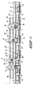
- FIG 1 shows a loading installation in the in stallation according to the invention, while 2, 3, 4 and 5 represent machining tools set up in machining operation stations.
- the machining tool in this case has an X-Y-Z-control.
- the movement in the Y direction is limited to a specific region for each of the tools, as indicated by lines 22, 23 and 24.
- the machining tool 2 is machining wooden article 16, which is on bench 7 and is clamped with the aid of clamping devices 13 and 14.
- the machining tool 3 is machining wooden article 17, which is located on clamping bench 8 and is clamped with the clamping devices drawn there, which in terms of position and function correspond to the above-mentioned clamping devices 13 and 14.
- the clamping devices which correspond to 11 and 12 for clamping bench 6, are actuated in said machining stations in order to contact the wooden article and clamp this, after which the clamping devices 13 and 14 are then removed.
- the clamping benches with the clamping devices 11 and 12 can now be transported so that wooden article 15 comes to lie by machining tool 2 and that wooden article 16 comes to lie by machining tool 3, etc.
- the clamping benches 6, 7, 8 and 9 are first fixed relative to the respective machining operation stations 25, 26, 27 and 28, after which, depending on the machining to be carried out, the clamping devices 11 and 12 are maintained in contact with the wooden article or the stationary clamping devices corresponding to 13 and 14 are applied, after which the clamping devices corresponding to 11 and 12 can be de-coupled.
- a machining operation is first carried out with clamping devices which can be coupled in the coupled position and the station ary clamping devices are then brought to the clamping position and subsequently the clamping devices which can be coupled are de-coupled and moved back to the previous station. A further machining is then carried out in the same station.
- the installation sketched here shows, per clamping plate, two clamping devices 11 and 12, which can be coupled and move with the clamping plate, and also two stationary clamping devices 13 and 14 connected to each machining operation station.
- the number and the shape of the types of clamping devices sketched here can be varied at will and the installation can also be designed such that several identical articles can be clamped per clamping bench.
- FIG. 2 Part of the installation from Figure 1 is shown schematically in Figure 2 and an impression is gained of the system with which the clamping benches are transported. It is indicated in the drawing that the clamping benches are transported horizontally and that clamping benches are transferred from one conveying system to the other at the start and end of the installation.
- the clamping bench 6 can be provided with a wooden article to be machined, the control unit of the total installation being designed such that clamping devices 11 and 12 located at clamping bench 6 can be operated manually independently of the functioning of the remaining part of the installation.
- the wooden articles are removed from the clamps, for example with the aid of a robot or with the clamping bench returned to the line operator for checking or further machining.
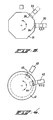
- Figure 3 indicates that, in connection with space-saving, an installation according to the invention can be designed as, for example, a multi-angle drum, the shaft of which is horizontal.
- clamping devices of the two types previously described are located on the surfaces of the multi-angle drum, while it is indicated schematically that wooden articles 34 and 35 can be machined by machining tools 32 and 33, which have an X-Y-Z-control.
- Figure 4 also shows schematically that the wooden articles to be machined can also be located on a disc-shaped support which can be rotated step-wise and on which clamping benches with the two types of clamping devices previously described are located.
- the machining tools 42 and 43 are agin of the X-Y-Z-controlled type.
- clamping bench this term may, with equal meaning, be read as clamping table.
Landscapes
- Engineering & Computer Science (AREA)
- Mechanical Engineering (AREA)
- Life Sciences & Earth Sciences (AREA)
- Wood Science & Technology (AREA)
- Forests & Forestry (AREA)
- Milling, Drilling, And Turning Of Wood (AREA)
- Jigs For Machine Tools (AREA)
Applications Claiming Priority (2)
| Application Number | Priority Date | Filing Date | Title |
|---|---|---|---|
| NL8800814A NL8800814A (nl) | 1988-03-30 | 1988-03-30 | Werkwijze voor het bewerken van houten voorwerpen, inrichting voor het uitvoeren van een dergelijke werkwijze en in een dergelijke inrichting te gebruiken spantafel. |
| NL8800814 | 1988-03-30 |
Publications (1)
| Publication Number | Publication Date |
|---|---|
| EP0335464A1 true EP0335464A1 (fr) | 1989-10-04 |
Family
ID=19852037
Family Applications (1)
| Application Number | Title | Priority Date | Filing Date |
|---|---|---|---|
| EP89200769A Withdrawn EP0335464A1 (fr) | 1988-03-30 | 1989-03-23 | Procédé et dispositif pour travailler des pièces en bois |
Country Status (4)
| Country | Link |
|---|---|
| US (1) | US4944339A (fr) |
| EP (1) | EP0335464A1 (fr) |
| JP (1) | JPH01301301A (fr) |
| NL (1) | NL8800814A (fr) |
Cited By (11)
| Publication number | Priority date | Publication date | Assignee | Title |
|---|---|---|---|---|
| EP0580906A1 (fr) * | 1992-07-28 | 1994-02-02 | Tri-Way Machine Limited | Appareil de transfert guidé avec précision |
| EP0922547A3 (fr) * | 1997-11-28 | 2001-03-14 | IMA Maschinenfabriken Klessmann GmbH | Dispositif pour la fabrication de châssis de fenêtres |
| EP1810802A1 (fr) | 2006-01-20 | 2007-07-25 | SCM GROUP S.p.A. | Machine-outil |
| ITPD20080384A1 (it) * | 2008-12-30 | 2010-06-30 | Essetre Holding S R L | Centro di lavoro per la lavorazione di pannelli in legno e simili |
| ITBO20090640A1 (it) * | 2009-10-02 | 2011-04-03 | Biesse Spa | Metodo e macchina per la lavorazione di componenti di legno o simili per infissi |
| EP2353815A1 (fr) * | 2010-01-29 | 2011-08-10 | Essetre holding SPA | Centre d'usinage pour panneaux d'usinage en bois et similaire |
| EP2295214A3 (fr) * | 2009-09-12 | 2013-01-02 | IMA Klessmann GmbH Holzbearbeitungssysteme | Dispositif destiné au traitement de pièces à usiner |
| ITMI20130727A1 (it) * | 2013-05-03 | 2014-11-04 | T O P S R L | Macchina per la lavorazione di elementi che compongono mobili, complementi di arredo e simili. |
| EP2153954B1 (fr) * | 2008-08-06 | 2015-01-14 | Masterwood S.p.A. | Centre d'usinage automatique de pièces de cadre |
| AT514870A3 (de) * | 2013-09-17 | 2016-05-15 | Scm Group Spa | Anlage zur Bearbeitung von Platten oder Werkstücken aus Holz und Ähnlichem, Bearbeitungsmodul und entsprechende Bearbeitungsverfahren |
| DE102017106329A1 (de) * | 2017-03-23 | 2018-09-27 | Guido Schulte | Bearbeitungsanlage für plattenförmige Werkstücke |
Families Citing this family (11)
| Publication number | Priority date | Publication date | Assignee | Title |
|---|---|---|---|---|
| US5094282A (en) * | 1990-01-25 | 1992-03-10 | Heian Corporated | Lumber processing apparatus |
| US5146962A (en) * | 1991-08-27 | 1992-09-15 | Edward Drees | Woodworking machine |
| US5353910A (en) * | 1992-12-23 | 1994-10-11 | Hem, Inc. | Shuttle vise assembly for a feed table apparatus |
| US5420268A (en) * | 1993-05-27 | 1995-05-30 | Xerox Corporation | Oxytitanium phthalocyanine imaging members and processes thereof |
| JP2906116B2 (ja) * | 1994-11-14 | 1999-06-14 | 忍 大西 | 長尺ワークの順送り自動加工方法及びその装置 |
| US6775893B2 (en) | 1995-06-07 | 2004-08-17 | Sealy Technology Llc | Jigs for assembly of flexible support structures |
| US5862584A (en) * | 1995-10-25 | 1999-01-26 | Manser; Russell D. | Automated apparatus for cutting and notching stock material |
| EP0989923B1 (fr) * | 1997-06-17 | 2003-12-03 | WITZIG & FRANK GmbH | Machine outil a flexibilite elevee |
| US7143676B2 (en) * | 2004-09-07 | 2006-12-05 | Marvel Manufacturing Co., Inc. | Vise carriage and support mechanism |
| US20070267103A1 (en) * | 2006-05-18 | 2007-11-22 | Unique Machine And Tool Co. | Woodworking machine |
| US7857019B2 (en) * | 2008-06-03 | 2010-12-28 | Phillip Freeman Willis | System and method for cutting a profile in a workpiece |
Citations (7)
| Publication number | Priority date | Publication date | Assignee | Title |
|---|---|---|---|---|
| US1577744A (en) * | 1923-12-07 | 1926-03-23 | Fisher Body Corp | Automatic machine for cutting door stiles |
| US2948897A (en) * | 1957-04-19 | 1960-08-16 | Kaywood Corp | Machine for use in manufacturing blind slats and the like |
| US3215175A (en) * | 1963-08-05 | 1965-11-02 | Carl I Hibner | Apparatus for making arcuate molding strips |
| US3295570A (en) * | 1962-10-26 | 1967-01-03 | Zuckermann Komm Ges Wien Fa Ma | Process and machine-tool for longitudinal and transverse machining |
| DE1453209A1 (de) * | 1963-11-22 | 1969-05-29 | Zuckermann Kg Maschf | Anlage zum Bearbeiten von plattenfoermigen,ebenen oder gekruemmten Werkstuecken aus Holz in einem kontinuierlichen Arbeitsablauf |
| FR2481679A1 (fr) * | 1980-04-30 | 1981-11-06 | Durand & Molaire Atel | Transporteur sans fin, a chariots independants, pour le transfert de pieces entre des postes de travail |
| US4410025A (en) * | 1981-03-17 | 1983-10-18 | Paul Sicotte & Fils Ltee | Method and apparatus for making wooden chair seats |
Family Cites Families (7)
| Publication number | Priority date | Publication date | Assignee | Title |
|---|---|---|---|---|
| AT316849B (de) * | 1971-07-23 | 1974-07-25 | Zuckermann Kom Ges Wien Maschf | Taktstraße für die Bearbeitung von Werkstücken aus Holz |
| US3865162A (en) * | 1972-03-17 | 1975-02-11 | Zuckermann Kg Maschf | Apparatus for shaping a wooden workpiece according to a template configuration |
| JPS5115020A (ja) * | 1974-07-23 | 1976-02-06 | Asahi Chemical Ind | Horiesuterukeifukugosenino seizohoho |
| JPS51150200A (en) * | 1975-06-19 | 1976-12-23 | Heian Iron Works | Woodworking milling machine |
| JPS5232198A (en) * | 1975-09-08 | 1977-03-11 | Heian Iron Works | Woodworking milling machine |
| BE859300A (nl) * | 1977-10-03 | 1978-04-03 | Bekaert Eng | Doorvoerfreesmachine voor houten werkstukken |
| JPS6023122U (ja) * | 1983-07-25 | 1985-02-16 | 日立造船株式会社 | 揚土装置 |
-
1988
- 1988-03-30 NL NL8800814A patent/NL8800814A/nl not_active Application Discontinuation
-
1989
- 1989-03-23 EP EP89200769A patent/EP0335464A1/fr not_active Withdrawn
- 1989-03-29 US US07/329,951 patent/US4944339A/en not_active Expired - Fee Related
- 1989-03-30 JP JP1081324A patent/JPH01301301A/ja active Pending
Patent Citations (7)
| Publication number | Priority date | Publication date | Assignee | Title |
|---|---|---|---|---|
| US1577744A (en) * | 1923-12-07 | 1926-03-23 | Fisher Body Corp | Automatic machine for cutting door stiles |
| US2948897A (en) * | 1957-04-19 | 1960-08-16 | Kaywood Corp | Machine for use in manufacturing blind slats and the like |
| US3295570A (en) * | 1962-10-26 | 1967-01-03 | Zuckermann Komm Ges Wien Fa Ma | Process and machine-tool for longitudinal and transverse machining |
| US3215175A (en) * | 1963-08-05 | 1965-11-02 | Carl I Hibner | Apparatus for making arcuate molding strips |
| DE1453209A1 (de) * | 1963-11-22 | 1969-05-29 | Zuckermann Kg Maschf | Anlage zum Bearbeiten von plattenfoermigen,ebenen oder gekruemmten Werkstuecken aus Holz in einem kontinuierlichen Arbeitsablauf |
| FR2481679A1 (fr) * | 1980-04-30 | 1981-11-06 | Durand & Molaire Atel | Transporteur sans fin, a chariots independants, pour le transfert de pieces entre des postes de travail |
| US4410025A (en) * | 1981-03-17 | 1983-10-18 | Paul Sicotte & Fils Ltee | Method and apparatus for making wooden chair seats |
Cited By (14)
| Publication number | Priority date | Publication date | Assignee | Title |
|---|---|---|---|---|
| EP0580906A1 (fr) * | 1992-07-28 | 1994-02-02 | Tri-Way Machine Limited | Appareil de transfert guidé avec précision |
| EP0922547A3 (fr) * | 1997-11-28 | 2001-03-14 | IMA Maschinenfabriken Klessmann GmbH | Dispositif pour la fabrication de châssis de fenêtres |
| EP1810802A1 (fr) | 2006-01-20 | 2007-07-25 | SCM GROUP S.p.A. | Machine-outil |
| EP2153954B1 (fr) * | 2008-08-06 | 2015-01-14 | Masterwood S.p.A. | Centre d'usinage automatique de pièces de cadre |
| ITPD20080384A1 (it) * | 2008-12-30 | 2010-06-30 | Essetre Holding S R L | Centro di lavoro per la lavorazione di pannelli in legno e simili |
| EP2295214A3 (fr) * | 2009-09-12 | 2013-01-02 | IMA Klessmann GmbH Holzbearbeitungssysteme | Dispositif destiné au traitement de pièces à usiner |
| ITBO20090640A1 (it) * | 2009-10-02 | 2011-04-03 | Biesse Spa | Metodo e macchina per la lavorazione di componenti di legno o simili per infissi |
| EP2305440A1 (fr) * | 2009-10-02 | 2011-04-06 | BIESSE S.p.A. | Procédé et appareil pour le traitement de composants en bois. |
| EP2353815A1 (fr) * | 2010-01-29 | 2011-08-10 | Essetre holding SPA | Centre d'usinage pour panneaux d'usinage en bois et similaire |
| WO2014177922A1 (fr) * | 2013-05-03 | 2014-11-06 | T.O.P. S.R.L. | Appareil de traitement d'éléments de mobilier, des ameublements et articles similaires |
| ITMI20130727A1 (it) * | 2013-05-03 | 2014-11-04 | T O P S R L | Macchina per la lavorazione di elementi che compongono mobili, complementi di arredo e simili. |
| AT514870A3 (de) * | 2013-09-17 | 2016-05-15 | Scm Group Spa | Anlage zur Bearbeitung von Platten oder Werkstücken aus Holz und Ähnlichem, Bearbeitungsmodul und entsprechende Bearbeitungsverfahren |
| AT514870B1 (de) * | 2013-09-17 | 2017-03-15 | Scm Group Spa | Anlage zur Bearbeitung von Platten oder Werkstücken aus Holz und Ähnlichem, Bearbeitungsmodul und entsprechende Bearbeitungsverfahren |
| DE102017106329A1 (de) * | 2017-03-23 | 2018-09-27 | Guido Schulte | Bearbeitungsanlage für plattenförmige Werkstücke |
Also Published As
| Publication number | Publication date |
|---|---|
| NL8800814A (nl) | 1989-10-16 |
| US4944339A (en) | 1990-07-31 |
| JPH01301301A (ja) | 1989-12-05 |
Similar Documents
| Publication | Publication Date | Title |
|---|---|---|
| EP0335464A1 (fr) | Procédé et dispositif pour travailler des pièces en bois | |
| JP7360537B2 (ja) | 材料自動供給排出加工システム | |
| KR100941334B1 (ko) | 터릿 툴 및 기계가공 툴 | |
| KR100241837B1 (ko) | 다수의 스핀들을 구비한 공작 기계 | |
| US5096346A (en) | Side face machining apparatus | |
| EP1250976B1 (fr) | Machine-outil pour l'usinage de pièces allongées | |
| CN101198440A (zh) | 用于灵活加工工件的生产线 | |
| JPS6159867B2 (fr) | ||
| CN113927438A (zh) | 丝锥加工中心及加工方法 | |
| CN112140250B (zh) | 一种木器加工装置及加工方法 | |
| US6233810B1 (en) | Apparatus for machining workpieces | |
| EP2117790B1 (fr) | Centre d'usinage | |
| US4410025A (en) | Method and apparatus for making wooden chair seats | |
| JPH071204A (ja) | 立旋盤 | |
| JPS59129601A (ja) | 工作機械 | |
| EP2846967B1 (fr) | Centre d'usinage destiné un usinage multiple | |
| US4621408A (en) | Sequential phase convertible machine | |
| EP0121438A1 (fr) | Système de fabrication flexible et méthode | |
| CN213593108U (zh) | 一种木器加工装置 | |
| US5187846A (en) | Pallet changer | |
| CN112454012A (zh) | 一种小型工件加工系统 | |
| CN211662242U (zh) | 一种加工效率高的数控木工机床 | |
| CN211306617U (zh) | 一种多功能数控木工机床 | |
| JPH0796432A (ja) | シャルピー試験片加工用マシニングセンタ及び加工装置 | |
| US4727982A (en) | Workpiece transfer apparatus |
Legal Events
| Date | Code | Title | Description |
|---|---|---|---|
| PUAI | Public reference made under article 153(3) epc to a published international application that has entered the european phase |
Free format text: ORIGINAL CODE: 0009012 |
|
| AK | Designated contracting states |
Kind code of ref document: A1 Designated state(s): AT BE CH DE ES FR GB GR IT LI LU NL SE |
|
| 17P | Request for examination filed |
Effective date: 19891020 |
|
| 17Q | First examination report despatched |
Effective date: 19920214 |
|
| STAA | Information on the status of an ep patent application or granted ep patent |
Free format text: STATUS: THE APPLICATION IS DEEMED TO BE WITHDRAWN |
|
| 18D | Application deemed to be withdrawn |
Effective date: 19930408 |