EP0335687B1 - Construction d'un embrayage hydraulique - Google Patents
Construction d'un embrayage hydraulique Download PDFInfo
- Publication number
- EP0335687B1 EP0335687B1 EP19890303103 EP89303103A EP0335687B1 EP 0335687 B1 EP0335687 B1 EP 0335687B1 EP 19890303103 EP19890303103 EP 19890303103 EP 89303103 A EP89303103 A EP 89303103A EP 0335687 B1 EP0335687 B1 EP 0335687B1
- Authority
- EP
- European Patent Office
- Prior art keywords
- piston
- clutch
- hydraulic
- hydraulic pressure
- assisting
- Prior art date
- Legal status (The legal status is an assumption and is not a legal conclusion. Google has not performed a legal analysis and makes no representation as to the accuracy of the status listed.)
- Expired
Links
- 238000010276 construction Methods 0.000 title claims description 10
- 239000012858 resilient material Substances 0.000 claims description 3
- 230000005540 biological transmission Effects 0.000 description 13
- 230000000717 retained effect Effects 0.000 description 2
- 230000009977 dual effect Effects 0.000 description 1
- 230000008030 elimination Effects 0.000 description 1
- 238000003379 elimination reaction Methods 0.000 description 1
- 239000000463 material Substances 0.000 description 1
- 238000007789 sealing Methods 0.000 description 1
Images


Classifications
-
- F—MECHANICAL ENGINEERING; LIGHTING; HEATING; WEAPONS; BLASTING
- F16—ENGINEERING ELEMENTS AND UNITS; GENERAL MEASURES FOR PRODUCING AND MAINTAINING EFFECTIVE FUNCTIONING OF MACHINES OR INSTALLATIONS; THERMAL INSULATION IN GENERAL
- F16D—COUPLINGS FOR TRANSMITTING ROTATION; CLUTCHES; BRAKES
- F16D13/00—Friction clutches
- F16D13/58—Details
- F16D13/583—Diaphragm-springs, e.g. Belleville
-
- F—MECHANICAL ENGINEERING; LIGHTING; HEATING; WEAPONS; BLASTING
- F16—ENGINEERING ELEMENTS AND UNITS; GENERAL MEASURES FOR PRODUCING AND MAINTAINING EFFECTIVE FUNCTIONING OF MACHINES OR INSTALLATIONS; THERMAL INSULATION IN GENERAL
- F16D—COUPLINGS FOR TRANSMITTING ROTATION; CLUTCHES; BRAKES
- F16D25/00—Fluid-actuated clutches
- F16D25/06—Fluid-actuated clutches in which the fluid actuates a piston incorporated in, i.e. rotating with the clutch
- F16D25/062—Fluid-actuated clutches in which the fluid actuates a piston incorporated in, i.e. rotating with the clutch the clutch having friction surfaces
- F16D25/063—Fluid-actuated clutches in which the fluid actuates a piston incorporated in, i.e. rotating with the clutch the clutch having friction surfaces with clutch members exclusively moving axially
- F16D25/0635—Fluid-actuated clutches in which the fluid actuates a piston incorporated in, i.e. rotating with the clutch the clutch having friction surfaces with clutch members exclusively moving axially with flat friction surfaces, e.g. discs
- F16D25/0638—Fluid-actuated clutches in which the fluid actuates a piston incorporated in, i.e. rotating with the clutch the clutch having friction surfaces with clutch members exclusively moving axially with flat friction surfaces, e.g. discs with more than two discs, e.g. multiple lamellae
Definitions
- the present invention relates to a hydraulic cluth construction according to the preamble of Claim 1. Hydraulically operated clutch constructions of that kind are for use in automatic transmissions or the like.
- Hydraulic clutches have been used in automotive automatic transmissions.
- Such a hydraulic clutch comprises a clutch drum having a hydraulic pressure chamber, a piston movably fitted in the clutch drum in covering relation to the hydraulic pressure chamber, and a pressure plate, a drive plate, and a driven plate which are successively disposed in confronting relation to a surface of the piston remote from its surface facing the hydraulic pressure chamber.
- Another proposed hydraulic clutch includes a diaphragm spring disposed between the piston and the pressure plate, the diaphragm spring having a radially inner end pressable by the piston and a radially outer end held against the clutch drum.
- the pressure plate has a projection held in abutment against the diaphragm spring between the radially inner and outer ends thereof.
- the diaphragm spring is thus caused to act as a lever with the radially outer end serving as its fulcrum.
- the force applied by the piston is boosted by the lever through the projections and transmitted to the pressure plate.
- a hydraulic clutch of this construction is disclosed in Japanese Laid-Open Patent Publication JP-A-56-164228, for example.
- the piston has a boost release projection corresponding to the projection on the pressure plate.
- the boost release projections When the piston is moved a distance greater than a predetermined stroke, the boost release projections are brought into engagement with the diaphragm spring to release the diaphragm spring from the boosting action, thereby preventing a high load from being applied to the diaphragm spring.
- the diaphragm spring which serves as a lever is subject to a high load and a high stress, it can be used only in a limited pressure range in view of the available mechanical strength and durability of the diaphragm spring.
- the hydraulic clutch is small in size and the diaphragm spring is small in diameter, with a resultant higher hydraulic pressure for a desired clutch capability, sufficient mechanical strength and durability cannot be given to the diaphragm spring.
- the stroke of the piston For transmitting the force of the piston via the diaphragm spring to the pressure plate, the stroke of the piston must allow for the flexing of the diaphragm spring. Inasmuch as the piston stroke is increased, an extra axial space is needed in the clutch to accommodate the piston stroke.
- the load on the diaphragm spring is prevented from being excessively high.
- the boosting ability of the diaphragm spring is available only until the boost release project-ion engages the diaphragm spring. Consequently, the maximum capacity of the hydraulic clutch remains the same as it would be if there were no diaphragm spring in the clutch.
- US-A-2806 568 forming the preamble of Claim 1 discloses a hydraulique clutch having a lever to apply a boosted force from the piston to the pressure plate, and having a return spring for urging the piston back into the hydraulic pressure chamber. However, additional components are required to hold the lever in engagement with the piston.
- a hydraulic clutch construction comprising: a clutch drum having a hydraulic pressure chamber defined therein; a piston movably fitted in said clutch drum in covering relation to said hydraulic pressure chamber; a pressure plate disposed in confronting relation to a surface of said piston remotely from said hydraulic pressure chamber, and having a projection; interleaved drive and driven plates disposed in confronting relation to a surface of said pressure plate remotely from said piston, and engageable with each other by said pressure plate pressed by said piston moved in response to a hydraulic pressure supplied to said hydraulic pressure chamber; a return spring for urging said piston back into said hydraulic pressure chamber; and an assisting member disposed between said piston and said pressure plate and comprising an annular array of rigid assisting levers and a retaining plate holding said assisting levers together, said assisting member having a radially inner end pressableby said piston, a radially outer end held in engagement with said clutch drum, and a radially intermediate region engageable with said projection of said pressure plate, the arrangement being such that each said assisting assisting
- the levers preferably engage directly the projection of the pressure plate.
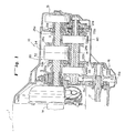
- Fig.1 shows an automotive automatic transmission having hydraulic clutches according to the present invention.
- the transmission generally designated by the reference numeral 10, is positioned at the output end of an output shaft 1a of an engine 1 to which a torque converter 12 is coupled.
- the torque converter 12 has an output shaft connected to an input shaft 13 of the transmission 10 for transmitting output power from the engine 1 through the torque converter 12 to the transmission input shaft 13.
- the transmission 10 includes a countershaft 14 extending parallel to the input shaft 13, and a transmission mechanism 20 disposed between the input shaft 13 and the countershaft 14.
- the transmission mechanism 20 has a drive assembly disposed on the countershaft 13 and a driven assembly disposed on the countershaft 14, and includes intermeshing gears 21a, 21b for a first-speed gear position, intermeshing gears 22a, 22b for a second-speed gear position, intermeshing gears 23a, 23b for a third-speed gear position, intermeshing gears 24a, 24b for a fourth-speed gear position, and intermeshing gears 25a, 25b for a reverse gear position.
- the reverse gears 25a, 25b mesh with each other through a reverse idler gear (not shown) for reversing the direction of rotation.
- the first-speed drive gear 21 a, the second-speed drive gear 22a, the third-speed driven gear 23b, the fourth-speed drive gear 24a, and the reverse driven gear 25b may be rotatably mounted on the input shaft 13 or the countershaft 14, as the case may be, and the other gears may be fixedly mounted on the input shaft 13 or countershaft 14.
- the gears rotatably mounted on the shaft are associated respectively with hydraulic clutches 31, 32, 33, 34, and 40. By selectively engaging these five hydraulic clutches, one of the rotatably mounted gears is coupled to the shaft on which it is mounted to transmit engine output power through the gear and the gear meshing therewith.
- the hydraulic clutch 40 associated with the reverse gears is of a construction according to the present invention.
- the hydraulic clutch 40 and the hydraulic clutch 34 associated with the fourth-speed gears will be described with reference to Fig. 2.
- the hydraulic clutch 34 which is of a conventional structure will first be described briefly below.
- the hydraulic clutch 34 has a clutch drum 34a joined back-to-back to the clutch drum of the hydraulic clutch 32 and fixedly mounted on the input shaft 13, and a piston 34b axially movably fitted in the clutch drum 34a in covering relation to a hydraulic pressure chamber 34c defined in the clutch drum 34a.
- the piston 34b is normally urged at its radially inner end to move into the hydraulic pressure chamber 34c (i.e., to the left) under the bias of a return spring 34f.
- the piston 34b is moved to the left as shown under the resiliency of the return spring 34f.
- the piston 34b has a radially outer end confronting a plurality of interleaved clutch plates 34d and clutch discs 34e.
- the clutch plates 34d engage the clutch drum 34a, whereas the clutch discs 34e engage clutch splines 24c integral with the fourth-speed drive gear 24a.
- the clutch plates 34d and the clutch discs 34e are retained in the clutch drum 34a by an end plate 34g and a snap ring 34h.
- the hydraulic clutch 40 of the invention has a clutch drum 41 fixedly mounted on the countershaft 14 and a piston 41 axially movably fitted on the clutch drum 41 in covering relation to a hydraulic pressure chamber 43 defined in the clutch drum 41.
- the piston 42 is normally urged at its radially inner end to move into the hydraulic pressure chamber 43 (i.e., to the left) under the bias of a return spring 50.
- the piston 42 is moved to the left as shown under the resiliency of the return spring 50.
- the hydraulic clutch 40 has a plurality of interleaved clutch plates 46 and clutch discs 47 which are retained in the clutch drum 41 by an end plate 48a and a snap ring 48b.
- the clutch plates 46 engage the clutch drum 41, while the clutch discs 47 engage clutch splines 25d integral with the reverse driven gear 25b.
- a pressure plate 45 is disposed on a piston side of the leftmost clutch disc 47 which is closest to the piston 42, with a slightly conical disc-shaped assisting member 44 interposed between the pressure plate 45 and the piston 42.
- the assisting member 44 is illustrated in detail in Figs. 3A and 3B. As shown in Figs. 3A and 3B, the assisting member 44 comprises a slightly conical, annular array of assisting levers 44a (twelve in the illustrated embodiment) which are held together by a retaining plate 44b shown in Figs. 4A and 4B.
- the radially inner ends of the assisting levers 44a abut against the piston 42 through a support ring 49a, and the radially outer ends of the assisting levers 44a are sandwiched between a support ring 49b and a snap ring 49c.
- the pressure plate 45 has a projection 45a projecting axially toward the assisting member 44 and engageable with the assisting member 44 at a position radially intermediate between its radially inner and outer ends.
- each assisting lever is in force-transmitting engagement with the clutch drum at its radially outer end and is in force-transmitting engagement with the piston at its radially inner end and the retaining plate is in the form of a conical ring of such inner and outer diameters that it extends to only intermediate portions of the levers and is connected to the levers in the intermediate portions.
- the levers engage directly the projection 45a of the pressure plate.
- the force from the pressure plate 45 is larger than the force from the piston 42 by an amount commensurate with the lever ratio of the assisting member 44.
- the torque transmitting capability of the reverse hydraulic clutch 40 is thus increased without increasing the hydraulic pressure in the hydraulic pressure chamber 43.
- a large torque transmitting requirement of the hydraulic clutch 40 can therefore be met without increasing the size of the hydraulic clutch 40.
- the assisting lever 44a is made of a rigid material and does not flex to an appreciable extent, so that the stroke of the piston 42 is not increased.
- the retaining plate 44b of the assisting member 44 serves to hold the assisting levers 44a together.
- the retaining plate 44b is made of a resilient material so as to serve as a Belleville spring for urging the piston 42 into the hydraulic pressure chamber 43.
- the retaining plate 44b thus constructed is used to assist the spring force of the return spring 50.
- the radially inner end of the assisting member is pushed by the piston and the radially outer end of the assisting member is borne by the clutch drum, with the intermediate region of the assisting member being disposed for pressing the pressure plate.
- the assisting member thus serves as a lever with the radially outer end as the fulcrum, the radially inner end receiving the applied force, and the intermediate region applying the boosted force to the pressure plate.
- the force applied from the piston is thus boosted by the assisting member and then transmitted to the pressure plate.
- the torque transmitting capability of the reverse hydraulic clutch is thus increased without increasing the hydraulic pressure in the hydraulic pressure chamber to exert a force to the piston. That is, the size of the hydraulic clutch can be reduced without lowering the capacity of the hydraulic clutch.
- the assisting member comprises a rigid member, it does not appreciably flex as compared with the conventional diaphragm spring used as a lever, so the piston has a minimum stroke loss. Consequently, the axial dimension of the hydraulic clutch required to accommodate the piston stroke is reduced, making the hydraulic clutch compact.
Landscapes
- Engineering & Computer Science (AREA)
- General Engineering & Computer Science (AREA)
- Mechanical Engineering (AREA)
- Hydraulic Clutches, Magnetic Clutches, Fluid Clutches, And Fluid Joints (AREA)
- Mechanical Operated Clutches (AREA)
- Gear-Shifting Mechanisms (AREA)
Claims (3)
- Construction d'embrayage hydraulique (40) comprenant :
un tambour (41) d'embrayage ayant une chambre de pression hydraulique délimitée à l'intérieur,
un piston (42) monté dans le tambour d'embrayage (41) afin qu'il soit mobile et qu'il recouvre la chambre de pression hydraulique (43),
un plateau de pression (45) disposé en face d'une surface du piston (42) du côté opposé à la chambre de pression hydraulique (43) et ayant une saillie (45a),
des plateaux menants et menés (46, 47) qui sont imbriqués et sont en face d'une surface du plateau de pression (45) qui est opposée au piston (42) et qui sont destinés à être mis mutuellement en contact par le plateau de pression (45) lorsque celui-ci est repoussé par le piston (42) déplacé sous l'effet d'un fluide hydraulique sous pression transmis à la chambre de pression hydraulique (43),
un ressort de rappel (50) destiné à rappeler le piston (42) dans la chambre de pression hydraulique (43), et
un organe d'assistance (44) disposé entre le piston (42) et le plateau de pression (45) et comprenant un ensemble annulaire de leviers rigides d'assistance (44a) et une plaque de retenue (44b) qui maintient ensemble les leviers d'assistance, l'organe d'assistance (44) ayant une extrémité radialement interne qui peut être repoussée par le piston (42), une extrémité radialement externe maintenue au contact du tambour d'embrayage (41), et une région radialement intermédiaire destinée à venir au contact de la saillie (45a) du plateau de pression (45), la disposition étant telle que chaque levier d'asssatance (44a) est utilisé comme un levier ayant l'extrémité radialement externe comme pivot pour la multiplication de la force appliquée par le piston (42) et la transmission de la force multipliée au plateau de pression (45),
chaque levier d'assistance (44a) coopérant pour la transmission des forces avec le tambour d'embrayage (41) à son extrémité radialement externe et coopérant pour la transmissaion des forces avec le piston (42) à son extrémité radialement interne, caractérisée en ce que la plaque de retenue (44b) est sous forme d'une bague conique ayant des diamètres interne et externe tels qu'elle s'étend seulement jusqu'à des parties intermédiaires des leviers (44a) et est raccordée aux leviers dans ces parties intermédiaires, et en ce que
la plaque de retenue (44b) est formée d'un matériau élastique afin qu'elle joue le rôle d'une rondelle Belleville pour le rappel du piston (42) vers la chambre de pression hydraulique (43). - Construction d'embrayage hydraulique (40) selon la revendication 1, dans laquelle les leviers (44a) sont directement au contact de la saillie (45a) du plateau de pression (45).
- Construction d'embrayage hydraulique (40) selon la revendication 1 ou 2, dans laquelle l'extrémité radialement externe de l'organe d'assistance (44) est prise en sandwich entre une bague de support (49b) et une bague élastique (49c) afin que l'extrémité radialement externe soit maintenue au contact du tambour d'embrayage (41).
Applications Claiming Priority (2)
| Application Number | Priority Date | Filing Date | Title |
|---|---|---|---|
| JP75658/88 | 1988-03-29 | ||
| JP63075658A JPH0745888B2 (ja) | 1988-03-29 | 1988-03-29 | 油圧クラッチ構造 |
Publications (2)
| Publication Number | Publication Date |
|---|---|
| EP0335687A1 EP0335687A1 (fr) | 1989-10-04 |
| EP0335687B1 true EP0335687B1 (fr) | 1992-09-09 |
Family
ID=13582552
Family Applications (1)
| Application Number | Title | Priority Date | Filing Date |
|---|---|---|---|
| EP19890303103 Expired EP0335687B1 (fr) | 1988-03-29 | 1989-03-29 | Construction d'un embrayage hydraulique |
Country Status (4)
| Country | Link |
|---|---|
| EP (1) | EP0335687B1 (fr) |
| JP (1) | JPH0745888B2 (fr) |
| CA (1) | CA1312297C (fr) |
| DE (1) | DE68902759T2 (fr) |
Cited By (1)
| Publication number | Priority date | Publication date | Assignee | Title |
|---|---|---|---|---|
| US10927901B2 (en) | 2016-07-07 | 2021-02-23 | Unipres Corporation | Wet multi-plate clutch |
Families Citing this family (7)
| Publication number | Priority date | Publication date | Assignee | Title |
|---|---|---|---|---|
| ES2119667B1 (es) * | 1994-12-24 | 1999-04-01 | Fichtel & Sachs Ag | Embrague de friccion con muelle auxiliar para asistir a la fuerza de desembragado. |
| JP2884483B2 (ja) * | 1995-08-29 | 1999-04-19 | 本田技研工業株式会社 | 湿式多板クラッチの潤滑構造 |
| IT238205Y1 (it) * | 1997-04-30 | 2000-10-16 | Cavalli Dante & Walter Omc | Giunto limitatore di coppia azionato da un fluido in pressione |
| SE9801025L (sv) * | 1998-03-26 | 1999-09-27 | Lysholm Techn Ab | Kopplingsanordning av friktionstyp |
| JP2002106598A (ja) * | 2000-09-27 | 2002-04-10 | Nsk Warner Kk | 摩擦係合装置 |
| BRPI0613052A8 (pt) * | 2005-07-15 | 2016-12-13 | Luk Lamellen & Kupplungsbau | Disposição de alavanca para uma embreagem de fricção, bem como, embreagem de fricção com uma disposição de alavanca desse tipo |
| FR3142519B1 (fr) * | 2022-11-25 | 2026-03-20 | Valeo Embrayages | Embrayage humide pour engin motorise |
Family Cites Families (8)
| Publication number | Priority date | Publication date | Assignee | Title |
|---|---|---|---|---|
| FR829074A (fr) * | 1937-11-15 | 1938-06-10 | Embrayeur à pression d'huile accordant la roue libre | |
| US2806568A (en) * | 1955-08-22 | 1957-09-17 | Int Harvester Co | Clutch lever structure |
| US3013792A (en) * | 1960-04-28 | 1961-12-19 | Fichtel & Sachs Ag | Diaphragm spring arrangement |
| DE1455884A1 (de) * | 1965-06-10 | 1969-06-12 | Ringspann Maurer Kg A | Ausrueckbare Reibungskupplung insbesondere fuer Kraftfahrzeuge |
| JPS4520091Y1 (fr) * | 1967-04-01 | 1970-08-13 | ||
| DE3024196A1 (de) * | 1980-06-27 | 1982-01-14 | Volkswagenwerk Ag, 3180 Wolfsburg | Vorrichtung zur hebelverstaerkenden kraftuebertragung |
| DE3321822A1 (de) * | 1983-06-16 | 1984-12-20 | LuK Lamellen und Kupplungsbau GmbH, 7580 Bühl | Kreisfoermiges bauteil |
| AT379665B (de) * | 1983-06-29 | 1986-02-10 | Enfo Grundlagen Forschungs Ag | Hebelscheibe zum uebertragen von stellkraeften |
-
1988
- 1988-03-29 JP JP63075658A patent/JPH0745888B2/ja not_active Expired - Lifetime
-
1989
- 1989-03-29 CA CA 594974 patent/CA1312297C/fr not_active Expired - Fee Related
- 1989-03-29 DE DE1989602759 patent/DE68902759T2/de not_active Expired - Fee Related
- 1989-03-29 EP EP19890303103 patent/EP0335687B1/fr not_active Expired
Cited By (1)
| Publication number | Priority date | Publication date | Assignee | Title |
|---|---|---|---|---|
| US10927901B2 (en) | 2016-07-07 | 2021-02-23 | Unipres Corporation | Wet multi-plate clutch |
Also Published As
| Publication number | Publication date |
|---|---|
| CA1312297C (fr) | 1993-01-05 |
| DE68902759D1 (de) | 1992-10-15 |
| EP0335687A1 (fr) | 1989-10-04 |
| JPH01247827A (ja) | 1989-10-03 |
| JPH0745888B2 (ja) | 1995-05-17 |
| DE68902759T2 (de) | 1993-02-04 |
Similar Documents
| Publication | Publication Date | Title |
|---|---|---|
| EP0640773B1 (fr) | Dispositif d'engagement à friction pour une transmission automatique | |
| US4966267A (en) | Ball screw actuated clutch combination | |
| US6543597B2 (en) | Clutch device for an automatic transmission | |
| US5103953A (en) | Hydraulic clutch construction | |
| EP0335687B1 (fr) | Construction d'un embrayage hydraulique | |
| JP3097079B2 (ja) | 自動変速機の変速用摩擦係合装置 | |
| EP0810393B1 (fr) | Transmission automatique de véhicule avec dispositif de freinage pour marche arrière | |
| EP0686790A1 (fr) | Mécanisme de commande d'engagement pour un dispositif de transmission de couple | |
| JPH0477180B2 (fr) | ||
| US20050155826A1 (en) | Friction engaging device | |
| US5480014A (en) | Double clutch arrangement | |
| US3776337A (en) | Dry-disc friction clutch | |
| EP3722632B1 (fr) | Embrayage à friction | |
| KR100907321B1 (ko) | 클러치 플레이트, 이를 구비한 클러치 및 그 클러치를구비한 자동변속기 | |
| US4697677A (en) | Motor vehicle clutch for a mechanical, multiple-speed automatic transmission | |
| GB2122710A (en) | Actuation system for transmission clutch providing engagement pressure controllable according to clutch slip speed | |
| JP2001099189A (ja) | 湿式クラッチの潤滑構造 | |
| US3782216A (en) | Speed change control system for automatic transmission | |
| JPH03537B2 (fr) | ||
| JP3362728B2 (ja) | 変速機の変速用摩擦係合装置 | |
| JPS638339B2 (fr) | ||
| US5950490A (en) | Multi-clutched transmission system | |
| JP2001280368A (ja) | 多板式摩擦係合装置 | |
| KR200191955Y1 (ko) | 수동변속기용 클러치 구조 | |
| JPH0617846A (ja) | 油圧クラッチ装置 |
Legal Events
| Date | Code | Title | Description |
|---|---|---|---|
| PUAI | Public reference made under article 153(3) epc to a published international application that has entered the european phase |
Free format text: ORIGINAL CODE: 0009012 |
|
| AK | Designated contracting states |
Kind code of ref document: A1 Designated state(s): DE FR GB IT |
|
| 17P | Request for examination filed |
Effective date: 19891229 |
|
| 17Q | First examination report despatched |
Effective date: 19900405 |
|
| GRAA | (expected) grant |
Free format text: ORIGINAL CODE: 0009210 |
|
| AK | Designated contracting states |
Kind code of ref document: B1 Designated state(s): DE FR GB IT |
|
| REF | Corresponds to: |
Ref document number: 68902759 Country of ref document: DE Date of ref document: 19921015 |
|
| ET | Fr: translation filed | ||
| ITF | It: translation for a ep patent filed | ||
| PGFP | Annual fee paid to national office [announced via postgrant information from national office to epo] |
Ref country code: FR Payment date: 19930317 Year of fee payment: 5 |
|
| PLBE | No opposition filed within time limit |
Free format text: ORIGINAL CODE: 0009261 |
|
| STAA | Information on the status of an ep patent application or granted ep patent |
Free format text: STATUS: NO OPPOSITION FILED WITHIN TIME LIMIT |
|
| 26N | No opposition filed | ||
| PG25 | Lapsed in a contracting state [announced via postgrant information from national office to epo] |
Ref country code: FR Effective date: 19941130 |
|
| REG | Reference to a national code |
Ref country code: FR Ref legal event code: ST |
|
| PGFP | Annual fee paid to national office [announced via postgrant information from national office to epo] |
Ref country code: GB Payment date: 19980326 Year of fee payment: 10 |
|
| PG25 | Lapsed in a contracting state [announced via postgrant information from national office to epo] |
Ref country code: GB Free format text: LAPSE BECAUSE OF NON-PAYMENT OF DUE FEES Effective date: 19990329 |
|
| GBPC | Gb: european patent ceased through non-payment of renewal fee |
Effective date: 19990329 |
|
| PG25 | Lapsed in a contracting state [announced via postgrant information from national office to epo] |
Ref country code: IT Free format text: LAPSE BECAUSE OF NON-PAYMENT OF DUE FEES;WARNING: LAPSES OF ITALIAN PATENTS WITH EFFECTIVE DATE BEFORE 2007 MAY HAVE OCCURRED AT ANY TIME BEFORE 2007. THE CORRECT EFFECTIVE DATE MAY BE DIFFERENT FROM THE ONE RECORDED. Effective date: 20050329 |
|
| PGFP | Annual fee paid to national office [announced via postgrant information from national office to epo] |
Ref country code: DE Payment date: 20060228 Year of fee payment: 18 |
|
| PG25 | Lapsed in a contracting state [announced via postgrant information from national office to epo] |
Ref country code: DE Free format text: LAPSE BECAUSE OF NON-PAYMENT OF DUE FEES Effective date: 20071002 |