EP0336006A2 - Traversée de mur - Google Patents
Traversée de mur Download PDFInfo
- Publication number
- EP0336006A2 EP0336006A2 EP88114175A EP88114175A EP0336006A2 EP 0336006 A2 EP0336006 A2 EP 0336006A2 EP 88114175 A EP88114175 A EP 88114175A EP 88114175 A EP88114175 A EP 88114175A EP 0336006 A2 EP0336006 A2 EP 0336006A2
- Authority
- EP
- European Patent Office
- Prior art keywords
- flange
- casing
- wall
- packing
- traction means
- Prior art date
- Legal status (The legal status is an assumption and is not a legal conclusion. Google has not performed a legal analysis and makes no representation as to the accuracy of the status listed.)
- Withdrawn
Links
Images
Classifications
-
- H—ELECTRICITY
- H02—GENERATION; CONVERSION OR DISTRIBUTION OF ELECTRIC POWER
- H02G—INSTALLATION OF ELECTRIC CABLES OR LINES, OR OF COMBINED OPTICAL AND ELECTRIC CABLES OR LINES
- H02G3/00—Installations of electric cables or lines or protective tubing therefor in or on buildings, equivalent structures or vehicles
- H02G3/22—Installations of cables or lines through walls, floors or ceilings, e.g. into buildings
Definitions
- the invention relates to a wall bushing for lines, such as cables, pipes or the like, for insertion into a wall opening, with a casing pipe penetrating the wall opening, a packing for filling the annular space between the casing pipe and the wall opening and with two axially on both sides of the packing flanges seated on the casing, of which one flange is arranged outside the wall opening and set up for sealing against the outside of the wall and the other flange for the axial pressing of the packing is arranged displaceably within the wall opening and is supported against the axial pressure of the packing, for which purpose between the latter
- a locking device is provided for the flange and the casing, which only allows displacements of the flange on the casing in the direction of the packing, but blocks the flange against displacement in the opposite direction.
- Wall bushings of this type are known from the patent application DE 37 31 583, which does not belong to the previously published prior art. With them, the inner flange is under the force of a spring that presses the flange against the packing so that the packing is compressed in the breakthrough of the wall and the casing against the reveal of the wall breakthrough seals. To do this, unlock the initially tensioned spring so that it can relax and act on the pack.
- this unlocking is carried out in such a way that a packing ring on the casing, which closes the flange towards the flange, is held in a detent seat against the force of the spring, from which the packing ring can only be released when it is spread out, with what A clamping nut provided on the outside in front of the outer flange is possible, which can be screwed into an external thread provided on the casing.
- a disadvantage of this embodiment is the fact that when the clamping nut is screwed on it is not recognizable from the outside whether the packing ring has really unlocked the inner flange and thus the spring and the spring has relaxed accordingly, that is to say the pack has been sufficiently compressed.
- the invention has for its object to provide a wall bushing of the type mentioned in such a way that the pack can be compressed as desired in a precisely controllable manner and with respect to the scope.
- flange located within the wall opening is connected to a traction means which is sealed between the casing on the one hand and the packing and the outer flange on the other hand and is axially movably guided to the outside and on the outside in front of the outside Flange is accessible.
- the inner flange By pulling manually on the externally accessible traction means, the inner flange can be moved against the pack and the pack can be compressed, the path by which and the force with which the compression takes place, if desired, precisely via the traction path and the Traction of the traction device can be measured and controlled.
- the wall bushing according to the invention is of a considerably simpler construction, since the spring and the unlocking device for the spring are dispensed with.
- the traction means is preferably a band which lies flat against the casing. If the tape is thin, for example made of tear-resistant plastic, it does not wear much on the casing and does not impair the sealing effect of the pack.
- a particularly simple and safe handling of the traction device results if, according to a further proposal of the invention, the traction device is guided in a loop, the two traction device ends being connected to the flange and the loop apex lying in front of the outer flange.
- the ends of the traction means are expediently connected to the inner flange at diametrically opposite locations and run diametrically opposite one another axially on the casing.
- the traction means is held in a detent seat on the inner flange and the detent seat is released and the traction means is released when the tractive force of the traction means exceeds a predetermined size.
- the traction means has a predetermined breaking point in front of the inner flange, which breaks when the tractive force of the traction means exceeds a predetermined size. In any case, it is achieved that the traction device can be completely pulled out of the wall duct after releasing it from the resting seat or tearing the predetermined breaking point before the packing pre-compressed with the aid of the inner flange is finally clamped from the outside.
- a preferred embodiment is characterized in that the casing has a longitudinal groove on the outside in the area of the external thread in which the traction means runs.
- the traction device is expediently adapted to the profile cross section of the longitudinal groove and fills the groove cross section.
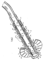
- the wall bushing shown in the drawing for lines not shown, such as cables, pipes or the like, has a casing 1 which is inserted into a wall opening of a wall, not shown in the drawing, preferably designed as a hole.
- the wall duct has a packing 2 filling the annular space between the casing 1 and the reveal of the wall opening and two flanges 3, 4 on both sides of this packing 2 on the outside of the casing 1.
- the flange 3 on the left in the drawing is for sealing against the outside of the wall is set up, for which he has a cross-section of the wall breakthrough radially everywhere and is coated on its side facing the wall with an adhesive or self-sealing sealant 6, which seals the surface of the wall, for example a sealing paint provided there or can connect a waterproofing membrane in a watertight and gas-tight manner.
- the flange 3 is arranged longitudinally displaceably on the casing 1 and on a Axially supported clamping nut 7, which can be screwed into an external thread 8 provided on the casing tube 1 and extending from the left tube end.
- the other flange 4 on the right in the drawing serves to axially compress the packing 2 within the wall opening and can be displaced in the wall opening at least over part of the opening length, but it is always against the axial pressure of the packing 2 in a manner to be described on the casing 1 is supported.
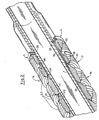
- the packing 2 consists of a series of packing rings 2.2 which can be expanded in diameter and which are supported against one another by means of coaxial conical surfaces 11 with a cone angle which avoids self-locking and which, when the packing 2 is pressed together, axially collapse on the conical surfaces and thereby expand radially.
- the conical surfaces 11 each end at their larger diameter end in an annular shoulder 12 projecting radially outwards beyond the conical surface, against which they come to rest when they have completely pushed together in their conical surfaces 11. So that they can not slip in the ring shoulders 12 from each other, the ring shoulders of adjacent packing rings are set up for radial positive engagement with each other, which is achieved in the exemplary embodiment in that the ring shoulder on the cone outer surface undercut dovetail and the ring shoulder on the cone inner surface with one in Undercut, axially projecting dovetail profile is equipped.
- the packing rings are axially slotted to allow them to expand radially.
- the slots 13 of adjacent packing rings are offset from one another in the circumferential direction.
- the packing rings 2 are further provided on its outer peripheral surface with a circumferential surface profile 14, which is formed in the exemplary embodiment as a pointed-toothed grooving. This surface profiling 14 ensures good adhesion of the pack 2 pressed into the wall opening with the wall of the wall opening.
- the first packing ring 2 on the side of the clamping nut 7 has an inner cone surface which opens towards the clamping nut and into which a collar 15 provided with a corresponding conical outer surface engages, which can be clamped axially against the packing 2.
- the conical outer surface 15 of this collar 15 ends on the tension nut side in a radially projecting beyond the conical outer surface annular shoulder 15.2, which can come to rest on an annular shoulder 12 'of the packing ring 2 and then prevents the collar 15 and the first packing ring 2 lying against it from becoming too wide can slide over each other.
- the collar 15 is axially supported on the clamping nut 7 and is formed as part of the outer flange 3 on the clamping nut side.
- the flange 3 has an outer washer 3.1 intended for abutment on the outside of the wall, which surrounds the collar 15 at a distance, and is tightly connected to the collar 15 by a ring part 3.2, which enables the collar 15 and the washer 3.1 to be adjusted against one another by their own deformation , so that the washer 3.1 can also lie over its entire circumference on the outside of the wall when the axis of the casing 1 should not be perpendicular to the outside of the wall.
- the ring part 3.2 is designed in cross section as a channel profile and with the collar 15 and Ring disk 3.1 made in one piece from rubber or another suitable elastomeric plastic.
- This choice of material also enables the ring washer, for example, to create a sealing around the entire circumference of a wall outside which is not absolutely planar. If the collar 15 is pressed against the packing 8, it experiences a radially inward tension against the casing 1 in the inner cone surface of the packing ring 2, as a result of which the tight fit between the flange 3 and the casing 1 results.
- a locking device is provided between the casing 1 and the flange 4 displaceable in the breakthrough of the wall, which enables displacements of the flange 4 on the casing 1 only in the direction of the pack 2 and the outer flange 3, but blocks the flange 4 against displacements in the opposite direction.
- the inner flange 4 lies in the direction of its displaceability on the right last packing ring 2. It is axially slotted with respect to its circumference and can thus be resiliently spread in diameter.
- On the casing 1 over the displacement area of the flange 4 adjacent ring grooves 19 are provided, which have a sawtooth profile, the steep, in a plane perpendicular to the casing axis tooth face 19 'of the profile facing the outer flange 3 and the clamping nut 7.
- the flange 4 has on its inner circumferential surface an annular web 20 engaging in the annular groove 19 with a saw tooth profile corresponding to the annular grooves 19. As a result, the flange 4 can be moved to the left in the drawing, whereby it spreads over the inclined tooth flanks until it over the tooth face 19 'in the next Ring groove 19 jumps in. A corresponding movement of the flange 4 in the opposite direction, that is, to the right in the drawing, prevents the steep tooth face 19 '.
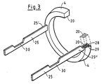
- the inner flange 4 is connected to a traction means 25 which is sealed between the casing 1 on the one hand and the packing 2 and the outer flange 3 on the other hand and is axially movably guided to the outside, so that it is on the outside in front of the outer flange 3 and the clamping nut 7 is accessible.
- the traction means 25 is a band that lies flat against the casing 1. It is guided in a loop, the two ends of the traction means 25 ', 25' are connected to the flange 4 and the loop apex 26 'lies in front of the outer flange 3 and the clamping nut 8.
- the traction ends 25 ', 25 ⁇ are connected to diametrically opposite points on the inner flange 4.
- the traction means 25 is held in a snap fit on the inner flange 4.
- This locking seat is formed by a locking head 28 at the traction end 25 ', 25, and a resiliently opening and then releasing the locking head locking receptacle 29 on the flange 4, the locking receptacle 29 then releasing the locking head 28 when the tractive force of the traction means 25 is a predetermined size exceeds.
- the traction means 25 can have a predetermined breaking point 30 close to the inner flange 4, which breaks when the traction force of the traction means 25 exceeds a predetermined size.
- the casing 1 is provided on the outside with a longitudinal groove 27, in which the traction means 25 passes under the clamping nut 7.
- the profile of the traction means is essentially matched to the profile cross section of the longitudinal groove 27 and fills the groove cross section.
- the wall bushing used in the wall opening is aligned so that the outer flange 3 abuts the outer wall surface.
- the inner flange 4 is moved axially against the packing 2 by pulling on the traction means 25, the packing rings 2 sliding axially one above the other and the packing 2 being compressed as a result. If the pack 2 is sufficiently pre-compressed in the breakthrough of the wall, a further increase in tractive force on the traction means 25 can result in the traction means ends 25 ', 25' detaching from the inner flange 4 and the traction means 25 being able to be pulled completely out of the wall duct.
- the final bracing of the wall duct is carried out with the help of the clamping nut 7, when tightening the casing 1 between the outer flange and the inner flange 4 serves as a tie rod, so that the two flanges 3, 4 are further approximated to one another and thus the packing finally in the wall breakthrough is tensioned.
Landscapes
- Engineering & Computer Science (AREA)
- Architecture (AREA)
- Civil Engineering (AREA)
- Structural Engineering (AREA)
- Gasket Seals (AREA)
- Pressure Vessels And Lids Thereof (AREA)
Applications Claiming Priority (2)
| Application Number | Priority Date | Filing Date | Title |
|---|---|---|---|
| DE3811442 | 1988-04-06 | ||
| DE19883811442 DE3811442C1 (fr) | 1988-04-06 | 1988-04-06 |
Publications (2)
| Publication Number | Publication Date |
|---|---|
| EP0336006A2 true EP0336006A2 (fr) | 1989-10-11 |
| EP0336006A3 EP0336006A3 (fr) | 1990-10-10 |
Family
ID=6351426
Family Applications (1)
| Application Number | Title | Priority Date | Filing Date |
|---|---|---|---|
| EP19880114175 Withdrawn EP0336006A3 (fr) | 1988-04-06 | 1988-08-31 | Traversée de mur |
Country Status (2)
| Country | Link |
|---|---|
| EP (1) | EP0336006A3 (fr) |
| DE (1) | DE3811442C1 (fr) |
Cited By (2)
| Publication number | Priority date | Publication date | Assignee | Title |
|---|---|---|---|---|
| DE3917447C1 (en) * | 1989-05-30 | 1990-04-19 | Plastoform Gmbh & Co Kg, 4973 Vlotho, De | Wall feedthrough for leads, cable, conduit etc. - has packing sealing circular space between feed=in tube and wall bore |
| DE4237478A1 (de) * | 1992-11-06 | 1994-01-27 | Eitle Rolf | Hauseinführung für Kabel |
Families Citing this family (1)
| Publication number | Priority date | Publication date | Assignee | Title |
|---|---|---|---|---|
| DE8911802U1 (de) * | 1989-10-04 | 1989-11-16 | Walter Rose Gmbh & Co Kg, 5800 Hagen | Vorrichtung zur Durchführung von Kabeln durch Gebäudewände |
Family Cites Families (3)
| Publication number | Priority date | Publication date | Assignee | Title |
|---|---|---|---|---|
| DE2901266C2 (de) * | 1979-01-13 | 1983-01-13 | Werner 7922 Herbrechtingen Hauff | Wanddurchführung für Kabel, Leitungen, Rohre od.dgl. |
| DE3623552C1 (en) * | 1986-07-12 | 1987-10-15 | Stewing Nachrichtentechnik | Device for sealing pipes, cables or similar tubular bodies which are to be led through wall openings |
| DE3731583C1 (de) * | 1987-09-19 | 1988-11-10 | Plastoform Gmbh & Co Kg | Mauerdurchfuehrung fuer Leitungen |
-
1988
- 1988-04-06 DE DE19883811442 patent/DE3811442C1/de not_active Expired
- 1988-08-31 EP EP19880114175 patent/EP0336006A3/fr not_active Withdrawn
Cited By (2)
| Publication number | Priority date | Publication date | Assignee | Title |
|---|---|---|---|---|
| DE3917447C1 (en) * | 1989-05-30 | 1990-04-19 | Plastoform Gmbh & Co Kg, 4973 Vlotho, De | Wall feedthrough for leads, cable, conduit etc. - has packing sealing circular space between feed=in tube and wall bore |
| DE4237478A1 (de) * | 1992-11-06 | 1994-01-27 | Eitle Rolf | Hauseinführung für Kabel |
Also Published As
| Publication number | Publication date |
|---|---|
| EP0336006A3 (fr) | 1990-10-10 |
| DE3811442C1 (fr) | 1989-06-08 |
Similar Documents
| Publication | Publication Date | Title |
|---|---|---|
| EP0379655B1 (fr) | Dispositif de raccordement | |
| EP1222421B1 (fr) | Raccord de tuyau avec fermeture rapide | |
| EP2025988B1 (fr) | Raccord pour un tuyau, en particulier un tuyau en plastique ou un tuyau composite en plastique et métal | |
| EP1097496A1 (fr) | Corps d'etancheite pour garnitures de cables | |
| DE69410267T2 (de) | Hydraulische reibungskupplung für wellen | |
| DE69430403T2 (de) | Selbstspannende Klemmschellenstruktur | |
| DE3631547A1 (de) | Kupplung fuer schlaeuche, rohre o. dgl., insbes. kunststoffschlaeuche | |
| EP0681135A2 (fr) | Dispositif pour le passage d'un conduit à travers une ouverture dans un mur | |
| DE3811442C1 (fr) | ||
| EP0100771B1 (fr) | Cuvelages pour le soutènement des tunnels et des puits | |
| DE19828838A1 (de) | Vorrichtung zur abgedichteten Verlegung von Rohren, Kabeln, Leitungen oder dergleichen Langformteilen durch Gerätewandungen | |
| DE202004011202U1 (de) | Moduldichtung für Leitungsdurchführungen | |
| DE2501889C3 (de) | RohrdichtscheUe | |
| DE3917447C1 (en) | Wall feedthrough for leads, cable, conduit etc. - has packing sealing circular space between feed=in tube and wall bore | |
| DE60107110T2 (de) | Sicherheitskupplung | |
| EP1006307A1 (fr) | Raccord enfichable | |
| EP0443118B1 (fr) | Anneau d'étanchéité divisé en matériau synthétique pour corps d'étanchéité de garnitures de câble | |
| EP0308697B1 (fr) | Traversée de mur pour conduits | |
| EP1523392A1 (fr) | Dispositif de serrage pour outils | |
| EP0392266B1 (fr) | Dispositif pour l'étanchement d'une ouverture de passage, par exemple pour garnitures de câbles et de tubes | |
| DE19505575C1 (de) | Vorrichtung zur Durchführung von Leitungen durch eine Öffnung in einer Wand | |
| EP0036535B1 (fr) | Accouplement à réparation | |
| DE4009706C1 (en) | Cable sealing for tubular conduit - provides packing with divided spreading sleeve as support element with cable support rings, sealing disc and wedge | |
| DE4039066C1 (en) | Connector for pressurised pipes with recessed housing | |
| DE29707044U1 (de) | Anschlußstück zur Verbindung eines Schlauches |
Legal Events
| Date | Code | Title | Description |
|---|---|---|---|
| PUAI | Public reference made under article 153(3) epc to a published international application that has entered the european phase |
Free format text: ORIGINAL CODE: 0009012 |
|
| AK | Designated contracting states |
Kind code of ref document: A2 Designated state(s): AT BE CH DE ES FR GB IT LI NL SE |
|
| PUAL | Search report despatched |
Free format text: ORIGINAL CODE: 0009013 |
|
| AK | Designated contracting states |
Kind code of ref document: A3 Designated state(s): AT BE CH DE ES FR GB IT LI NL SE |
|
| 17P | Request for examination filed |
Effective date: 19900904 |
|
| RAP1 | Party data changed (applicant data changed or rights of an application transferred) |
Owner name: HAUFF-TECHNIK GMBH & CO. KG |
|
| 17Q | First examination report despatched |
Effective date: 19920820 |
|
| STAA | Information on the status of an ep patent application or granted ep patent |
Free format text: STATUS: THE APPLICATION IS DEEMED TO BE WITHDRAWN |
|
| 18D | Application deemed to be withdrawn |
Effective date: 19921215 |