EP0336055A1 - Commande de la transmission de puissance à au moins deux essieux d'un véhicule à moteur - Google Patents
Commande de la transmission de puissance à au moins deux essieux d'un véhicule à moteur Download PDFInfo
- Publication number
- EP0336055A1 EP0336055A1 EP89101183A EP89101183A EP0336055A1 EP 0336055 A1 EP0336055 A1 EP 0336055A1 EP 89101183 A EP89101183 A EP 89101183A EP 89101183 A EP89101183 A EP 89101183A EP 0336055 A1 EP0336055 A1 EP 0336055A1
- Authority
- EP
- European Patent Office
- Prior art keywords
- speed
- arrangement according
- wheels
- value
- longitudinal
- Prior art date
- Legal status (The legal status is an assumption and is not a legal conclusion. Google has not performed a legal analysis and makes no representation as to the accuracy of the status listed.)
- Withdrawn
Links
Images





Classifications
-
- B—PERFORMING OPERATIONS; TRANSPORTING
- B60—VEHICLES IN GENERAL
- B60K—ARRANGEMENT OR MOUNTING OF PROPULSION UNITS OR OF TRANSMISSIONS IN VEHICLES; ARRANGEMENT OR MOUNTING OF PLURAL DIVERSE PRIME-MOVERS IN VEHICLES; AUXILIARY DRIVES FOR VEHICLES; INSTRUMENTATION OR DASHBOARDS FOR VEHICLES; ARRANGEMENTS IN CONNECTION WITH COOLING, AIR INTAKE, GAS EXHAUST OR FUEL SUPPLY OF PROPULSION UNITS IN VEHICLES
- B60K23/00—Arrangement or mounting of control devices for vehicle transmissions, or parts thereof, not otherwise provided for
- B60K23/08—Arrangement or mounting of control devices for vehicle transmissions, or parts thereof, not otherwise provided for for changing number of driven wheels, for switching from driving one axle to driving two or more axles
- B60K23/0808—Arrangement or mounting of control devices for vehicle transmissions, or parts thereof, not otherwise provided for for changing number of driven wheels, for switching from driving one axle to driving two or more axles for varying torque distribution between driven axles, e.g. by transfer clutch
Definitions
- the invention relates to an arrangement according to the preamble of the main claim.
- Motor vehicles with permanent all-wheel drive require a compensation device, for example in the form of a center differential, to avoid tension in the drive train between the two axles. This enables speed differences between the wheels of both axles, such as occur when cornering or tires with different rolling radii.
- DE-0S 35 05 455 discloses a device for automatically switching on and off drive elements of a motor vehicle.
- the motor vehicle is normally driven via only one axle.
- driving dynamics limit values such as a certain speed slip between the wheels of two axles, a second drive axle, a differential lock, a rear axle and a front axle differential lock are engaged in stages via a switchable clutch and a differential.
- adaptation electronics are also provided, which corrects the measured wheel speed values accordingly.
- the difficulty arises that, although the drive components are switched on correctly, the locks can no longer be switched off under certain operating conditions solely dependent on slip; because when the lock is fully engaged, this prevents differences in the speed of the wheels, and it is irrelevant whether the differences in speed are caused by different rolling radii of the wheels or by a loss of grip.
- the (nevertheless) corrected wheel speed values make the switch-off decision even more difficult.
- the invention provides an arrangement for controlling the power transmission on at least two axles of a motor vehicle, which has a friction member for limiting speed compensation between the axles with a minimal amount of sensor-sensed operating and / or controls driving parameters in such a way that an overall behavior of the motor vehicle which is optimal in terms of driving dynamics is achieved in almost all driving situations.
- the measurement and control engineering effort for this is low, since the control can be largely integrated into a control unit of an anti-lock braking system (ABS).
- ABS anti-lock braking system
- the control via speed-dependent tolerance bands for speed differences between the driven axles results in a calming of the actuating behavior on the one hand and on the other hand a smooth but sufficiently fast transition behavior between the states of the unlimited compensation effect and the completely restricted speed compensation.
- a limit criterion for influencing the limitation of the compensating effect of the center differential is adapted for wheels with different rolling radii. This ensures that no additional measured values or criteria have to be used to switch off or reduce the limitation of the compensating effect.
- a curve adaptation also ensures that even tight curve radii can be negotiated without problems, particularly in the lower speed range, and that an inadmissibly high slip occurring on an axle is correctly recognized.
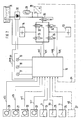
- Fig. 1 denotes an all-wheel drive motor vehicle with a first driven axle 2 (rear axle) and a second driven axle 3 (front axle); e.g. B. in the area of the first axis 2, here and in a not necessary manner in the rear area of the motor vehicle 1, an internal combustion engine 4 is arranged, which has a controllable, preferably electro-hydraulically actuated differential brake via a clutch-transmission unit 5 and a center differential 6 Limiting the compensating effect drives a transverse differential 7 of the first axle 2, which is preferably continuously limited or controllable in its compensating action, and a differential 8 of the second axle 3.
- This is usually designed as a conventional differential gear; but it can also be a self-locking or continuously limiting or compensating.
- Wheels 9, 10 on the second axle 3 are designed to be steerable, while wheels 11, 12 on the first axle are not steerable.
- Actuators 13, 14 for controlling the limitation of the compensating effect of the transverse differential 7 and the center differential 6 are only shown symbolically, as is a dashed line actuator 15 on the differential 8 of the second axle 3, which is only required in the case of a continuously controllable differential; the actuators can be flanged to the aggregates, integrated wholly or partially in them or at least partially arranged outside of them and connected to them mechanically, hydraulically, pneumatically or electrically.
- the arrangement can of course also be used in all-wheel drive systems with a controllable longitudinal clutch, as are known for example from DE-PS 36 08 059.
- the control device 16 shown in FIG. 2 with its input and output variables represents a configuration in which, in addition to the actuator 14 of the center differential 6, the actuator 13 of the transverse differential 7 is also controlled. A certain number of the connected sensors is sufficient; if necessary, they can be supplemented by dashed sensors. Activation of the actuator 15 is not shown and corresponds to that of the actuator 13.
- the control unit 16 is preferably constructed on the basis of a microcomputer system known per se (for example Intel 8096) and can be structurally combined with a control unit of an anti-lock braking system (ABS) or a traction control system (ASR) or integrated in at least one of these systems or connected via a bus system be.
- ABS anti-lock braking system
- ASR traction control system
- the structure of the control unit corresponds to a conventional microcomputer configuration with a central unit, volatile and non-volatile memories (RAM, ROM, EPROM, EEPROM), input and output modules, timers, etc .; therefore the structure is not discussed in detail.
- indicator lights 17, 18 and 19 are arranged in the dashboard area of the motor vehicle and show a driver information about an instantaneous state of the arrangement, e.g. B. which differential brake is activated (center differential: indicator light 17; transverse differential: indicator light 18); possible errors in the arrangement can also be displayed (indicator light 19).
- the word "sensoric” is not necessarily to be seen only in the eventual sole acquisition of a measured variable or in a conversion of the measured variable into another physical variable, it can also mean the processing or preprocessing of one or more recorded variables.
- the control unit 16 receives signals vfl, vfr, vrl and vrr from the sensors 20 and 21 assigned to the wheels 10 and 9 and the sensors 22 and 23 assigned to the wheels 12 and 11, which signals the speeds of these wheels correspond to the second and first axles 3, 2 or the control unit 16 converts corresponding signals or values in the wheel speed.
- the control unit 16 also receives signals b, hb, tr from a brake light switch 24, from a handbrake switch 25 and from a traction switch 26, with which a complete locking of the center differential 6 and / or the transverse differential 7 can be controlled.
- the pump unit contains its own pressure control circuit, which controls it so that the accumulator is charged to a certain pressure level range. If the pressure falls below the safety pressure, the entire device is depressurized and the indicator light 19 is activated.
- the control unit 16 controls a first pressure build-up valve 32 via a line spl, which connects the actuator 14 for the differential brake of the center differential 6 to the pressure accumulator 29.
- a first pressure relief valve 33 is activated via a line sul; this connects the actuator 14 to the sump 31st
- control unit 16 supplies control signals for a second pressure build-up valve 34 via an output line spq, which connects the actuator 13 of the transverse differential 7 to the pressure accumulator 29.
- a second pressure relief valve 35 is actuated via a line suq can connect to the swamp.
- a safety valve 36 is connected in the pressure medium line between the accumulator 29 and the pressure build-up valves 32, 34.
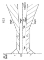
- FIG. 3 shows a diagram on which control criteria are shown, according to which the control device 16 controls a pressure level in the actuator 14 of the center differential 6.
- the vehicle speed v is plotted in km / h on the abscissa; this corresponds to the true tangential vehicle speed above ground and is preferably taken from the slowest running wheel, but can also be derived from the wheel speed signals or speeds vfl, vfr, vrl, vrr according to other known criteria.
- which increases approximately linearly with the driving speed v stat Sgeo * v occurs, which may cross the tolerance bands and thus lead to an undesirable or unnecessary tax influence. If the rolling radii of the wheels are selected axially and the output ratios of the center differential are deliberately chosen differently, the tolerance bands are to be shifted so that they in turn are approximately symmetrical about the stationary longitudinal speed difference dvl
- the first tolerance band now consists of an upper limit dvgph and a lower limit dvgpl, which are each speed-dependent: If the longitudinal speed difference dvl exceeds the upper limit dvgph, the limitation of the speed compensation is increased by activating the first pressure build-up valve 32; - If the longitudinal velocity difference dvl is within the first tolerance band I, ie between the upper limit dvgph and its lower limit dvgpl, the instantaneous pressure is maintained, ie neither the first pressure build-up valve 32 nor the first pressure release valve 33 receives new control signals; - If the longitudinal speed difference dvl lies between the two tolerance bands, the pressure relief valve 33 is activated (reducing the limitation of the compensating effect); - If the longitudinal speed difference dvl is within the second tolerance band II, ie between its upper limit dvgnl and its lower limit dvgnh, no new control signals are again output to the valves 32, 33; - If, on the
- the tolerance bands I, II and their upper limits dvgph, dvgnl and lower limits dvgpl, dvgnh are dependent on the vehicle speed.
- the first tolerance band I (or its upper and lower limit dvgph, dvgpl) located in the range of positive longitudinal speed differences dvl> 0 is preferred with increasing driving speed v - falling (or constant) in a lower speed range 0 ⁇ v ⁇ vga, - constant and in a medium speed range vga ⁇ v ⁇ vgb - increasing in an upper speed range v> vgb.
- the second tolerance band II (or its upper and lower limits dvgl, dvgnh) located in the range of negative longitudinal speed differences dvl ⁇ 0 is preferred with increasing driving speed v - increasing or constant in a lower speed range 0 ⁇ vga, - constant and in a medium speed range vga ⁇ v ⁇ vgb - falling in an upper speed range v> vgb.
- the values given in FIG. 3 are only to be regarded as guidelines. However, for good effectiveness of the arrangement, it has proven to be useful to set the tolerance bands in such a low range that the driving behavior of a four-wheel drive vehicle could be decisively improved.
- Sgeo (vr-vf) / vf
- the slope of the tolerance band limit corresponds at least approximately to the increase in the longitudinal speed difference dvl corresponding to the above. selected value of the axle slip S.
- the gradient can also take into account that the speeds calculated from the signals of the speed sensors 20 to 23 are subject to increasing fluctuations at higher driving speeds.
- the lower limit dvgnh of the lower tolerance band II and / or the upper limit dvgph of the upper tolerance band I is preferably designed so that it is an envelope for those that occur when the motor vehicle is cornering speed-dependent longitudinal speed differences dvl corresponds.
- the lower limit dvgnh / the upper limit dvgph can, however, also be designed higher / lower; then, however, a curve correction device must be provided (see below), which takes into account the longitudinal speed-dependent differences in speed when cornering.
- the pressure build-up and relief valves 32 to 35 are controlled by the control unit via pulse-shaped signals (pulse series).
- the pulse-shaped signals are designed in such a way that the rate of change with which the limitation of the speed compensation occurs can be controlled (and finally).
- This rate of change is advantageous for increasing and decreasing the limitation. It can also depend on the magnitude of the amount of the longitudinal velocity difference
- auxiliary energy sources e.g. storage pressure
- a pulse series for actuating the first pressure build-up valve 32 has, for example, the following chronological sequence (a plus sign (+) after the time indicates an activation pulse (open valve), a minus sign (-) an impulse pause (no actuation)): 4ms + 20ms- 4ms + 20ms- 8ms + 20ms- 8ms + 20ms- 8ms + 20ms- l2ms + 20ms- l2ms + 20ms- l2ms + 20ms- 36ms +.
- a pulse series for actuating the first pressure reduction valve 33 has the following course: 4ms + 240ms- 4ms + 240ms- 4ms + 180ms- 4ms + 180ms- 8ms + 180ms- 8ms + 180ms- l2ms + 180ms- l2ms + 180ms- l2ms + 60ms- 36ms +.
- a requested pressure build-up pulse series is sent a switch-on pulse with an extended pulse duration, which can also be dependent on the storage pressure (for which the storage pressure detection (sensor 28) is of course necessary).
- the pulse of extended pulse duration serves to fill the still empty (unpressurized) lines to the actuator 14 and this itself (reducing the dead time of the arrangement).
- a request to hold or reduce the limitation that follows a request to increase or limit the speed compensation in a finite time can be delayed and / or suppressed.
- a series of build-up pulses from the computer is interrupted and a current pulse is output when the longitudinal velocity difference dvl occurs in one of the tolerance bands. It continues when dvl again exceeds the first tolerance band I or falls below the second tolerance band II.
- a pressure reduction pulse series is only released after a certain period of time has elapsed.
- the shortest pulse duration (4msec) corresponds to a control time that the valves just need to open safely. It is advantageous if the program cycle time of a control program described below corresponds to the duration of this control time or the control time of the valves is an integral multiple of the program cycle time.
- control unit receives additional signals b, hb from the brake light switch 24 and / or the ABS and / or the handbrake switch 25, the actuator 14 is activated in such a way that when the service brake is actuated it is slower and when the ABS becomes effective or when the handbrake is actuated faster Pressure reduction takes place.
- the ratio of the duration of switch-on pulses to pulse pauses can be reduced with increasing pressure or increased with falling pressure.
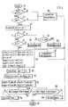
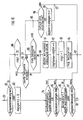
- FIG. 4 shows a flowchart for the sequence of a program module for the control unit 16, which is preferably integrated within a program of an ABS control unit or a main program (not shown). These include a. a system initialization, as well as the cyclical processing of a checking routine for all elements connected to the control unit 16, a recording and processing routine for the sensor signals with the determination of the wheel speeds and accelerations and the program module according to FIG. 4.
- a subroutine 39 which delivers control pulses sul to the pressure reduction valve 33 for a rapid pressure reduction in the actuator 14, and continues to the end of the program 40; there is either a return to the ABS program or to the main program.
- a further query 47 checks whether the service brake of the motor vehicle is actuated (signal b active): if so, a subroutine 48 for slow pressure reduction in actuator 14 is called and, after its expiration, the program branches to program end 40 .
- limit criteria such as. B. speed or slip thresholds of the tolerance bands can be used as a cut-in and cut-out criterion or cut-in and cut-out criteria for friction elements to limit speed compensation.
- the limit criteria for good, load-change-free effectiveness must be very low (switch-on threshold, for example with a ratio of longitudinal speed difference to driving speed or with an axle slip value of approx. 1%).
- This situation is made clear by a dash-dotted line 57 in FIG. 5.
- This line 57 corresponds to a stationary longitudinal speed difference dvl
- stat Sgeo * v, which arises when a rolling circumference of the wheels of a first axle is only 1% smaller than a rolling circumference of the wheels of a second axle; line 57 therefore increases linearly with vehicle speed v.
- DE-0S 35 05 455 it has therefore already been proposed to provide an electronic unit for controlling clutches or locks of differential gears with adaptive electronics which compensate measured values of the wheel speeds (or speeds) in accordance with the deviations which normally occur.
- the longitudinal speed difference values dvl now run along the line 58, so that above a certain driving speed v (80 km / h) the connection limit criterion relevant for the negative range of longitudinal speed differences is no longer exceeded.
- the lock thus remains switched on, although there is no longer an impermissibly high wheel slip on an axle. Without additional (critical and wheel slip-dependent) switch-off criteria, however, this leads to strong tension in the drive train and increased wear on the friction elements and on the vehicle tires.
- the dash-dotted line ds now indicates exactly the correction value that is linearly dependent on the driving speed, by which the limit criterion (in the given case the tolerance band I according to FIG. 3) is shifted (adapted) (additive), so that the adapted tolerance band I 'results .
- the mode of operation is such that when the friction member is switched off or deactivated and the wheels are running smoothly or with the same wheel slip, the values for the longitudinal speed differences settle around the line ds. If, for example, an additional (positive) speed longitudinal difference amount occurs so that the upper limit dvgph 'of the first tolerance band I' is exceeded, the friction element is switched on or on.
- the friction limiter limiting the speed compensation now pulls the longitudinal speed difference dvl downwards in the direction of the v-axis with increasing control and is no longer activated when dvl enters the adapted first tolerance band I 'and is switched off or off again when the lower limit dvgpl' is undershot.
- the correction value is recorded when the wheels are running without slip or with the same wheel slip.
- This state is simulated by the following system states: - the limitation of the speed compensation is lifted, - the vehicle speed (v) is within a certain speed window, - the amount of wheel accelerations (dvfl / dt, dvfr / dt, dvrl / dt and dvrr / dt) of all wheels is below a certain maximum wheel acceleration value, - The motor vehicle is not cornering - no vehicle brakes are applied and / or - The amount of a static and / or dynamic longitudinal acceleration (dv / dt) of the motor vehicle is below a certain maximum longitudinal acceleration value.
- / vf, dvqr
- / vr is in each case smaller than a transverse speed difference value dvqg and / or - An amount of a relative longitudinal speed difference dvlr
- / v and dvll
- the longitudinal acceleration of the motor vehicle can be determined using an acceleration sensor or an acceleration switch.
- the correction value ds is determined and its adaptation to the changes in the driving mode of the motor vehicle is carried out in a sensible manner at a finite adjustment speed;
- the adjustment factor abfak is advantageously determined by means of moving averages. Since major changes to the rolling radii of the wheels often occur after the vehicle has come to a standstill (wheel change, pressure loss, fitting snow chains), it is necessary to determine the correction value immediately after starting the motor vehicle or its internal combustion engine at a higher adjustment speed than during driving operation; For this purpose, it is first set to a value which was saved immediately after the last valid value was switched off.
- the adjustment factor abfak is thus determined with a short time constant, whereby for each program run of a calculating program for a moving average, abfakmw the adjustment factor abfak, this is composed of 1 / n of a newly determined value to (n-1) / n of a previously determined value.
- the newly determined value is compared with the stored value and only calculated with the new value if the amount is greater than the old value and / or has changed its sign; otherwise the old value is used.
- / vr) / 2 or from the amount of the difference in the average speeds the wheels on each side of the vehicle dvq
- the curve correction value dvk (dash-dotted line) is shown in a diagram in FIG. 8, on the abscissa of which the relative transverse speed difference dvg (in%) or a curve radius r, and on the ordinate of which the longitudinal speed difference dvl is plotted in km / h.
- the correction value dvk represents an approximation to the value pairs of the longitudinal velocity difference dvl and the relative transverse velocity difference dvg that occur for different values of the vehicle lateral acceleration aq.
- the dashed line dvkmin represents the maximum amount for the value pairs dvl, dvq. If the value pairs dvl, dvqr lie above the dash-dotted line dvkmax, there is no curve correction because the motor vehicle is already outside the stability range there.
- FIG. 9 shows a basic sequence for determining the correction value of the limit criteria adaptation: after program start 49, a query is made as to whether a comparison counter is abz, which is set to zero when the motor vehicle is started and is increased under certain circumstances per program run, whether it is the same Is zero, 60. If so, a variable adjustment factor (abfak) is loaded from a non-volatile memory, 61, and the adjustment counter is set to 1, 62 and continues to a branch point 63, which is also reached if condition 60 is not met.
- abz a comparison counter
- abz a variable adjustment factor
- Adjustment conditions 64 are then determined and queried 65 whether these are met. If this is not the case, it is checked under a condition 66 whether the friction member control has been active for too long (i.e. that the friction member is not depressurized); if no, the process continues to a branch point 67, if yes, an emergency program 68 is started which sets the adjustment factor to maximum deviation under certain conditions and proceeds to branch point 67 and from there to a further branch point 69.
- query 72 If the query 72 is positive (driving operation), then a slow comparison takes place over a larger number of program runs 73, from which a comparison factor abfak and a comparison factor mean value abfakmw results. Then jump to point 69. If, on the other hand, query 72 is negative, there is a state of an incomplete quick adjustment and a quick adjustment 74 takes place, from which an adjustment factor mean value abfakmw results.
- the adjustment counter abz is incremented, 75 and queried whether it has reached the specific value (20), 76; if no, there is a jump to point 69, if so, it is determined under the conditions already described above, 77 whether the comparison factor abfak that was used before the quick comparison or the calculation mean value accumulated meanwhile is continued, and also to the point 69 jumped.
- the correction value ds is set to zero, 78, the subroutine curve correction 79 is called and the amount of the longitudinal speed difference
- Fig. 10 it is first queried whether the friction element control is active, 82. If no, an adjustment locking time cut off is set to zero, 83. Then it is queried whether the driving speed v lies within a specific speed window, 84; if no, a branch is made to point 67, if yes, a query is made 85 as to whether the wheel accelerations of all wheels are less than a maximum value. If no, there is a jump to point 67, if yes, a check is made 86 as to whether the vehicle is cornering. For this purpose, it is checked whether the amounts of the relative transverse speed difference
- an 'emergency program' is started; a query is made as to whether the adjustment counter abz is less than a value of 20. If so, the program is in start mode (immediately after the motor vehicle has started) or after one Emergency function, and after passing through a first period of time (query 89) and a branching point 90, the adjustment factor abfak is set to maximum deviation (caused, for example, by snow chains or an emergency wheel on one axis), 91 and the adjustment factor mean abfakmw becomes a multiple, for example set four times the adjustment factor, 92, the adjustment counter set to 1, 93 and a "emergency function" flag set, 94 and returned to point 67.
- a query is made as to whether a time loop 96 has expired; if no, after a branch point 97 has been passed through, a return is made to point 67; if yes, the adjustment lock time is incremented, 98 is jumped to, and jumped to point 97.
- query 88 If query 88 is not fulfilled, the program is in driving mode and a query 99 is made as to whether a second longer period of time has been reached; if this is the case, the process jumps to point 90 (increasing the adjustment factor abfak), if not, to point 95.
- the adjustment counter abz, 72 is first queried after passing through point 70 and program step 71. If this is greater than or equal to the value 20 that limits the start operation, a slow adjustment takes place by a new one Adjustment factor mean abfakmw is set to the value of the old adjustment factor mean abfakmw, minus the adjustment factor abfak, plus the first temporary variable tmpo, 100, and the adjustment factor abfak is set to a certain divided by a higher quotient (256) Adjustment factor mean set abfakmw, 101 and after passing a point 102 is returned to point 69.
- a second temporary variable tmp2 is set to a value which is obtained by dividing the average comparison factor abfakmw by a smaller quotient (4), 103.
- a new value of the abfakmw is changed to the old one
- the value of the abfakmw is set, from which the second temporary quantity tmp2 is subtracted and to which the first temporary quantity tmp0 is added, 104.
- the adjustment counter abz is incremented, 105, and queried, 106 whether the adjustment counter deduces the value which indicates the end of the fast adjustment (20) has reached; if no, there is a return via point 102 to point 69; if yes, the second temporary variable tmp2 is set to a value which results from the adjustment factor mean value abfakmw divided by the smaller quotient (4), 107.
- a query is made as to whether the flag emergency function is set, 108. If so, after passing a point 109, the adjustment factor abfak is set to the second temporary variable tmp2, 110, a new adjustment factor mean abfakmw from the old value of the old adjustment factor mean abfakmw, multiplied by determined value (64), 111, and the emergency function flag reset, 112 and returned to point 69.
- the query is whether the second temporary variable tmp2 is greater than zero, 113. If so, a further query is made as to whether the second temporary variable tmp2 is greater than the adjustment factor. 114, if yes, a jump is made via point 115 to point 109, if no, after passing a point 116, the adjustment factor mean abfakmw is abfakm to the value of the adjustment factor multiplied by the value of the higher quotient (256), 117 and returned to point 69.
- query 113 If query 113 is negative, it is queried whether the second temporary variable tmp2 is smaller than the adjustment factor, 118; if yes, the program branches to point 115, if not to point 116.
- the program branch between points 109 and 69 characterizes that system state in which, after the start phase has ended, the newly calculated one
- the value of the adjustment variable is continued, while the program branch between points 116 and 69 includes the case where the value from the quick adjustment is continued.
- the correction value ds is now determined by first setting it to zero 78 and calling the program 79 to determine a curve correction value dvk; this is added there to the correction value ds. Subsequently, a query is made as to whether the longitudinal speed difference dvl is greater than or equal to zero, 119. If no, dvl is inverted, 120 and a query is made as to whether the adjustment factor abfak is less than zero, 121; if not, the program is ended after passing through a point 122, since then the adjustment factor is abfak and the longitudinal speed difference dvl are in different quadrants of the longitudinal speed difference-speed diagram and are therefore not corrected or only corrected due to cornering.
- a jump is made to a point 123, from which the first temporary variable tmp0 is set to a value which is derived from the adjustment factor (corresponding to the slope of the correction line), multiplied by the current vehicle speed v (or the average speed of the wheels on the second axle as a reference for the true ground speed), results 124.
- a query is made as to whether it is greater than or equal to zero; if yes, the process proceeds to a point 126; if no, the first temporary quantity tmpo is inverted, 127 and after passing the point 126 a new value of the correction value ds is determined by adding the first temporary quantity to the old correction value (ie the curve correction) tmp0 is added, 128; then the program is ended, 81.
- query 119 If query 119 is positive, it is queried 129 whether the adjustment factor abfak is less than zero. If so, proceed to point 122, if not, point 123.
- condition 131 is not met or at least one of conditions 132 to 134 is met, the curve is not corrected and the program is ended, 135.
- the two queries 133, 134 and the value k 2 ensure that the curve correction takes place only within a reasonable range of curve radii, for example 4.5 m ⁇ r ⁇ 14.7 m.
- the values 4 and 256 for the formation of the adjustment factors and mean values as well as the value 20 for the adjustment counter are values that depend on the program cycle time and the valve dynamics and do not necessarily have to be in this order of magnitude. However, they have proven to be useful with the given arrangement.
- the value 20 for the value that characterizes start-up operation results from the fact that with a moving averaging for the adjustment factor with the quotient 4 (1/4 of the newly calculated value is added to the sum of 3/4 of the old), this after 20 calculations has practically reached its end value (step response); this corresponds to an adjustment time of approx. 80ms. With slow adjustment, 1/256 of the new adjustment value is always added to 255/256 of the old adjustment value; the answer to a jump reaches about 90% of its final value after about 3 seconds.
Landscapes
- Engineering & Computer Science (AREA)
- Chemical & Material Sciences (AREA)
- Combustion & Propulsion (AREA)
- Transportation (AREA)
- Mechanical Engineering (AREA)
- Regulating Braking Force (AREA)
- Arrangement And Driving Of Transmission Devices (AREA)
Applications Claiming Priority (2)
| Application Number | Priority Date | Filing Date | Title |
|---|---|---|---|
| DE3811214 | 1988-04-02 | ||
| DE3811214A DE3811214C2 (de) | 1988-04-02 | 1988-04-02 | Anordnung zur Steuerung der Kraftübertragung auf wenigstens zwei Achsen eines Kraftfahrzeuges |
Publications (1)
| Publication Number | Publication Date |
|---|---|
| EP0336055A1 true EP0336055A1 (fr) | 1989-10-11 |
Family
ID=6351279
Family Applications (1)
| Application Number | Title | Priority Date | Filing Date |
|---|---|---|---|
| EP89101183A Withdrawn EP0336055A1 (fr) | 1988-04-02 | 1989-01-24 | Commande de la transmission de puissance à au moins deux essieux d'un véhicule à moteur |
Country Status (4)
| Country | Link |
|---|---|
| US (1) | US4961476A (fr) |
| EP (1) | EP0336055A1 (fr) |
| JP (1) | JPH01309825A (fr) |
| DE (1) | DE3811214C2 (fr) |
Cited By (7)
| Publication number | Priority date | Publication date | Assignee | Title |
|---|---|---|---|---|
| EP0393596A3 (fr) * | 1989-04-19 | 1991-03-13 | Nissan Motor Co., Ltd. | Système de répartition du couple pour véhicule à quatre roues motrices |
| EP0438178A1 (fr) * | 1990-01-19 | 1991-07-24 | Mazda Motor Corporation | Système de réglage de différentiel pour véhicules à quatre roues motrices |
| EP0659605A3 (fr) * | 1993-12-23 | 1995-10-18 | Borg Warner Automotive | Système d'entrainement de véhicule sur demande. |
| EP1795391A1 (fr) * | 2005-12-09 | 2007-06-13 | Borgwarner, Inc. | Dispositif hydraulique de commutation et procédé de commande des embrayages d'un système de gestion du couple d'un véhicule à essieux multiples |
| WO2011124856A1 (fr) * | 2010-04-08 | 2011-10-13 | Renault S.A.S. | Procédé de commande du fonctionnement d'un moyen de couplage mécanique des premier et deuxième essieux d'un véhicule automobile |
| FR2958584A1 (fr) * | 2010-04-12 | 2011-10-14 | Renault Sas | Procede d'alerte de glissement d'un coupleur. |
| CN103517821A (zh) * | 2011-02-18 | 2014-01-15 | 捷豹路虎有限公司 | 车辆以及控制车辆的方法和系统 |
Families Citing this family (28)
| Publication number | Priority date | Publication date | Assignee | Title |
|---|---|---|---|---|
| DE59006263D1 (de) * | 1989-12-16 | 1994-07-28 | Bosch Gmbh Robert | Antiblockierregelsystem. |
| JPH03217336A (ja) * | 1990-01-19 | 1991-09-25 | Mazda Motor Corp | 車両の差動制限装置 |
| DE4327491C2 (de) * | 1993-08-16 | 1996-08-29 | Daimler Benz Ag | Verfahren zum Abgleichen der Raddrehzahlen für ein Kraftfahrzeug |
| DE4430462A1 (de) * | 1994-08-27 | 1996-02-29 | Teves Gmbh Alfred | Verfahren zum schnellen Erkennen eines Notrades |
| US5809443A (en) * | 1994-12-09 | 1998-09-15 | Ford Motor Company | Four-wheel drive transfer case controller with compensation for tires with different diameters |
| US5927426A (en) * | 1996-10-18 | 1999-07-27 | Itt Automotive Inc. | Traction control system for use with four wheel drive vehicles having on-demand transfer cases |
| US5954778A (en) * | 1996-11-26 | 1999-09-21 | Ford Global Technologies, Inc. | Four-wheel drive transfer case controller with torque decrement strategy |
| US6047231A (en) * | 1997-06-06 | 2000-04-04 | Ford Global Technologies, Inc. | Four wheel drive transfer case controller compatible with a spare tire |
| US5979584A (en) * | 1997-07-25 | 1999-11-09 | Ford Global Technologies, Inc. | Four-wheel drive transfer case controller |
| WO1999023539A1 (fr) * | 1997-10-31 | 1999-05-14 | Hitachi, Ltd. | Appareil de commande de vehicule |
| US6353399B1 (en) | 2000-10-11 | 2002-03-05 | Ford Global Technologies, Inc. | Robust encoding scheme for a shift motor encoder assembly and a system using the same |
| DE10148282B4 (de) * | 2000-11-27 | 2015-04-02 | Continental Teves Ag & Co. Ohg | Antriebsschlupfregelungsverfahren mit Antriebsmotorregelungseingriff für Kraftfahrzeuge |
| DE10244070A1 (de) * | 2002-09-06 | 2004-03-11 | Volkswagen Ag | Vorrichtung und Verfahren zur Lenkunterstützung für Fahrzeuge mit elektromechanischer Lenkung |
| DE10248214A1 (de) | 2002-10-16 | 2004-05-13 | Siemens Ag | Schaltung mit mindestens einem Piezoaktor |
| US6752233B1 (en) | 2003-02-11 | 2004-06-22 | General Motors Corporation | Selectable overspeed secondary drive module |
| US6964460B2 (en) * | 2003-12-03 | 2005-11-15 | Delphi Technologies, Inc. | Brake controller and method for controlling a brake system |
| US20070088605A1 (en) * | 2005-10-19 | 2007-04-19 | Yahoo! Inc. | System and method for achieving linear advertisement impression delivery under uneven, volatile traffic conditions |
| DE102006022858A1 (de) * | 2006-05-16 | 2007-11-22 | Magna Powertrain Ag & Co Kg | Druckabbaueinheit für eine hydromechanische, auf eine Drehzahldifferenz ansprechende Kupplung |
| US8041492B2 (en) * | 2006-10-31 | 2011-10-18 | Clark Equipment Company | Engine load management for power machines |
| US20080255936A1 (en) * | 2007-04-13 | 2008-10-16 | Yahoo! Inc. | System and method for balancing goal guarantees and optimization of revenue in advertisement delivery under uneven, volatile traffic conditions |
| DE102007021303B4 (de) | 2007-05-07 | 2015-12-24 | Magna powertrain gmbh & co kg | Verfahren und Vorrichtung zum Erzeugen eines Stellsignals für einen Aktuator einer Kupplungseinheit eines Kraftfahrzeugs |
| WO2010028629A1 (fr) * | 2008-09-10 | 2010-03-18 | Continental Teves Ag & Co. Ohg | Procédé d'assistance à la direction en cas de manœuvre d'urgence |
| DE102009026813A1 (de) * | 2009-06-08 | 2010-12-09 | Robert Bosch Gmbh | Verfahren zur Erzeugung eines auf die Fahrzeugräder eines Fahrzeugs wirkenden Differenzmoments |
| JP5533344B2 (ja) * | 2010-06-29 | 2014-06-25 | 日産自動車株式会社 | 駆動力配分装置 |
| DE102011012593A1 (de) | 2011-02-28 | 2012-08-30 | Engineering Center Steyr Gmbh & Co. Kg | Steuerverfahren für eine Kupplung im Antriebsstrang eines Kraftfahrzeugs |
| DE102015004694B3 (de) * | 2015-04-11 | 2016-07-28 | Audi Ag | Erfassen einer Betätigung eines Bedienelements in einem Kraftfahrzeug |
| CN111094797B (zh) | 2017-09-19 | 2023-10-27 | 庞巴迪动力产品公司 | 针对湿滑驾驶条件而优化的限滑差速器的控制 |
| WO2019058227A1 (fr) * | 2017-09-19 | 2019-03-28 | Bombardier Recreational Products Inc. | Commande d'un différentiel autobloquant reposant sur un angle de direction d'un véhicule |
Citations (5)
| Publication number | Priority date | Publication date | Assignee | Title |
|---|---|---|---|---|
| DE3626025A1 (de) * | 1985-08-05 | 1987-03-19 | Nissan Motor | Antriebseinrichtung zur steuerung und verteilung der antriebskraft fuer ein kraftfahrzeug mit allradantrieb |
| EP0215352A1 (fr) * | 1985-08-30 | 1987-03-25 | Mazda Motor Corporation | Système de commande du couple pour véhicules |
| EP0216318A1 (fr) * | 1985-09-21 | 1987-04-01 | Adam Opel Aktiengesellschaft | Agencement de transmission |
| DE3631180A1 (de) * | 1985-09-13 | 1987-04-02 | Nissan Motor | Steuersystem fuer die verteilung des antriebsdrehmoments bei einem 4-rad-antrieb fuer ein fahrzeug |
| EP0245069A1 (fr) * | 1986-05-06 | 1987-11-11 | Toyota Jidosha Kabushiki Kaisha | Méthode et dispositif de régulation pour contrôler le différentiel central bloquable d'un véhicule à quatre roues motrices par rapport à la différence du nombre de tours des roues avant et des roues arrière |
Family Cites Families (8)
| Publication number | Priority date | Publication date | Assignee | Title |
|---|---|---|---|---|
| US4032197A (en) * | 1976-05-04 | 1977-06-28 | Abex Corporation | Slip/slide detector control circuit |
| DE3205627A1 (de) * | 1981-04-30 | 1982-11-18 | Robert Bosch Gmbh, 7000 Stuttgart | Antriebsschlupfregelung |
| JPS59109431A (ja) * | 1982-12-16 | 1984-06-25 | Fuji Heavy Ind Ltd | 4輪駆動車の切換制御装置 |
| DE3608059C1 (en) * | 1984-10-12 | 1987-07-09 | Porsche Ag | Arrangement for controlling the power transmission of a four-wheel drive vehicle |
| DE3505455A1 (de) * | 1985-02-16 | 1986-08-28 | Daimler-Benz Ag, 7000 Stuttgart | Vorrichtung zum automatischen zu- und abschalten von antriebselementen eines kraftfahrzeuges |
| US4896738A (en) * | 1986-06-20 | 1990-01-30 | Fuji Jukogyo Kabushiki Kaisha | Power transmitting system for a four-wheel drive vehicle |
| JPH0818502B2 (ja) * | 1986-06-30 | 1996-02-28 | アイシン・エィ・ダブリュ株式会社 | 前後輪係合機構を備えた4輪駆動車 |
| DE3718421A1 (de) * | 1987-06-02 | 1988-12-15 | Teves Gmbh Alfred | Schaltungsanordnung fuer bremsanlagen mit blockierschutz- und/oder antriebsschlupf-regelung |
-
1988
- 1988-04-02 DE DE3811214A patent/DE3811214C2/de not_active Expired - Fee Related
-
1989
- 1989-01-24 EP EP89101183A patent/EP0336055A1/fr not_active Withdrawn
- 1989-03-30 US US07/330,762 patent/US4961476A/en not_active Expired - Fee Related
- 1989-03-31 JP JP1078713A patent/JPH01309825A/ja active Pending
Patent Citations (5)
| Publication number | Priority date | Publication date | Assignee | Title |
|---|---|---|---|---|
| DE3626025A1 (de) * | 1985-08-05 | 1987-03-19 | Nissan Motor | Antriebseinrichtung zur steuerung und verteilung der antriebskraft fuer ein kraftfahrzeug mit allradantrieb |
| EP0215352A1 (fr) * | 1985-08-30 | 1987-03-25 | Mazda Motor Corporation | Système de commande du couple pour véhicules |
| DE3631180A1 (de) * | 1985-09-13 | 1987-04-02 | Nissan Motor | Steuersystem fuer die verteilung des antriebsdrehmoments bei einem 4-rad-antrieb fuer ein fahrzeug |
| EP0216318A1 (fr) * | 1985-09-21 | 1987-04-01 | Adam Opel Aktiengesellschaft | Agencement de transmission |
| EP0245069A1 (fr) * | 1986-05-06 | 1987-11-11 | Toyota Jidosha Kabushiki Kaisha | Méthode et dispositif de régulation pour contrôler le différentiel central bloquable d'un véhicule à quatre roues motrices par rapport à la différence du nombre de tours des roues avant et des roues arrière |
Cited By (14)
| Publication number | Priority date | Publication date | Assignee | Title |
|---|---|---|---|---|
| EP0393596A3 (fr) * | 1989-04-19 | 1991-03-13 | Nissan Motor Co., Ltd. | Système de répartition du couple pour véhicule à quatre roues motrices |
| US5060747A (en) * | 1989-04-19 | 1991-10-29 | Nissan Motor Co., Ltd. | Torque split control system for a four wheel drive vehicle |
| EP0438178A1 (fr) * | 1990-01-19 | 1991-07-24 | Mazda Motor Corporation | Système de réglage de différentiel pour véhicules à quatre roues motrices |
| EP0659605A3 (fr) * | 1993-12-23 | 1995-10-18 | Borg Warner Automotive | Système d'entrainement de véhicule sur demande. |
| KR100370696B1 (ko) * | 1993-12-23 | 2003-03-19 | 보그-워너 인코포레이티드 | 요구부응성차량구동계 |
| EP1795391A1 (fr) * | 2005-12-09 | 2007-06-13 | Borgwarner, Inc. | Dispositif hydraulique de commutation et procédé de commande des embrayages d'un système de gestion du couple d'un véhicule à essieux multiples |
| WO2011124856A1 (fr) * | 2010-04-08 | 2011-10-13 | Renault S.A.S. | Procédé de commande du fonctionnement d'un moyen de couplage mécanique des premier et deuxième essieux d'un véhicule automobile |
| FR2958582A1 (fr) * | 2010-04-08 | 2011-10-14 | Renault Sa | Procede de commande du fonctionnement d'un moyen de couplage mecanique des premier et deuxieme essieux d'un vehicule automobile |
| RU2577414C2 (ru) * | 2010-04-08 | 2016-03-20 | Рено С.А.С. | Способ управления механическим средством соединения первой и второй осей транспортного средства |
| FR2958584A1 (fr) * | 2010-04-12 | 2011-10-14 | Renault Sas | Procede d'alerte de glissement d'un coupleur. |
| FR2958585A1 (fr) * | 2010-04-12 | 2011-10-14 | Renault Sa | Procede de controle d'un coupleur |
| WO2011128565A1 (fr) * | 2010-04-12 | 2011-10-20 | Renault S.A.S. | Procede d'alerte de glissement d'un coupleur apte a repartir un couple entre deux essieux d'un vehicule motorise, procede de comande de repartion respectif et vehicule avec un systeme fonctionnant selon un tel procede |
| CN103517821A (zh) * | 2011-02-18 | 2014-01-15 | 捷豹路虎有限公司 | 车辆以及控制车辆的方法和系统 |
| CN103517821B (zh) * | 2011-02-18 | 2016-08-03 | 捷豹路虎有限公司 | 车辆以及控制车辆的方法和系统 |
Also Published As
| Publication number | Publication date |
|---|---|
| DE3811214A1 (de) | 1989-10-12 |
| US4961476A (en) | 1990-10-09 |
| JPH01309825A (ja) | 1989-12-14 |
| DE3811214C2 (de) | 1994-04-21 |
Similar Documents
| Publication | Publication Date | Title |
|---|---|---|
| DE3811214C2 (de) | Anordnung zur Steuerung der Kraftübertragung auf wenigstens zwei Achsen eines Kraftfahrzeuges | |
| EP1562810B1 (fr) | Procede et dispositif de stabilisation d'un semi-remorque | |
| DE3437435C2 (de) | Anordnung zur Steuerung der Kraftübertragung eines vierradangetriebenen Fahrzeuges | |
| DE3837862C2 (de) | Vorrichtung zur Steuerung von Sperrdifferentialen | |
| DE102016013054A1 (de) | Verfahren zum Einstellen von Bremsdrücken eines Fahrzeugs, Bremsanlage zur Durchführung des Verfahrens sowie Fahrzeug | |
| EP0557329B1 (fr) | Circuit pour systeme de regulation d'antiderapage a l'acceleration avec intervention des freins et/ou du moteur | |
| EP0715999B1 (fr) | Procédé pour contrÔler le ralentisseur d'un véhicule | |
| DE102015015922A1 (de) | Verfahren zum Einstellen von Bremsdrücken an pneumatisch betätigten Radbremsen eines Fahrzeugs, Bremsanlage zur Durchführung des Verfahrens sowie Fahrzeug | |
| EP1572489B1 (fr) | Procede pour assurer la commande d'un embrayage commutable dans une chaine cinematique d'automobile quatre-quatre | |
| DE102006026188A1 (de) | Verfahren zum Verteilen von Antriebsmoment | |
| DE3437436C2 (de) | Anordnung zur Steuerung der Kraftübertragung eines vierradangetriebenen Fahrzeuges | |
| EP0792782A2 (fr) | Procédé pour garantir un comportement de conduite neutre en virage et changement simultané de charge | |
| DE102012222197B4 (de) | Verfahren zur Drehmomentaufteilung eines Antriebsdrehmoments auf eine Primärachse und eine Sekundärachse eines Kraftfahrzeugs, Verfahren zur Drehmomentaufteilung eines Achsdrehmoments auf ein linkes und ein rechtes Rad einer gemeinsamen Achse eines Kraftfahrzeugs und Kraftfahrzeug, umfassend ein Parkassistenzsystem mit Querführung | |
| DE69310979T2 (de) | Schlupfregelsystem für Kraftfahrzeuge | |
| EP2495123A1 (fr) | Procédé de commande pour un embrayage dans le flux d'entraînement d'un véhicule automobile | |
| DE19837521B4 (de) | Verfahren und Vorrichtung zur Antriebsschlupfregelung | |
| EP1648729B1 (fr) | Dispositif de commande pour vehicule automobile a quatre roues motrices au moins de façon intermittente | |
| DE102012202684A1 (de) | Verfahren zur Fahrzeug- und/oder Fahrstabilitätsregelung für Kraftfahrzeuge | |
| DE19548564A1 (de) | Verfahren und Vorrichtung zur Antriebsschlupfregelung | |
| EP1826082B1 (fr) | Système de réglage de patinage et procédé destiné au réglage de mouvements de roues d'un véhicule | |
| EP1472124B1 (fr) | Procede de regulation de la traction de roues d'au moins un essieu moteur, soumises au patinage | |
| DE4404457C2 (de) | Differential-Grenzdrehmoment-Steuervorrichtung | |
| DE102004004870A1 (de) | Verfahren und Anordnung zur Steuerung einer Kraftfahrzeug-Drehmomentübertragungskupplung | |
| EP4188761B1 (fr) | Méthode de commande de propulsion d'un véhicle distribuée sur chaque roue séparément comportant un groupe motopropulseur, un calculateur et un véhicule | |
| WO2005073012A1 (fr) | Procede et systeme de regulation de l'embrayage de transfert de couple d'une automobile |
Legal Events
| Date | Code | Title | Description |
|---|---|---|---|
| PUAI | Public reference made under article 153(3) epc to a published international application that has entered the european phase |
Free format text: ORIGINAL CODE: 0009012 |
|
| AK | Designated contracting states |
Kind code of ref document: A1 Designated state(s): CH DE FR GB IT LI SE |
|
| 17P | Request for examination filed |
Effective date: 19900209 |
|
| 17Q | First examination report despatched |
Effective date: 19911112 |
|
| STAA | Information on the status of an ep patent application or granted ep patent |
Free format text: STATUS: THE APPLICATION IS DEEMED TO BE WITHDRAWN |
|
| 18D | Application deemed to be withdrawn |
Effective date: 19930618 |