EP0336331B1 - Installation pour la distribution de béton, en particulier pour la construction de tunnels - Google Patents
Installation pour la distribution de béton, en particulier pour la construction de tunnels Download PDFInfo
- Publication number
- EP0336331B1 EP0336331B1 EP89105801A EP89105801A EP0336331B1 EP 0336331 B1 EP0336331 B1 EP 0336331B1 EP 89105801 A EP89105801 A EP 89105801A EP 89105801 A EP89105801 A EP 89105801A EP 0336331 B1 EP0336331 B1 EP 0336331B1
- Authority
- EP
- European Patent Office
- Prior art keywords
- line
- distribution line
- shuttering
- concrete
- distribution
- Prior art date
- Legal status (The legal status is an assumption and is not a legal conclusion. Google has not performed a legal analysis and makes no representation as to the accuracy of the status listed.)
- Expired - Lifetime
Links
- 238000009434 installation Methods 0.000 title 1
- 230000005641 tunneling Effects 0.000 title 1
- 238000009826 distribution Methods 0.000 claims abstract description 102
- 238000000034 method Methods 0.000 claims description 12
- 238000004140 cleaning Methods 0.000 claims description 11
- XLYOFNOQVPJJNP-UHFFFAOYSA-N water Substances O XLYOFNOQVPJJNP-UHFFFAOYSA-N 0.000 claims description 8
- 238000009416 shuttering Methods 0.000 claims 25
- 238000004519 manufacturing process Methods 0.000 claims 1
- 238000009415 formwork Methods 0.000 description 44
- 238000007789 sealing Methods 0.000 description 9
- 230000008878 coupling Effects 0.000 description 3
- 238000010168 coupling process Methods 0.000 description 3
- 238000005859 coupling reaction Methods 0.000 description 3
- 238000006073 displacement reaction Methods 0.000 description 3
- 238000002347 injection Methods 0.000 description 3
- 239000007924 injection Substances 0.000 description 3
- 230000007257 malfunction Effects 0.000 description 3
- 238000010276 construction Methods 0.000 description 2
- 238000005520 cutting process Methods 0.000 description 2
- 238000002156 mixing Methods 0.000 description 2
- 238000011010 flushing procedure Methods 0.000 description 1
- 239000000203 mixture Substances 0.000 description 1
- 230000004048 modification Effects 0.000 description 1
- 238000012986 modification Methods 0.000 description 1
- 238000003825 pressing Methods 0.000 description 1
- 230000007704 transition Effects 0.000 description 1
- 230000003442 weekly effect Effects 0.000 description 1
Images







Classifications
-
- E—FIXED CONSTRUCTIONS
- E21—EARTH OR ROCK DRILLING; MINING
- E21D—SHAFTS; TUNNELS; GALLERIES; LARGE UNDERGROUND CHAMBERS
- E21D11/00—Lining tunnels, galleries or other underground cavities, e.g. large underground chambers; Linings therefor; Making such linings in situ, e.g. by assembling
- E21D11/04—Lining with building materials
- E21D11/10—Lining with building materials with concrete cast in situ; Shuttering also lost shutterings, e.g. made of blocks, of metal plates or other equipment adapted therefor
- E21D11/105—Transport or application of concrete specially adapted for the lining of tunnels or galleries ; Backfilling the space between main building element and the surrounding rock, e.g. with concrete
-
- E—FIXED CONSTRUCTIONS
- E04—BUILDING
- E04G—SCAFFOLDING; FORMS; SHUTTERING; BUILDING IMPLEMENTS OR AIDS, OR THEIR USE; HANDLING BUILDING MATERIALS ON THE SITE; REPAIRING, BREAKING-UP OR OTHER WORK ON EXISTING BUILDINGS
- E04G21/00—Preparing, conveying, or working-up building materials or building elements in situ; Other devices or measures for constructional work
- E04G21/02—Conveying or working-up concrete or similar masses able to be heaped or cast
- E04G21/04—Devices for both conveying and distributing
- E04G21/0418—Devices for both conveying and distributing with distribution hose
- E04G21/0472—Details of connection of the hose to the formwork, e.g. inlets
Definitions
- the invention relates to a system and a method for distributing concrete, in particular for tunnel and gallery construction.
- a number of branch lines are connected to a delivery line coming from a concrete pump via a distribution line, which lead into the formwork space at the end.
- the branch lines first run outward in the radial direction in the tunnel and are then angled in the axial direction.
- Each branch line can be opened and closed using a shut-off valve. After filling a formwork room, the concrete comes to rest in the respective branch line and there is a risk of setting, especially if no setting retarders are used for the concrete mixture. Even in the event of malfunctions, to prevent the concrete from setting in the distribution line and in branch lines, the entire line system must be disassembled, the concrete poured out and the pipes rinsed out.
- the object of the invention is to provide a system with which it is possible at any time to keep the distribution line including the branch lines free of setting concrete without having to dismantle the distribution line and / or the branch lines.
- the drain line is preferably permanently connected to a concrete ejection device known per se via a shut-off valve. If there is a malfunction, which can have many causes, especially in tunnel construction, the delivery line is e.g. connected to the collecting container by means of a two-way slide valve and, after opening the shut-off valve in the emptying line, a cleaning plug or cleaning ball is pressed into the line system by means of pressurized water, whereby the concrete column is pushed out of the distribution line and the subsequent part of the delivery line. All branch lines are filled with the plugs so that the line system can be completely cleared of concrete.
- the concrete column can also be sucked out by switching the concrete pump to suction mode, but the cleaning plug or cleaning ball must always be used to remove any concrete residues.
- the invention enables conventional concrete without To use setting retarders, which previously seemed impossible, and even setting accelerators can be used, since the distribution system can be emptied when a concrete ring has been completed and there is necessarily a pause in concreting during the subsequent relocation of an inner formwork ring.
- the invention makes it possible to design the sealing plug in each branch line in such a way that, in its open position, it blocks the outgoing part of the distribution line, so that there is no concrete in the distribution line downstream of the respective branch. If all branches are operated one after the other, the concrete flow does not come to a standstill anywhere in the system, which is very advantageous for fast-setting concrete.
- the method according to the invention comprises the measures according to claim 14.
- the invention enables fully automatic operation, which also includes the emptying process.
- the downtime of the concrete pump is continuously measured automatically and compared with a time limit set for the concrete quality, and when this limit value is reached the emptying process is automatically initiated while the concrete pump remains stopped. It is important that the emptying of the system can be effected at any concreting stage, so that the invention creates a high degree of safety, particularly when concreting tunnel tubes.
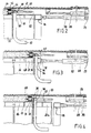
- the distribution system according to FIG. 1 comprises a concrete mixing container 10, a double-acting concrete pump 12, the usual switch valve 14, a delivery line 16 with schematic Illustrated telescopic pipe extension 18 and an annular distribution line 30, which is arranged in a transverse plane of a tunnel and thus essentially at right angles to the longitudinal extent of the delivery line 16 and has a number of branching points 32 arranged at circumferential intervals and which is connected to the delivery line 16 via a pipe loop 39, 40 connected.
- the distribution line 30 lies on a diameter which is larger than the diameter of an inner ring formwork 22 and runs closely adjacent to an end formwork 24 which closes a formwork space between an outer ring formwork 20 and the inner ring formwork 22 to the front.
- the distribution line 30 thus lies in the annular gap 42 between the outer and inner ring formwork and, thanks to the close proximity to the end formwork 24, short, straight branch lines 34 at each branch point 32, which penetrate the end formwork 24, are sufficient.
- the delivery line 16 is extended in the interior of the tunnel beyond the level of the front formwork 24.
- a pipe bend 39 extends around the front edge of a pressure ring 76 and a subsequent connecting pipe 40 bridges the width of an inner formwork segment including the width of the pressure ring, as can be seen in particular from FIG. 2 results. This pipe loop is necessary in order to be able to assemble the next inner formwork ring 22.
- a shut-off device 36 is provided with which the branch line 34 can be shut off.
- the distribution line 30 extends along a circumferential angle of more than 270 ° and at its end is connected via a pipe loop 44, 46, which corresponds to the pipe loop 39, 40 and serves the same purpose, an emptying line 48 which extends parallel to the delivery line 16 and runs back into the tunnel.
- the drain line 48 is connected via a valve 50 to a concrete pushing device 52, which is a holding device 54 for a Has cleaning plug 55.
- a pressurized water pump 56 is connected to the holding device 54.
- a circulation line 58 branches off from the drain line 48 and can be shut off by a valve 51 and leads back into the mixing container 10.
- the shut-off valve 36 has three quick couplings 38, by means of which it is connected to the incoming part 30a of the distribution line 30, the outgoing part 30b and the short straight branch line 34.
- a plug 66 in the form of a piston is slidably mounted, which has a curved front surface 70, which for a constant transition of the concrete flow from the incoming part 30a of the distribution line 30 with deflection by 90 ° in the branch line 34 provides.
- This curved end face 70 of the sealing plug 66 also ensures that the sealing plug 66 is longer in the area of the outgoing part 30b of the distribution line 30 and thus in the area shown in FIG.
- the sealing plug 66 is connected at the rear to a drive cylinder 69, which moves it forward into a closed position in which the sealing plug 66 comes out of the branch line 34 penetrates into the formwork space beyond its mouth 68 and thereby completely fills the branch line 34.
- the plug 66 has a transverse channel 74 which, in the closed position of the plug 66, connects the incoming part 30a to the outgoing part 30b of the distribution line 30.
- the ring line 30 is fastened on both sides of each shut-off device 36 to the front formwork 24 by means of holders 25.
- the distribution line 30 is then filled with concrete, since all the shut-off elements 36 located in between are in the open position.
- the other shut-off elements 36 can now be opened one after the other in any order in order to complete a concrete ring 26.
- the front formwork 24 which is connected to the outer formwork 20, moves.
- the front formwork 24 is partly pushed by the pressure of the pressed-in concrete and partly pulled by a cylinder 28 which is fastened to a frame 29 of the driving head.
- the front formwork 24 has arrived at the front end of an inner formwork ring 22, the concrete ring 26 is finished (FIG. 3).
- the pressure ring 76 is pulled forward by means of cylinder 78 and a new inner formwork ring 22 is mounted (FIG. 4) which is then pressed against the inner formwork by means of the pressure ring 76.
- the concreting process then continues in order to produce a new concrete ring in the area of the annular gap 42.
- valve 51 can first be opened in order to keep the concrete in motion throughout the pipeline system by the concrete pump 12 running slowly.
- the plugs 66 are all in their closed positions.
- the concrete pump 12 is switched off, a slide 80 in the delivery line is closed and a slide 81 in an outlet line connected to the delivery line is opened, after which the pressurized water pump 56 is started, which removes the cleaning plug 55 inserted into the holding device 54 through the emptying line 48, the annular distribution line 30 and the part of the delivery line 16 lying in front of the slide 80, the concrete located in this line system being pushed out in a collecting container 82. Since the cross-sections of all the lines 16, 30, 48 including the valve passages differ only slightly from one another at most, the elastically designed cleaning plug 55 ensures almost complete emptying of the line system, the pressurized water flushing out any concrete residues.
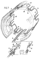
- FIG. 7 to 12 a modification of the distribution system is shown, which differs from the one described above only in that the distribution line 130 does not run directly adjacent to the plane A of the face formwork 24 but at a distance therefrom in a plane B, so that the distribution line 130 in front of the pressure ring 76 runs.
- the distribution line 130 is interrupted for each branch point 32.
- the two interruption ends are connected to one another by means of a pipe loop 84 which extends into the annular gap 42 between the two ring formworks 20, 22 approximately parallel to the tunnel axis up to near the end formwork 24 and in whose apex the shut-off device 36 is arranged.
- a pipe loop 84 which extends into the annular gap 42 between the two ring formworks 20, 22 approximately parallel to the tunnel axis up to near the end formwork 24 and in whose apex the shut-off device 36 is arranged.
- each pipe loop consists of two parallel pipes 84, which extend in the longitudinal direction of the tunnel, and two pipe bends 86, which are connected to the housing of the shut-off device 36 by means of the quick couplings 38.
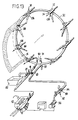
- the distribution system according to FIG. 13 to 18 consists of a distribution line 30, which has no axial pipe loops, because it is arranged in front of the pressure ring 76 and attached to it.
- the two lower ends of the distribution line 30 are connected to one another by a connecting tube, so that there is a circumferentially closed ring line, at the ends of which a shut-off device 90 and 91 is provided.
- Another shut-off element 93 closes the end of the drain line 48.
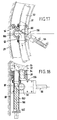
- the displacement axis 162 (FIG. 18) of the sealing plug 166 does not cross the ring axis of the distribution line 30 here, but is offset radially outward by an amount that is equal to the sum of the radii of the branch line 34 and the distribution line 30.
- the inner circumferences of both lines touch each other.
- the pipe section 160 for receiving the sealing plug 166 has an opening 92 through which the branch line 34 communicates with the distribution line 30.
- the closure piece 166 has no through-channel corresponding to the channel 74 in the above-described embodiments.
- the shut-off device 36 has a flat slide 88 which is displaceable in a slot 94 in the valve housing and is actuated by a drive cylinder 96.
- the plane of displacement of the flat slide 88 almost touches the pipe section 160, forms with a radial plane passing through the axis 162 of this pipe section 160
- Distribution line 30 an angle of about 30 ° and closes the outgoing part of the distribution line 30 in its closed position.
- the flat slide valves 88 are preferably located in both ring halves of the distribution line 30 above the respective branches 32 because the distribution system according to FIG. 13 to 18 allows concrete to be fed from below into both halves of the distribution line 30 without having to fill the remaining part of the distribution line 30 with concrete.
- the valves 90, 91 are opened in order to operate the branch line 34 at the bottom right.
- the flat slide 88 are in the closed position. It is then possible to switch to the next higher branch line 34 by closing the valves 90, 91 and opening the flat slide 88 of the valve arranged at the bottom left. After a formwork space is filled with concrete (FIG.
- the pressure ring 76 with the distribution line 30 and face formwork 24 is pulled forward by one formwork width by actuation of the cylinder 78, and since in this embodiment a segmental formwork is used, a new ring made of segment segments 98 is installed and pressed against the remaining tubbing formwork by means of the pressure ring 76 (FIG. 15).
- the cylinder 28 is actuated, which, like the cylinder 78, is supported on a trailing part 100 of the cutting machine in order to advance the outer formwork 20 by a segment width.
- the concrete is then poured into the formwork space 27 as described. The result is shown in FIG. 16.
- the two valves 90, 91 are closed and the valve 93 is opened after the valve 80 in the delivery line 16 has been closed and the valve 81 in the outlet pipe has been opened. Then, after the pressure water pump 56 has started, the cleaning ball 55 can be pressed through the entire line system in the manner already described, in order to insert the concrete column into the Slide out container 82. It is understood that the plugs 166 are in the closed position and the flat slide 88 are in the open position during the emptying of the system. The connecting line between the two valves 90, 91 can also subsequently be flushed when the two flat slides 88 of the two lowest shut-off elements 136 are closed.
- FIGS. 19 and 20 illustrate an annular distribution line 30 with shut-off device 36.
- the distribution line 30 lies within an inner ring formwork 22 and the branch lines 34 extend in the same radial plane in which the distribution line 30 lies radially outwards and into the inner ring formwork 22.
- the pipe loops 39, 40 are omitted. Otherwise, the system does not differ in principle.
- FIG. 21 shows a distribution system which, with regard to the annular distribution line 30 and the shut-off elements 136 of the embodiment according to FIG. 13 corresponds. However, the difference is that the connecting line with the valves between the two lower ends of the distribution line 30 is omitted. This is followed by parallel pipes 17, 19 running in the longitudinal direction, which are connected to the common delivery line 16 by means of a two-way valve 102 and optionally receive concrete from the concrete pump 12. In this simple version, too, both halves of the annular distribution line 30 can be fed from below.
- the two pipes 17, 19 are detached from the distribution line 30 by means of the quick couplings 38 and two hoses 104, 106 are coupled, one of which leads into the collecting container 82 and the other of which is connected to the emptying line 48.
- This embodiment is simpler thanks to the lack of valves, but requires manual intervention to empty the line system.
Landscapes
- Engineering & Computer Science (AREA)
- Structural Engineering (AREA)
- Architecture (AREA)
- Civil Engineering (AREA)
- Mining & Mineral Resources (AREA)
- General Life Sciences & Earth Sciences (AREA)
- Life Sciences & Earth Sciences (AREA)
- Geochemistry & Mineralogy (AREA)
- Geology (AREA)
- Mechanical Engineering (AREA)
- On-Site Construction Work That Accompanies The Preparation And Application Of Concrete (AREA)
- Lining And Supports For Tunnels (AREA)
- Rigid Pipes And Flexible Pipes (AREA)
Claims (17)
Priority Applications (1)
| Application Number | Priority Date | Filing Date | Title |
|---|---|---|---|
| AT89105801T ATE68848T1 (de) | 1988-04-07 | 1989-04-01 | Anlage zur betonverteilung insbesondere fuer den tunnel- und stollenbau. |
Applications Claiming Priority (2)
| Application Number | Priority Date | Filing Date | Title |
|---|---|---|---|
| DE3811585 | 1988-04-07 | ||
| DE3811585A DE3811585A1 (de) | 1988-04-07 | 1988-04-07 | Verfahren und vorrichtung zur verarbeitung von moertel und beton im tunnel- und stollenbau |
Publications (2)
| Publication Number | Publication Date |
|---|---|
| EP0336331A1 EP0336331A1 (fr) | 1989-10-11 |
| EP0336331B1 true EP0336331B1 (fr) | 1991-10-23 |
Family
ID=6351509
Family Applications (1)
| Application Number | Title | Priority Date | Filing Date |
|---|---|---|---|
| EP89105801A Expired - Lifetime EP0336331B1 (fr) | 1988-04-07 | 1989-04-01 | Installation pour la distribution de béton, en particulier pour la construction de tunnels |
Country Status (5)
| Country | Link |
|---|---|
| US (1) | US4892441A (fr) |
| EP (1) | EP0336331B1 (fr) |
| JP (1) | JPH0224496A (fr) |
| AT (1) | ATE68848T1 (fr) |
| DE (2) | DE3811585A1 (fr) |
Families Citing this family (27)
| Publication number | Priority date | Publication date | Assignee | Title |
|---|---|---|---|---|
| US5183356A (en) * | 1988-07-23 | 1993-02-02 | Putzmeister-Werk Maschinenfabrik Gmbh | Method and device for distributing pumpable thick matter into several delivery pipes |
| US5419632A (en) * | 1991-04-02 | 1995-05-30 | Stephens; Patrick J. | Method and apparatus for continuous mixing and injection of foamed cement grout |
| US5141363A (en) * | 1991-04-02 | 1992-08-25 | Stephens Patrick J | Mobile train for backfilling tunnel liners with cement grout |
| EP0890707A1 (fr) * | 1997-07-11 | 1999-01-13 | Heerema Ondergrondse Infrastructuren B.V. | Procédé, système et dispositif pour la construction de parois dans le sol |
| NL1015097C2 (nl) | 2000-05-03 | 2001-12-12 | I T M Ind Tunnelbouw Methode C | Inrichting voor het bouwen van een tunnel. |
| DE10220417A1 (de) * | 2002-05-08 | 2003-11-27 | Bystag Gmbh | Betonfördereinrichtung |
| FR2878890B1 (fr) * | 2004-12-03 | 2007-06-01 | Robert Parra | Dispositif de coffrage pour tunnel |
| WO2008019433A1 (fr) * | 2006-08-14 | 2008-02-21 | Sord Resources Limited | Dispositif d'exploitation minière souterraine |
| ES2338289B8 (es) * | 2007-05-14 | 2011-07-18 | Dragados, S.A. | "maquina para perforar y hormigonar un tunel en continuo". |
| CN102080449B (zh) * | 2009-11-29 | 2013-02-13 | 张改— | 高空输送泥灰机 |
| DE102011007689A1 (de) * | 2011-04-19 | 2012-10-25 | Putzmeister Engineering Gmbh | Anordnung und Verfahren zum Einbringen von Dickstoffmaterial in eine Schalung sowie Steuerarmatur hierfür |
| CN102490256B (zh) * | 2011-12-02 | 2013-09-25 | 赵德臻 | 陶瓷管周向等静压成型装置 |
| WO2015031945A1 (fr) * | 2013-09-04 | 2015-03-12 | Maynard Glen Roy | Appareil de formation de barrière |
| DE102013021889A1 (de) * | 2013-12-23 | 2015-06-25 | Herrenknecht Ag | Verfahren und Vorrichtung zum Verlegen grabenlosen Verlegen von Rohrleitungen |
| CN107620599B (zh) * | 2017-09-13 | 2019-08-23 | 四川皓德斯新材料科技有限公司 | 一种带有顶升装置的隧道二衬堵头模板 |
| EP3543459A1 (fr) * | 2018-03-20 | 2019-09-25 | Kern Tunneltechnik SA | Dispositif et procédé de décoffrage d'un tube de tunnel |
| JP7152327B2 (ja) * | 2019-01-28 | 2022-10-12 | 鹿島建設株式会社 | コンクリート打設装置、型枠ユニット及びコンクリート打設方法 |
| CN110593142A (zh) * | 2019-09-21 | 2019-12-20 | 北京凯新浩达工程技术有限公司 | 一种桥梁修复方法 |
| DE102019127693A1 (de) | 2019-10-15 | 2021-04-15 | Putzmeister Engineering Gmbh | Steuerarmatur, Anordnung und Verfahren zur Herstellung von Betonbauteilen |
| EP3872300A1 (fr) * | 2020-02-27 | 2021-09-01 | Kern Tunneltechnik SA | Dispositif de décoffrage d'un tube de tunnel |
| JP7417477B2 (ja) * | 2020-06-15 | 2024-01-18 | 鹿島建設株式会社 | コンクリート打設装置及びコンクリート打設方法 |
| CN112727098B (zh) * | 2020-12-15 | 2022-05-17 | 中铁隧道集团二处有限公司 | 一种混凝土分料及管路清洗方法 |
| CN113152899B (zh) * | 2021-04-07 | 2023-03-28 | 新疆蓬隆建设工程有限公司 | 一种自动架设溜槽的管道基座浇筑小车 |
| JP7738843B2 (ja) * | 2021-05-24 | 2025-09-16 | 清水建設株式会社 | 覆工コンクリート打込装置および覆工コンクリート打込方法 |
| AT17843U1 (de) * | 2022-02-10 | 2023-05-15 | Oestu Stettin Hoch Und Tiefbau Gmbh | Armatur und Verfahren zum Steuern eines Fluidstromes |
| GB2617615B (en) * | 2022-04-14 | 2024-04-03 | Colin Eddie Consulting Ltd | Tunnel lining method and apparatus |
| JP7796603B2 (ja) * | 2022-07-20 | 2026-01-09 | 戸田建設株式会社 | コンクリート配管切替装置、コンクリート打設システム、及びコンクリート打設方法 |
Family Cites Families (8)
| Publication number | Priority date | Publication date | Assignee | Title |
|---|---|---|---|---|
| US3561223A (en) * | 1968-07-09 | 1971-02-09 | John R Tabor | Tunneling machine with concrete wall forming mechanism |
| US3556116A (en) * | 1968-07-30 | 1971-01-19 | Benjamin F Allen | Apparatus and method for delivering concrete and similar material to a selected point of use |
| DE2023061A1 (de) * | 1970-05-12 | 1971-11-25 | Giulio Pieretti | Pumpe fuer Beton,Dickstoffe,pastose Mischungen und angreifende Substanzen |
| DE2706244C2 (de) * | 1977-02-15 | 1986-01-02 | Gewerkschaft Eisenhütte Westfalia, 4670 Lünen | Messervortriebsverfahren und Messer zum Vortrieb von Tunneln, Stollen u.dgl. unter gleichzeitigem Einbringen einer Betonauskleidung |
| FR2380413A1 (fr) * | 1977-02-15 | 1978-09-08 | Gewerk Eisenhuette Westfalia | Procede et dispositif pour le creusement de tunnels, galeries et cavites analogues, avec pose simultanee d'un revetement en beton |
| DE3506463C1 (de) * | 1985-02-23 | 1986-07-17 | Maschinenfabrik Walter Scheele GmbH & Co KG, 4750 Unna-Massen | Einrichtung zur Betonverteilung in eine Mehrzahl von Fuellstutzen |
| DE3508966A1 (de) * | 1985-03-13 | 1986-09-25 | Hochtief Ag Vorm. Gebr. Helfmann, 4300 Essen | Verfahren und vorrichtung zur herstellung einer tunnelauskleidung aus beton im zuge des tunnelvortriebs mit einer tunnelvortriebsmaschine |
| DE3610118A1 (de) * | 1986-03-26 | 1987-10-01 | Wayss & Freytag Ag | Verfahren zum einbringen von beton in eine schalung zum herstellen einer tunnelauskleidung in ortbeton sowie vorrichtungen zur durchfuehrung des verfahrens |
-
1988
- 1988-04-07 DE DE3811585A patent/DE3811585A1/de not_active Withdrawn
-
1989
- 1989-03-24 US US07/328,248 patent/US4892441A/en not_active Expired - Fee Related
- 1989-04-01 DE DE8989105801T patent/DE58900391D1/de not_active Expired - Lifetime
- 1989-04-01 AT AT89105801T patent/ATE68848T1/de not_active IP Right Cessation
- 1989-04-01 EP EP89105801A patent/EP0336331B1/fr not_active Expired - Lifetime
- 1989-04-07 JP JP1089527A patent/JPH0224496A/ja active Pending
Also Published As
| Publication number | Publication date |
|---|---|
| US4892441A (en) | 1990-01-09 |
| ATE68848T1 (de) | 1991-11-15 |
| EP0336331A1 (fr) | 1989-10-11 |
| JPH0224496A (ja) | 1990-01-26 |
| DE58900391D1 (de) | 1991-11-28 |
| DE3811585A1 (de) | 1989-10-19 |
Similar Documents
| Publication | Publication Date | Title |
|---|---|---|
| EP0336331B1 (fr) | Installation pour la distribution de béton, en particulier pour la construction de tunnels | |
| DE4090849C2 (de) | Verfahren zum Ausbessern eines bestehenden Gasleitungsrohres durch Reparieren von dessen Verbindungsstellen sowie Vorrichtung zum Durchführen des Verfahrens | |
| EP1510269A1 (fr) | Presse radiale pour sertir des corps creux à symétrie de rotation | |
| DE69921585T2 (de) | Wartungsroboter für wäremtauscher und verfahren zu seinem betrieb | |
| DE2826596C2 (de) | Stopfrohranordnung an einer Wurstfüllmaschine | |
| DE2810767A1 (de) | Strahlpumpe | |
| DE102013009967B4 (de) | Mehrfach-Spüldüse für Abwasserkanäle | |
| DE2714124C3 (de) | Vorrichtung zum losbaren Klemmen der Federwelle eines Rohrreinigungsgerates | |
| EP1626854B1 (fr) | Installation servant a traiter des materiaux | |
| DE69011025T2 (de) | Vorrichtung zum automatischen Einsetzen von Dichtungsringen in die Nuten von thermoplastischen Rohrmuffen. | |
| WO1994025695A1 (fr) | Procede permettant de chemiser des canalisations et chariot d'insertion et de retrait pour la mise en ×uvre dudit procede | |
| EP1361335B1 (fr) | Dispositif de distribution de béton | |
| DE102005044967B4 (de) | Absaugeinrichtung für ein Streckwerk | |
| DE3722622C1 (en) | Process for repairing a buried sewer pipe | |
| EP0605364B1 (fr) | Dispositif et procédé notamment pour la mise en état d'un branchement latéral | |
| DE2917897C3 (de) | Drehtrommel-Vakuumfilter | |
| EP4013923A1 (fr) | Raccord de commande, agencement et procédé de production de composants en béton | |
| DE3505309A1 (de) | Druckgas-fadenspleissvorrichtung | |
| DE102019117356A1 (de) | Dickstoffpumpe und Verfahren zum Fördern eines Dickstoffs | |
| DE20309390U1 (de) | Hydraulischer Einzel- und Doppelhubstempel mit Reparatursicherheiten | |
| DE60001048T2 (de) | Vorrichtung zum automatisierten Einbau von Dichtungen in Nutaufnahmen von Muffen an thermoplastischen Kunststoffrohren | |
| DE60009176T2 (de) | Automatische Schwerkraftfüllanlage mit einem Reinigungssystem mit vollständigem Abschaben | |
| DE2408953C2 (de) | Vorrichtung zum Anbohren einer Rohrleitung, insbesondere einer unterirdischen Abwasserleitung | |
| DE20207199U1 (de) | Betonfördereinrichtung | |
| DE2356785B2 (de) | Walzarmatur mit oberen und unteren Walzgutführungen |
Legal Events
| Date | Code | Title | Description |
|---|---|---|---|
| PUAI | Public reference made under article 153(3) epc to a published international application that has entered the european phase |
Free format text: ORIGINAL CODE: 0009012 |
|
| AK | Designated contracting states |
Kind code of ref document: A1 Designated state(s): AT CH DE FR GB IT LI |
|
| 17P | Request for examination filed |
Effective date: 19890926 |
|
| 17Q | First examination report despatched |
Effective date: 19910405 |
|
| GRAA | (expected) grant |
Free format text: ORIGINAL CODE: 0009210 |
|
| AK | Designated contracting states |
Kind code of ref document: B1 Designated state(s): AT CH DE FR GB IT LI |
|
| REF | Corresponds to: |
Ref document number: 68848 Country of ref document: AT Date of ref document: 19911115 Kind code of ref document: T |
|
| REF | Corresponds to: |
Ref document number: 58900391 Country of ref document: DE Date of ref document: 19911128 |
|
| GBT | Gb: translation of ep patent filed (gb section 77(6)(a)/1977) | ||
| ET | Fr: translation filed | ||
| ITF | It: translation for a ep patent filed | ||
| PLBE | No opposition filed within time limit |
Free format text: ORIGINAL CODE: 0009261 |
|
| STAA | Information on the status of an ep patent application or granted ep patent |
Free format text: STATUS: NO OPPOSITION FILED WITHIN TIME LIMIT |
|
| 26N | No opposition filed | ||
| PGFP | Annual fee paid to national office [announced via postgrant information from national office to epo] |
Ref country code: GB Payment date: 19940321 Year of fee payment: 6 |
|
| PGFP | Annual fee paid to national office [announced via postgrant information from national office to epo] |
Ref country code: CH Payment date: 19940324 Year of fee payment: 6 |
|
| PGFP | Annual fee paid to national office [announced via postgrant information from national office to epo] |
Ref country code: FR Payment date: 19940329 Year of fee payment: 6 |
|
| PGFP | Annual fee paid to national office [announced via postgrant information from national office to epo] |
Ref country code: AT Payment date: 19940411 Year of fee payment: 6 |
|
| PGFP | Annual fee paid to national office [announced via postgrant information from national office to epo] |
Ref country code: DE Payment date: 19940623 Year of fee payment: 6 |
|
| PG25 | Lapsed in a contracting state [announced via postgrant information from national office to epo] |
Ref country code: GB Effective date: 19950401 Ref country code: AT Effective date: 19950401 |
|
| PG25 | Lapsed in a contracting state [announced via postgrant information from national office to epo] |
Ref country code: LI Effective date: 19950430 Ref country code: CH Effective date: 19950430 |
|
| GBPC | Gb: european patent ceased through non-payment of renewal fee |
Effective date: 19950401 |
|
| REG | Reference to a national code |
Ref country code: CH Ref legal event code: PL |
|
| PG25 | Lapsed in a contracting state [announced via postgrant information from national office to epo] |
Ref country code: FR Effective date: 19951229 |
|
| PG25 | Lapsed in a contracting state [announced via postgrant information from national office to epo] |
Ref country code: DE Effective date: 19960103 |
|
| REG | Reference to a national code |
Ref country code: FR Ref legal event code: ST |
|
| PG25 | Lapsed in a contracting state [announced via postgrant information from national office to epo] |
Ref country code: IT Free format text: LAPSE BECAUSE OF NON-PAYMENT OF DUE FEES;WARNING: LAPSES OF ITALIAN PATENTS WITH EFFECTIVE DATE BEFORE 2007 MAY HAVE OCCURRED AT ANY TIME BEFORE 2007. THE CORRECT EFFECTIVE DATE MAY BE DIFFERENT FROM THE ONE RECORDED. Effective date: 20050401 |