EP0336611A2 - Dichtungslose modulare Ausgabevorrichtung nach dem Verdrängungsprinzip - Google Patents
Dichtungslose modulare Ausgabevorrichtung nach dem Verdrängungsprinzip Download PDFInfo
- Publication number
- EP0336611A2 EP0336611A2 EP89302904A EP89302904A EP0336611A2 EP 0336611 A2 EP0336611 A2 EP 0336611A2 EP 89302904 A EP89302904 A EP 89302904A EP 89302904 A EP89302904 A EP 89302904A EP 0336611 A2 EP0336611 A2 EP 0336611A2
- Authority
- EP
- European Patent Office
- Prior art keywords
- product
- piston
- chamber
- dispensing
- reservoir
- Prior art date
- Legal status (The legal status is an assumption and is not a legal conclusion. Google has not performed a legal analysis and makes no representation as to the accuracy of the status listed.)
- Granted
Links
- 238000006073 displacement reaction Methods 0.000 title claims abstract description 14
- 239000012530 fluid Substances 0.000 claims abstract description 34
- 230000007246 mechanism Effects 0.000 claims abstract description 14
- 230000002093 peripheral effect Effects 0.000 claims description 15
- 238000007789 sealing Methods 0.000 claims description 10
- 238000010276 construction Methods 0.000 description 22
- 239000000463 material Substances 0.000 description 11
- 239000000853 adhesive Substances 0.000 description 4
- 230000001070 adhesive effect Effects 0.000 description 4
- 230000006835 compression Effects 0.000 description 4
- 238000007906 compression Methods 0.000 description 4
- 230000014759 maintenance of location Effects 0.000 description 4
- 239000000565 sealant Substances 0.000 description 4
- -1 polyethylene Polymers 0.000 description 3
- 239000000919 ceramic Substances 0.000 description 2
- 230000008859 change Effects 0.000 description 2
- 239000007788 liquid Substances 0.000 description 2
- 229920003023 plastic Polymers 0.000 description 2
- 239000004033 plastic Substances 0.000 description 2
- 229910000619 316 stainless steel Inorganic materials 0.000 description 1
- 239000004215 Carbon black (E152) Substances 0.000 description 1
- 229920004943 Delrin® Polymers 0.000 description 1
- 239000004677 Nylon Substances 0.000 description 1
- 239000004698 Polyethylene Substances 0.000 description 1
- 239000004743 Polypropylene Substances 0.000 description 1
- 239000004809 Teflon Substances 0.000 description 1
- 229920006362 Teflon® Polymers 0.000 description 1
- 230000009471 action Effects 0.000 description 1
- 230000002950 deficient Effects 0.000 description 1
- 230000001627 detrimental effect Effects 0.000 description 1
- 230000000694 effects Effects 0.000 description 1
- 229930195733 hydrocarbon Natural products 0.000 description 1
- 150000002430 hydrocarbons Chemical class 0.000 description 1
- 238000002347 injection Methods 0.000 description 1
- 239000007924 injection Substances 0.000 description 1
- 238000004519 manufacturing process Methods 0.000 description 1
- 230000013011 mating Effects 0.000 description 1
- 229910052751 metal Inorganic materials 0.000 description 1
- 239000002184 metal Substances 0.000 description 1
- 150000002739 metals Chemical class 0.000 description 1
- 230000004048 modification Effects 0.000 description 1
- 238000012986 modification Methods 0.000 description 1
- 239000002991 molded plastic Substances 0.000 description 1
- 229920001778 nylon Polymers 0.000 description 1
- 229920000728 polyester Polymers 0.000 description 1
- 229920000573 polyethylene Polymers 0.000 description 1
- 229920000642 polymer Polymers 0.000 description 1
- 229920001155 polypropylene Polymers 0.000 description 1
- 238000009877 rendering Methods 0.000 description 1
- 238000000926 separation method Methods 0.000 description 1
- 239000002002 slurry Substances 0.000 description 1
- 229910001220 stainless steel Inorganic materials 0.000 description 1
- 239000010935 stainless steel Substances 0.000 description 1
Images


Classifications
-
- B—PERFORMING OPERATIONS; TRANSPORTING
- B67—OPENING, CLOSING OR CLEANING BOTTLES, JARS OR SIMILAR CONTAINERS; LIQUID HANDLING
- B67D—DISPENSING, DELIVERING OR TRANSFERRING LIQUIDS, NOT OTHERWISE PROVIDED FOR
- B67D3/00—Apparatus or devices for controlling flow of liquids under gravity from storage containers for dispensing purposes
-
- B—PERFORMING OPERATIONS; TRANSPORTING
- B05—SPRAYING OR ATOMISING IN GENERAL; APPLYING FLUENT MATERIALS TO SURFACES, IN GENERAL
- B05C—APPARATUS FOR APPLYING FLUENT MATERIALS TO SURFACES, IN GENERAL
- B05C11/00—Component parts, details or accessories not specifically provided for in groups B05C1/00 - B05C9/00
- B05C11/10—Storage, supply or control of liquid or other fluent material; Recovery of excess liquid or other fluent material
- B05C11/1002—Means for controlling supply, i.e. flow or pressure, of liquid or other fluent material to the applying apparatus, e.g. valves
- B05C11/1034—Means for controlling supply, i.e. flow or pressure, of liquid or other fluent material to the applying apparatus, e.g. valves specially designed for conducting intermittent application of small quantities, e.g. drops, of coating material
-
- B—PERFORMING OPERATIONS; TRANSPORTING
- B05—SPRAYING OR ATOMISING IN GENERAL; APPLYING FLUENT MATERIALS TO SURFACES, IN GENERAL
- B05B—SPRAYING APPARATUS; ATOMISING APPARATUS; NOZZLES
- B05B1/00—Nozzles, spray heads or other outlets, with or without auxiliary devices such as valves, heating means
- B05B1/30—Nozzles, spray heads or other outlets, with or without auxiliary devices such as valves, heating means designed to control volume of flow, e.g. with adjustable passages
- B05B1/3033—Nozzles, spray heads or other outlets, with or without auxiliary devices such as valves, heating means designed to control volume of flow, e.g. with adjustable passages the control being effected by relative coaxial longitudinal movement of the controlling element and the spray head
- B05B1/304—Nozzles, spray heads or other outlets, with or without auxiliary devices such as valves, heating means designed to control volume of flow, e.g. with adjustable passages the control being effected by relative coaxial longitudinal movement of the controlling element and the spray head the controlling element being a lift valve
- B05B1/3046—Nozzles, spray heads or other outlets, with or without auxiliary devices such as valves, heating means designed to control volume of flow, e.g. with adjustable passages the control being effected by relative coaxial longitudinal movement of the controlling element and the spray head the controlling element being a lift valve the valve element, e.g. a needle, co-operating with a valve seat located downstream of the valve element and its actuating means, generally in the proximity of the outlet orifice
- B05B1/306—Nozzles, spray heads or other outlets, with or without auxiliary devices such as valves, heating means designed to control volume of flow, e.g. with adjustable passages the control being effected by relative coaxial longitudinal movement of the controlling element and the spray head the controlling element being a lift valve the valve element, e.g. a needle, co-operating with a valve seat located downstream of the valve element and its actuating means, generally in the proximity of the outlet orifice the actuating means being a fluid
-
- B—PERFORMING OPERATIONS; TRANSPORTING
- B05—SPRAYING OR ATOMISING IN GENERAL; APPLYING FLUENT MATERIALS TO SURFACES, IN GENERAL
- B05B—SPRAYING APPARATUS; ATOMISING APPARATUS; NOZZLES
- B05B9/00—Spraying apparatus for discharge of liquids or other fluent material, without essentially mixing with gas or vapour
- B05B9/01—Spray pistols, discharge devices
-
- B—PERFORMING OPERATIONS; TRANSPORTING
- B05—SPRAYING OR ATOMISING IN GENERAL; APPLYING FLUENT MATERIALS TO SURFACES, IN GENERAL
- B05C—APPARATUS FOR APPLYING FLUENT MATERIALS TO SURFACES, IN GENERAL
- B05C5/00—Apparatus in which liquid or other fluent material is projected, poured or allowed to flow on to the surface of the work
- B05C5/02—Apparatus in which liquid or other fluent material is projected, poured or allowed to flow on to the surface of the work the liquid or other fluent material being discharged through an outlet orifice by pressure, e.g. from an outlet device in contact or almost in contact, with the work
- B05C5/0225—Apparatus in which liquid or other fluent material is projected, poured or allowed to flow on to the surface of the work the liquid or other fluent material being discharged through an outlet orifice by pressure, e.g. from an outlet device in contact or almost in contact, with the work characterised by flow controlling means, e.g. valves, located proximate the outlet
Definitions
- the present invention relates generally to fluid dispensing mechanisms and, more particularly, to an improved modular positive displacement dispenser system of simplified construction in which the dispenser module does not require seals, particularly sliding seals, or springs for its operation, yet applies precisely controlled quantities of the fluid to a receiving surface.
- Sealants and adhesives are oftentimes difficult to dispense in an accurate and controlled manner. Excessive amounts are wasteful and give a sloppy appearance while insufficient amounts could affect the sealing quality. Moreover, the dispensing should be carried out quickly without compromising on accuracy.
- the fluid When the fluid is a sealant or adhesive material, it subsequently accumulates, then hardens, and thereby has a detrimental effect on the operation of the dispensing mechanism, even to the point of rendering it inoperative.
- An object of the invention is to provide a modular positive displacement apparatus for dispensing precise quantities of a fluid product which includes a dispensing unit, that does not require seals, and an actuator unit.
- a dispensing unit Preferably within the dispensing unit there is provided a ball-type closure mechanism which is actuated by the product itself.
- a deformable diaphragm which isolates the reservoir from the mechanism which actuates the closure to prevent undesirable entry of the product.
- a further object is to provide such an apparatus of modular design in which a self contained actuating unit can be joined with a self contained dispensing unit by way of a quick disconnect construction without loss of fluid wherein both the actuating unit and the dispensing unit may be constructed in a variety of sizes, each size actuating unit being interchangeable with each size dispensing unit. In the same manner, any one of a variety of sizes of dispensing nozzles can also be attached to any of the dispensing units.
- a modular system for dispensing precise quantities of fluid product characterized by: a dispensing unit including closure means movable between an open position for dispensing a defined charge of the product and a closed position; an actuator unit for operating said dispensing unit to dispense said defined charge past said closure means; and mutually engageable locking means on said dispensing unit and on said actuator unit for releasably fixedly attaching a selected one of said dispensing units to said actuator unit.
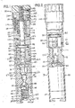
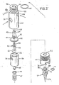
- Figs. 1 through 3 illustrate the modular positive displacement dispensing apparatus 20 embodying the present invention.
- the apparatus 20 comprises a dispensing unit 22, nozzle unit 24 (see Fig. 3), an actuator unit 26, and an adjustment unit 28.
- nozzle unit 24 see Fig. 3
- actuator unit 26 an actuator unit 26
- adjustment unit 28 an adjustment unit 28
- the dispensing unit 22 which includes a cylindrical housing 30 (Fig. 1) with an end member 32 of reduced diameter. While the housing 30 is described and illustrated as being cylindrical and thereby conforms with all of the other units illustrated in Figs. 1 and 2, such shape, while preferred, is not intended to be limiting of the invention.
- An insert 34 is fittingly receivable within the housing 30.
- the insert 34 defines a reservoir 36 capable of receiving pressurized product from a distant source (not shown) via an inlet 39 (Fig. 3) in the housing 30 and an aligned inlet 38 in the insert 34 (Fig. 3).
- the insert 34 is formed at its lower end, viewing Fig.
- a conical closure surface 40 is preferably composed of suitable material compatible with a fluid product to be dispensed.
- suitable materials include, but are not limited to Delrin brand plastic, polyethylene, polypropylene, nylon, polyester, metals including stainless steel and preferably 316 stainless steel, ceramics, and most preferably fluorinated hydrocarbon polymer, for example, Teflon brand plastic.
- the insert 34 is fittingly received in a counterbore 42 formed at the lowermost end (Fig. 1) of the housing 30. It will be appreciated that the housing 30 and insert 34 may be of one piece construction and that they are only described as being separate for ease of fabrication.
- the extreme end of the housing 30, opposite the end member 32, is internally threaded so as to receive a cap member 44 (Fig. 1).
- the cap member 44 has an internal bore 45 with a shoulder 46 therein.
- a compression spring 47 is received in the bore 45 and at one end engages the shoulder 46.
- the spring 47 engages a suitable retainer 48 which, in turn, supports a gate member, preferably in the form of a ball 49, and holds it normally in engagement with the closure surface 40.
- the shoulder 46, spring 47, and retainer 48 all cooperate to firmly hold the ball 49 seated on the closure surface 40.
- a deformable diaphragm 50 which may be composed of any suitable deformable material compatible with the fluid product being dispensed, extends transversely of a longitudinal axis of the housing 30. Such suitable materials may be any of those materials recited above with respect to the valve seat, with the exception of ceramics.
- the outer peripheral regions 52 (Fig. 3) are captured between the insert 34 and a shoulder 53 (Fig. 1) of the housing 30 when the cap member 44 is fully tightened onto the housing.
- the diaphragm 50 has a central aperture 54 which allows it to freely receive a threaded stud 56 extending from a distal portion 58 of an elongated stem member 60.
- a proximal extension 62 of the stem member 60 is threadedly engaged with the stud 56 and when tightened down onto the diaphragm 50, the stem member 60 and the diaphragm 50 operate in a unitary manner.
- the proximal extension 62 is provided with a longitudinal flat 222 (Figs. 1 and 2) which serve as a keyway and prevents rotation of the extension when the flat 222 is engaged by a set screw 224 threaded within housing 30.
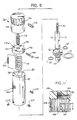
- the distal end of the stem member 60 has a longitudinally extending threaded bore therein to receive a fastener 64 (see especially Figs. 4-7).
- the fastener 64 is slidably received through a diametrically extending bore in a product piston 66 which is, in effect, a ball from which has been removed two opposed spherical segments.
- the piston 66 may be composed of any suitable material compatible with the fluid product being dispensed. Such a suitable material may be any of those materials of which the insert 34 may be composed.
- the piston 66 may have a slight clearance fit with respect to the wall of the chamber 67 or it may have a slight interference fit. It may even use an o-ring to insure a uniform wiping action with the wall of the chamber 67 as it moves. By reason of the cooperative relationship between the product piston 66 and the wall of the chamber 67 there is no need for a check valve between the supply source and the reservoir 36.
- the invention is not to be limited to a closure in the form of the conical surface 40 and the ball 49, but may be of any suitable shape that results in a proper closure of the opening between the reservoir 36 and the nozzle unit 24.
- the conical surface 40 and ball 49 are preferred because they result in substantially a line contact and not an area contact between the mating elements.
- other similar shapes having a spheroidal face may be effectively used and still obtain the benefits of the invention.
- the insert 34 is formed with a chamber 67 intermediate the reservoir 36 and the closure surface 40.
- the chamber 67 is dimensionally smaller than the reservoir 36.
- the chamber is axially aligned with the reservoir 36 such that there is a cone shaped cam surface 67A at the interface between the reservoir 36 and the chamber 67.
- the product piston 66 is movable on the stem member 60 between an inactive position within the reservoir 36 withdrawn from the chamber 67 and an active position sealingly, slidably received within chamber 67.
- the stem member 60 moves downwardly, viewing Fig. 4, it reaches a point at which the outer peripheral surface of the product piston 66 engages the wall of the chamber 67. This initial engagement is illustrated in Fig. 5. Since the product within the reservoir 36 is pressurized, the product being dispensed will also have completely filled the chamber 67. With continued downward movement of the stem member 60, the product piston 66 moves with the stem member, and its outer peripheral surface initially engages the wall of the chamber 67 as illustrated in Fig.5. With continued downward movement of the stem member 60, the product piston 66 moves to an active position well within the chamber 67 which represents its farthest movement of this particular stroke. Such a position is illustrated in Fig. 6. When the product piston moves from the Fig. 5 position to the Fig.
- a particular feature of the invention resides in the construction of the stem member 60 and product piston 66 and their relationship with the chamber 67. Specifically, the construction of the invention compensates for any misalignment that there may be in the various components and permits the apparatus 20 to operate in a completely satisfactory manner nonetheless.
- the stem member 60 is designed to be flexible in directions transverse of its longitudinal axis. With that construction and a contoured outer surface of the product piston 66 as illustrated, in the event the components are misaligned as is indicated in Fig. 7, the outer peripheral surface of the product piston 66 is caused to engage the cam surface 67A which serves to guide the piston therealong until it reaches the Fig. 5 position and is fully centered so as to proceed to the Fig. 6 position.
- cam surface 67A and the outer surface of the product piston 66 are mutually effective to guide the piston into sliding sealing engagement with the inner wall of the chamber 67 even when the longitudinal axis of the stem member is misaligned relative to the longitudinal axis of the insert 34.
- the nozzle unit 24 includes a mounting end 68 which extends through a longitudinal bore 70 formed in the cap member 44.
- An annular groove 72 formed a short distance away from an innermost end of the nozzle unit 24 serves to receive an o-ring seal 74 which assures passage of product, in a manner to be explained, through a hollow needle member 76.
- the cap member 44 is formed with a diametrically extending slot 78 whose purpose is to receivably engage oppositely extending bayonet type extensions 80 integral with the nozzle unit 24.
- the dispensing unit 22 can accommodate, one at a time, a variety of sizes of nozzle units 24.
- a nozzle unit can be removed by twisting it slightly around its longitudinal axis, then pulling it outward of the bore 70.
- a second nozzle unit 24 can then be attached by reversing the operation just described.
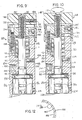
- the actuator unit 26 also as seen in Figs. 1 and 2, and with more detail in Figs. 8-10, includes an elongated cylinder 82 with a longitudinally extending central bore 84 formed in its intermediate regions, a distal counterbore 86, and a proximal counterbore 88. Both counterbores 86 and 88 communicate with and are axially aligned relative to the central bore 84.
- An actuator shaft 90 is slidingly received in the central bore 84 and is integral with a drive piston 92 which is disposed within the counterbore 86.
- the piston 92, and with it actuator shaft 90 is reciprocable along an actuating axis which is the longitudinal axis of the cylinder 82.
- the piston 92 may be fluid operated, preferably pneumatic, although other fluids, including liquids, could be utilized. Indeed, it will be appreciated that the actuator unit 26 could be of a completely different type, for example, an electrically operated solenoid, or a mechanical cam. Also, operation of the actuator unit 26 may be under the control of an appropriate computer (not shown). However, in the instance of the actuator unit 26, o-ring seals 94 and 96 encircle the actuator shaft 90 at locations spaced in opposite directions from the piston 92. The piston 92 itself is also provided with a suitable o-ring seal 98.
- pressurized actuating fluid is introduced to a port 100 whereupon it is caused to flow via a conduit 102 into the counterbore 86 above the piston. Any actuating fluid within the counterbore 86 beneath the piston 92 is then exhausted via a conduit 104 within the end member 32 and a port 106 therein with which it communicates.
- the actuator shaft 90 is prevented from rotating by means of a set screw 108 threadedly engaged with the cylinder 82 and radially disposed therein having an extremity which is positioned proximate to a longitudinal flat 110 (Fig. 8) formed in the shaft which serves as a keyway.
- a compression spring 112 is received in the counterbore 88 and one end rests on a supporting surface 114 thereof.
- the compression spring 112 redundantly, serves to retain the piston 92 in the retracted position illustrated in Fig. 1 when it is in the inactive condition. That is, air or other actuating fluid is normally used to move the piston 92 to the inactive position, but the spring 112 is an added expedient for doing so in the event of a loss of actuating fluid.
- the piston 92 serves to operate the valve mechanism as most specifically represented by the ball 49 operating in conjunction with the closure surface 40.
- the end member 32 of the dispensing unit 22 is slidably received within the distal counterbore 86 of the actuating unit 26.
- An o-ring seal 116 suitably encircles the end member 32 short of its proximal end to assure a sealing relationship between the cylinder 82 and the end member 32.
- an annular groove 122 formed in the outer surface of the end member 32 is aligned with a plurality of circumferentially spaced set screws 124 threadedly engaged with the cylinder 82 and extending radially therethrough.
- the extreme end of the extension 62 is formed with a male T-connector 126 (Fig. 3) which is engageable with a similarly formed female slot 128 (Fig. 8) in the distal end of the shaft 90.
- the dispensing unit 22 is inserted into the actuating unit 26, the former is aligned so that the T-connector 126 is properly received by the slot 128.
- the dispensing unit 22 is rotated 90° so that the T-connector 126 is properly oriented to prevent withdrawal of the stem member 60 from the actuator shaft 90.
- the stem member and the shaft are operable as a unit when they are moved along a longitudinal axis of the apparatus 20.
- the set screws 124 would not be adjusted to engage the annular groove 122 until the T-connector 126 has fully engaged the slot 128.
- the adjustment unit 28 serves to selectively adjust operation of the drive piston 92 so that it moves the product piston 66 to any one of a plurality of active positions from the inactive or withdrawn position. In any of the active positions, the product piston 66 is sealingly, slidably received within the chamber 67.
- a threaded shank 130 is integral with and extends from a proximal end of the actuator shaft 90, that is, from an end distance from the piston 92.
- An internally threaded tubular stud 132 is threadedly engaged with the threaded shank 130.
- the stud 132 is also externally threaded, the external threads being coarser than the internal threads.
- a stroke adjuster nut 134 is threadedly received on the stud 132 and is keyed to the cylinder 82 for rotation therewith about the longitudinal or actuating axis of the apparatus 20.
- the stroke adjuster nut 134 is formed with four bores 136 which are parallel to a longitudinal axis of the cylinder 82 and equally spaced circumferentially of the nut 134.
- the cylinder 82 is formed with a threaded bore 138 adapted to receive a threaded stud 140.
- the axis of the bore 138 is at the same radial distance from the longitudinal axis of the cylinder 82 as each of the bores 136. In any event, the stroke adjuster nut 134 is properly positioned on the stud 132.
- one of the holes 136 is aligned with the threaded bore 138, whereupon the stud 140 is received through the bore 136 and threadedly engaged with the bore 138.
- the nut 134 is held against rotation relative to the cylinder 82, although it has freedom of axial movement relative to the cylinder 82.
- the nut 134 is also formed with a radially directed bore 142 which, together with a compression spring 144 and a ball 146 having a diameter just slightly less than the bore 142, operates as a detent in a manner which will be described shortly.
- a crown member 148 is threadedly engaged with the stud 132.
- the stud extends all the way to the bottom of the threaded bore 150 of the crown member 148.
- a set screw 152 (Fig. 9) is threadedly engaged with a radially directed bore 154 in the crown member, then advanced, until it engages the stud 132. With the set screw 152 thereby engaging the stud 132, the crown member 148 and the stud 132 operate as a unit.
- annular skirt 156 Integral with the crown member 148 is an annular skirt 156 which overlies the outer surface of the cylinder 82. As seen particularly well in Figs. 11 and 12, the inner peripheral surface of the skirt 156 is formed with a plurality of parallel, side-by-side, longitudinally extending grooves 158, each groove having approximately the same radius of curvature as the ball 146. Indeed, the ball 146 engages one of the grooves 158 at a time. By reason of the resiliency of the spring 144, the crown member 148 can be rotated about its longitudinal axis, causing the ball 146 to ride over a ridge 160 intermediate adjoining grooves 158 until it comes to rest in the next groove, and so forth.
- the apparatus 20 might be designed, for example, such that the adjuster nut 134 advances toward or retracts from a terminal surface 162 of the cylinder 82 at the rate of 1/1000th of an inch per click, that is, movement of the ball 146 from one groove 158 to its adjoining groove.
- Figs. 1-7 have consistently illustrated one form and construction of the diaphragm 50, it need not be so limited but may be of a variety of shapes and constructions. However, in each instance the outer peripheral region of the diaphragm is held fixed while the central region is movable in a direction transverse to a general plane of the diaphragm.
- a modified diaphragm 50A is illustrated having its outer peripheral region 164 firmly held between suitable retention members 166, 168. While the stem member 60 fixed to a central region 170 of the diaphragm 50A is free to move in a longitudinal direction, it is subject to the degree of elasticity present in the diaphragm in directions transverse to a plane of the diaphragm. Extreme positions of the diaphragm 50A, one shown in dotted lines, are illustrated in Fig. 14.
- FIG. 15 Another modified diaphragm 50B has its outer peripheral region 172 fixedly held by retention members 174, 176 while its central region 178 is fixed to the stem member 60.
- the diaphragm 50B which is illustrated in Fig. 15 in its relaxed condition, includes a first fold member 180 adjacent the central region 178 and a second fold member 182 adjacent the outer peripheral region 172.
- the fold members 180 and 182 intersect at an annular apex 184 which is of a living hinge construction. As seen in Fig.
- the apex 184 lies out of the plane of the central region 178 and outer peripheral region 172 when the diaphragm 50B assumes its solid line position (Fig. 15).
- the stem member 60 is moved along its longitudinal axis, it will be seen that the diaphragm can take either of the two extreme positions illustrated in Fig. 15 by means of dotted lines. It will be appreciated that the displacement from the norm obtainable with the diaphragm 50B is substantially greater than that obtainable with either the diaphragm 50 or 50A.
- Fig. 16 A variation on the construction of the diaphragm 50B is illustrated in Fig. 16 in which another modified diaphragm 50C is illustrated.
- the diaphragm has an outer peripheral region 186 which is fixed between suitable retention members 188, 190 and a central region 192 which is fixed to the stem member 60.
- a plurality of concentric fold members 194, 196 cooperate with a like plurality of fold members 198, 200.
- Each adjoining pair of fold members defines an annular apex 202, 204, and 206, respectively, each of which is living hinge.
- the diaphragm 50C can be moved to the extreme positions indicated by dotted lines in Fig. 16 in which all of the fold members are movable toward a generally mutually coplanar relationship.
- FIG. 17 Still another construction is illustrated in Fig. 17 in which an outer cylindrical retention member 208 which may be a housing itself or an insert within that housing is formed with an internal annular slot 210 therein.
- the slot 210 is capable of receiving and holding an outer peripheral region 212 of another modification diaphragm 50D whose central region 214 is fixed to the stem member 60.
- FIG. 18 Yet another construction is illustrated in Fig. 18 in which an outer retainer 216 and a modified diaphragm 50E are integral.
- the components may be fabricated, for example, of an injection molded plastic material.
- An outer peripheral region of the diaphragm 50E, in this construction, is integral with the retainer 216 but, again, it has a central region 218 which is fixed to the stem member 60.
- the stem member is movable along its longitudinal axis within defined limits depending upon the degree of elasticity present in the diaphragm.
- the particular fluid to be dispensed which may be, for example, a sealant or adhesive material in the form of a slurry, or otherwise, and may have viscosities of from 1 centipoise to 1,000,000 or more centipoise, is introduced, under pressure, via ports 38 and 39 so as to fill the reservoir 36 and the chamber 67.
- the actuator unit 26 is operated to dispense the product from the dispensing unit 22. Viewing Fig. 1, this is achieved by introducing pressurized fluid, air for example, via the port 100 to the upper side of the piston 92. This moves the actuator shaft 90 downwardly and, with it, the stem member 60.
- Fig. 9 illustrates a positioning of the adjuster nut 134 relative to the terminal surface 162 which will permit only a relatively small stroke by the piston and Fig. 10 illustrates such a relative positioning as will permit a relatively long stroke for the piston.
- the apparatus 20 is of a modular design in that it permits various combinations of actuator units 26, diaphragms, dispensing units 22, and nozzle units 24.
- the dispenser of the invention is considered sealless because the dispensing unit 22 completely lacks the sliding seals of the type which have heretofore customarily been employed in a fluid dispensing apparatus and which typically fail in their operation when the seals fail.
- the diaphragm 50 is the sole component utilized to isolate the actuator unit 26 from the dispensing unit 22. While axial movement is permitted by reason of the deformability of the and its outer peripheral locations to prevent any possibility of the product passing from the reservoir 36 into the mechanism of the actuator unit. Additionally, this construction allows quick change of dispensing units without loss of product. Wear and frictional losses and loss of product are avoided by reason of this construction.
- o-ring seals 94, 96, 98, and 116 are seals within the actuator unit 26 and not directly involved with, or concerned with, the product being dispensed.
- the o-ring seal 74 (Fig. 3) is associated with the nozzle unit 24 and, therefore, also not directly with the dispensing unit 22. In any event, its condition is easily observable and it can be readily removed along with the nozzle unit and replaced if it becomes defective. Furthermore, it is not a dynamic, or sliding type seal, which is the type of seal with which the invention is concerned and serves to replace.
Landscapes
- Engineering & Computer Science (AREA)
- Mechanical Engineering (AREA)
- Coating Apparatus (AREA)
- Containers And Packaging Bodies Having A Special Means To Remove Contents (AREA)
- Closures For Containers (AREA)
- Extraction Or Liquid Replacement (AREA)
- External Artificial Organs (AREA)
- Feeding, Discharge, Calcimining, Fusing, And Gas-Generation Devices (AREA)
- Reciprocating Pumps (AREA)
Priority Applications (2)
| Application Number | Priority Date | Filing Date | Title |
|---|---|---|---|
| AT89302904T ATE86148T1 (de) | 1988-04-04 | 1989-03-23 | Dichtungslose modulare ausgabevorrichtung nach dem verdraengungsprinzip. |
| KR2019970021703U KR0129583Y1 (ko) | 1988-04-04 | 1997-08-08 | 시일이 없는 양변위 모듈식 분배기 |
Applications Claiming Priority (2)
| Application Number | Priority Date | Filing Date | Title |
|---|---|---|---|
| US176875 | 1988-04-04 | ||
| US07/176,875 US4858789A (en) | 1988-04-04 | 1988-04-04 | Sealless modular positive displacement dispenser |
Publications (3)
| Publication Number | Publication Date |
|---|---|
| EP0336611A2 true EP0336611A2 (de) | 1989-10-11 |
| EP0336611A3 EP0336611A3 (en) | 1990-08-29 |
| EP0336611B1 EP0336611B1 (de) | 1993-03-03 |
Family
ID=22646236
Family Applications (1)
| Application Number | Title | Priority Date | Filing Date |
|---|---|---|---|
| EP89302904A Expired - Lifetime EP0336611B1 (de) | 1988-04-04 | 1989-03-23 | Dichtungslose modulare Ausgabevorrichtung nach dem Verdrängungsprinzip |
Country Status (10)
| Country | Link |
|---|---|
| US (1) | US4858789A (de) |
| EP (1) | EP0336611B1 (de) |
| JP (1) | JP2748015B2 (de) |
| KR (1) | KR890015951A (de) |
| AT (1) | ATE86148T1 (de) |
| AU (2) | AU610713B2 (de) |
| BR (1) | BR8901577A (de) |
| CA (1) | CA1337904C (de) |
| DE (1) | DE68905058T2 (de) |
| MX (1) | MX169282B (de) |
Cited By (1)
| Publication number | Priority date | Publication date | Assignee | Title |
|---|---|---|---|---|
| WO2001071293A1 (en) * | 2000-03-21 | 2001-09-27 | Prima Technologies Limited | Multi-barrel dispensing apparatus |
Families Citing this family (10)
| Publication number | Priority date | Publication date | Assignee | Title |
|---|---|---|---|---|
| US5277342A (en) * | 1992-12-11 | 1994-01-11 | Loctite Corporation | Sealless dispensing apparatus |
| US5411350A (en) * | 1993-11-03 | 1995-05-02 | Loctite Corporation | Quick connect/disconnect device, and dispensing apparatus comprising same |
| AUPQ212799A0 (en) * | 1999-08-10 | 1999-09-02 | Hanly, Robert John | Decompressing system for a masticating gun |
| US7552847B2 (en) * | 2003-05-09 | 2009-06-30 | Intellipack | Dispenser mixing module and method of assembling and using same |
| DE102006019364A1 (de) * | 2006-04-21 | 2007-10-25 | Krautzberger Gmbh | Spritzvorrichtung |
| DE102017126307A1 (de) * | 2017-11-09 | 2019-05-09 | Delo Industrie Klebstoffe Gmbh & Co. Kgaa | Dosiervorrichtung sowie Verfahren zum Dosieren von flüssigen Medien |
| CN110064568B (zh) * | 2019-03-27 | 2020-03-27 | 诸暨市和冬水晶有限公司 | 一种水晶点胶装置 |
| ES2906064T3 (es) * | 2019-03-29 | 2022-04-13 | Robatech Ag | Dispositivo para la distribución de un medio capaz de fluir |
| US20210301943A1 (en) * | 2020-03-27 | 2021-09-30 | Illinois Tool Works Inc. | Dispensing unit having fixed flexible diaphragm seal |
| DE102024120802A1 (de) * | 2024-07-22 | 2026-01-22 | Vermes Microdispensing GmbH | Dosierventil mit Getriebe-Feinadjust |
Family Cites Families (14)
| Publication number | Priority date | Publication date | Assignee | Title |
|---|---|---|---|---|
| US2111168A (en) * | 1935-03-04 | 1938-03-15 | Chansor John | Flexible corrugated diaphragm |
| US3022955A (en) * | 1957-01-09 | 1962-02-27 | Elizabeth White Riddell | Applicator |
| US3104986A (en) * | 1960-08-08 | 1963-09-24 | Robert L Goman | Fluid dispensing system |
| US3355112A (en) * | 1964-12-04 | 1967-11-28 | Wald Ind Inc | Bead dispenser for use with apparatus for marking road surfaces |
| US3327900A (en) * | 1965-01-27 | 1967-06-27 | Greiner Scient Corp | Liquid dispensing device |
| US3463363A (en) * | 1967-10-12 | 1969-08-26 | Fusion Inc | Applicator gun |
| US4347806A (en) * | 1980-10-30 | 1982-09-07 | Loctite Corporation | Liquid dispensing apparatus |
| DE3134940C2 (de) * | 1981-09-03 | 1983-12-15 | Grünbeck Wasseraufbereitung GmbH, 8884 Höchstädt | Dosierpumpe |
| US4353325A (en) * | 1981-09-28 | 1982-10-12 | Loctite Corporation | Sealant applying apparatus |
| DE3202189C2 (de) * | 1982-01-25 | 1983-11-24 | Gebrüder Hau Maschinenfabrik GmbH & Co, 6050 Offenbach | Hochdruckdosiervorrichtung, insbesondere zum Ausspritzen einer Polierpaste |
| US4456152A (en) * | 1982-05-03 | 1984-06-26 | Young Don H | Measuring and dispensing apparatus |
| JPS6040445U (ja) * | 1983-08-25 | 1985-03-22 | 金子農機株式会社 | 堆肥製造装置 |
| JPS60126370U (ja) * | 1984-02-01 | 1985-08-26 | 株式会社 山本製作所 | 円筒容器内の粘性物押し出し装置 |
| JPH0332810Y2 (de) * | 1986-06-24 | 1991-07-11 |
-
1988
- 1988-04-04 US US07/176,875 patent/US4858789A/en not_active Expired - Lifetime
-
1989
- 1989-03-23 AT AT89302904T patent/ATE86148T1/de not_active IP Right Cessation
- 1989-03-23 DE DE8989302904T patent/DE68905058T2/de not_active Expired - Fee Related
- 1989-03-23 EP EP89302904A patent/EP0336611B1/de not_active Expired - Lifetime
- 1989-03-29 CA CA000595102A patent/CA1337904C/en not_active Expired - Fee Related
- 1989-04-03 AU AU32395/89A patent/AU610713B2/en not_active Ceased
- 1989-04-04 BR BR898901577A patent/BR8901577A/pt not_active IP Right Cessation
- 1989-04-04 KR KR1019890004406A patent/KR890015951A/ko not_active Withdrawn
- 1989-04-04 MX MX015524A patent/MX169282B/es unknown
- 1989-04-04 JP JP1084146A patent/JP2748015B2/ja not_active Expired - Lifetime
-
1991
- 1991-02-06 AU AU70821/91A patent/AU622065B2/en not_active Ceased
Cited By (1)
| Publication number | Priority date | Publication date | Assignee | Title |
|---|---|---|---|---|
| WO2001071293A1 (en) * | 2000-03-21 | 2001-09-27 | Prima Technologies Limited | Multi-barrel dispensing apparatus |
Also Published As
| Publication number | Publication date |
|---|---|
| MX169282B (es) | 1993-06-28 |
| JP2748015B2 (ja) | 1998-05-06 |
| DE68905058D1 (de) | 1993-04-08 |
| CA1337904C (en) | 1996-01-09 |
| AU622065B2 (en) | 1992-03-26 |
| EP0336611B1 (de) | 1993-03-03 |
| AU610713B2 (en) | 1991-05-23 |
| KR890015951A (ko) | 1989-11-27 |
| DE68905058T2 (de) | 1993-06-17 |
| US4858789A (en) | 1989-08-22 |
| AU3239589A (en) | 1989-10-05 |
| JPH02242769A (ja) | 1990-09-27 |
| AU7082191A (en) | 1991-04-26 |
| EP0336611A3 (en) | 1990-08-29 |
| ATE86148T1 (de) | 1993-03-15 |
| BR8901577A (pt) | 1989-11-21 |
Similar Documents
| Publication | Publication Date | Title |
|---|---|---|
| US4953756A (en) | Modular dispensing system | |
| US5255827A (en) | Sealless modular positive displacement dispenser | |
| US4930669A (en) | Sealless modular dispenser | |
| EP0336611B1 (de) | Dichtungslose modulare Ausgabevorrichtung nach dem Verdrängungsprinzip | |
| US4465212A (en) | Liquid dispensing device | |
| US5887756A (en) | Dispensing gun with valving rod and bellows-type seal | |
| DE69126536T2 (de) | Spender mit einstellbarer dosiermenge | |
| US3982724A (en) | Deformable tube material dispenser | |
| US4579255A (en) | Liquid dispensing device | |
| US5270013A (en) | Reactive fluid mixing head | |
| EP0250922A2 (de) | Spender für Pastenprodukte | |
| CN1942249A (zh) | 具有改进的行程长度校准和流体接头的液体分配阀和方法 | |
| US4893738A (en) | Self-aligning positive displacement dispenser | |
| EP0040068B1 (de) | Abgabevorrichtung für Flüssigkeiten | |
| JP2006175437A (ja) | 改良型シールアセンブリを有する液体吐出装置 | |
| EP0253647A1 (de) | Vorrichtung zum Beimischen eines Zusatzmittels in ein strömendes Fluid | |
| HU209099B (en) | Operating adapter may be placed onto spraying container | |
| US4650099A (en) | Liquid dispensing gun | |
| KR0129583Y1 (ko) | 시일이 없는 양변위 모듈식 분배기 | |
| EP0066017A1 (de) | Flüssigkeitsabgabevorrichtung | |
| JPH0336779Y2 (de) | ||
| KR0129584Y1 (ko) | 모듈식 분배 시스템 | |
| CA1339120C (en) | Sealless modular dispenser | |
| EP0753352B1 (de) | Sprühvorrichtung mit Vordruck-Pumpe und Mengenregelung | |
| GB2140094A (en) | Improvements in hand- operated sprayers |
Legal Events
| Date | Code | Title | Description |
|---|---|---|---|
| PUAI | Public reference made under article 153(3) epc to a published international application that has entered the european phase |
Free format text: ORIGINAL CODE: 0009012 |
|
| AK | Designated contracting states |
Kind code of ref document: A2 Designated state(s): AT BE CH DE ES FR GB GR IT LI LU NL SE |
|
| PUAL | Search report despatched |
Free format text: ORIGINAL CODE: 0009013 |
|
| AK | Designated contracting states |
Kind code of ref document: A3 Designated state(s): AT BE CH DE ES FR GB GR IT LI LU NL SE |
|
| 17P | Request for examination filed |
Effective date: 19901227 |
|
| 17Q | First examination report despatched |
Effective date: 19920121 |
|
| GRAA | (expected) grant |
Free format text: ORIGINAL CODE: 0009210 |
|
| ITF | It: translation for a ep patent filed | ||
| AK | Designated contracting states |
Kind code of ref document: B1 Designated state(s): AT BE CH DE ES FR GB GR IT LI LU NL SE |
|
| PG25 | Lapsed in a contracting state [announced via postgrant information from national office to epo] |
Ref country code: NL Effective date: 19930303 Ref country code: LI Effective date: 19930303 Ref country code: GR Free format text: LAPSE BECAUSE OF FAILURE TO SUBMIT A TRANSLATION OF THE DESCRIPTION OR TO PAY THE FEE WITHIN THE PRESCRIBED TIME-LIMIT Effective date: 19930303 Ref country code: ES Free format text: THE PATENT HAS BEEN ANNULLED BY A DECISION OF A NATIONAL AUTHORITY Effective date: 19930303 Ref country code: CH Effective date: 19930303 Ref country code: BE Effective date: 19930303 Ref country code: AT Effective date: 19930303 |
|
| REF | Corresponds to: |
Ref document number: 86148 Country of ref document: AT Date of ref document: 19930315 Kind code of ref document: T |
|
| PG25 | Lapsed in a contracting state [announced via postgrant information from national office to epo] |
Ref country code: LU Free format text: LAPSE BECAUSE OF NON-PAYMENT OF DUE FEES Effective date: 19930331 |
|
| REF | Corresponds to: |
Ref document number: 68905058 Country of ref document: DE Date of ref document: 19930408 |
|
| ET | Fr: translation filed | ||
| REG | Reference to a national code |
Ref country code: CH Ref legal event code: PL |
|
| NLV1 | Nl: lapsed or annulled due to failure to fulfill the requirements of art. 29p and 29m of the patents act | ||
| PLBE | No opposition filed within time limit |
Free format text: ORIGINAL CODE: 0009261 |
|
| STAA | Information on the status of an ep patent application or granted ep patent |
Free format text: STATUS: NO OPPOSITION FILED WITHIN TIME LIMIT |
|
| 26N | No opposition filed | ||
| ITTA | It: last paid annual fee | ||
| EAL | Se: european patent in force in sweden |
Ref document number: 89302904.1 |
|
| PGFP | Annual fee paid to national office [announced via postgrant information from national office to epo] |
Ref country code: FR Payment date: 20010302 Year of fee payment: 13 |
|
| PGFP | Annual fee paid to national office [announced via postgrant information from national office to epo] |
Ref country code: SE Payment date: 20010306 Year of fee payment: 13 Ref country code: GB Payment date: 20010306 Year of fee payment: 13 |
|
| PGFP | Annual fee paid to national office [announced via postgrant information from national office to epo] |
Ref country code: DE Payment date: 20010307 Year of fee payment: 13 |
|
| REG | Reference to a national code |
Ref country code: GB Ref legal event code: IF02 |
|
| PG25 | Lapsed in a contracting state [announced via postgrant information from national office to epo] |
Ref country code: GB Free format text: LAPSE BECAUSE OF NON-PAYMENT OF DUE FEES Effective date: 20020323 |
|
| PG25 | Lapsed in a contracting state [announced via postgrant information from national office to epo] |
Ref country code: SE Free format text: LAPSE BECAUSE OF NON-PAYMENT OF DUE FEES Effective date: 20020324 |
|
| PG25 | Lapsed in a contracting state [announced via postgrant information from national office to epo] |
Ref country code: DE Free format text: LAPSE BECAUSE OF NON-PAYMENT OF DUE FEES Effective date: 20021001 |
|
| EUG | Se: european patent has lapsed |
Ref document number: 89302904.1 |
|
| GBPC | Gb: european patent ceased through non-payment of renewal fee |
Effective date: 20020323 |
|
| PG25 | Lapsed in a contracting state [announced via postgrant information from national office to epo] |
Ref country code: FR Free format text: LAPSE BECAUSE OF NON-PAYMENT OF DUE FEES Effective date: 20021129 |
|
| REG | Reference to a national code |
Ref country code: FR Ref legal event code: ST |
|
| PG25 | Lapsed in a contracting state [announced via postgrant information from national office to epo] |
Ref country code: IT Free format text: LAPSE BECAUSE OF NON-PAYMENT OF DUE FEES Effective date: 20050323 |