EP0336810A1 - Enceinte comportant un dispositif d'humidification d'air - Google Patents
Enceinte comportant un dispositif d'humidification d'air Download PDFInfo
- Publication number
- EP0336810A1 EP0336810A1 EP89400790A EP89400790A EP0336810A1 EP 0336810 A1 EP0336810 A1 EP 0336810A1 EP 89400790 A EP89400790 A EP 89400790A EP 89400790 A EP89400790 A EP 89400790A EP 0336810 A1 EP0336810 A1 EP 0336810A1
- Authority
- EP
- European Patent Office
- Prior art keywords
- water
- enclosure
- tank
- enclosure according
- container
- Prior art date
- Legal status (The legal status is an assumption and is not a legal conclusion. Google has not performed a legal analysis and makes no representation as to the accuracy of the status listed.)
- Granted
Links
- XLYOFNOQVPJJNP-UHFFFAOYSA-N water Substances O XLYOFNOQVPJJNP-UHFFFAOYSA-N 0.000 claims abstract description 39
- 238000001704 evaporation Methods 0.000 claims description 10
- 230000008020 evaporation Effects 0.000 claims description 10
- 238000010257 thawing Methods 0.000 claims description 6
- 238000010438 heat treatment Methods 0.000 claims description 3
- 230000005494 condensation Effects 0.000 claims 1
- 238000009833 condensation Methods 0.000 claims 1
- 230000032683 aging Effects 0.000 abstract description 4
- 239000000463 material Substances 0.000 abstract description 2
- 238000004321 preservation Methods 0.000 abstract description 2
- 238000001816 cooling Methods 0.000 description 3
- 230000001737 promoting effect Effects 0.000 description 3
- 230000008901 benefit Effects 0.000 description 2
- 230000015572 biosynthetic process Effects 0.000 description 2
- 239000003638 chemical reducing agent Substances 0.000 description 2
- 239000007799 cork Substances 0.000 description 2
- 240000008415 Lactuca sativa Species 0.000 description 1
- 230000000295 complement effect Effects 0.000 description 1
- 230000007423 decrease Effects 0.000 description 1
- 230000018044 dehydration Effects 0.000 description 1
- 238000006297 dehydration reaction Methods 0.000 description 1
- 230000008030 elimination Effects 0.000 description 1
- 238000003379 elimination reaction Methods 0.000 description 1
- 238000009413 insulation Methods 0.000 description 1
- 239000007788 liquid Substances 0.000 description 1
- 239000007791 liquid phase Substances 0.000 description 1
- 238000012423 maintenance Methods 0.000 description 1
- 239000000155 melt Substances 0.000 description 1
- 244000005700 microbiome Species 0.000 description 1
- 230000004048 modification Effects 0.000 description 1
- 238000012986 modification Methods 0.000 description 1
- 230000005855 radiation Effects 0.000 description 1
- 235000012045 salad Nutrition 0.000 description 1
- 230000007704 transition Effects 0.000 description 1
- 238000009834 vaporization Methods 0.000 description 1
- 230000008016 vaporization Effects 0.000 description 1
- 235000013311 vegetables Nutrition 0.000 description 1
- 238000011179 visual inspection Methods 0.000 description 1
Images
Classifications
-
- F—MECHANICAL ENGINEERING; LIGHTING; HEATING; WEAPONS; BLASTING
- F25—REFRIGERATION OR COOLING; COMBINED HEATING AND REFRIGERATION SYSTEMS; HEAT PUMP SYSTEMS; MANUFACTURE OR STORAGE OF ICE; LIQUEFACTION SOLIDIFICATION OF GASES
- F25D—REFRIGERATORS; COLD ROOMS; ICE-BOXES; COOLING OR FREEZING APPARATUS NOT OTHERWISE PROVIDED FOR
- F25D21/00—Defrosting; Preventing frosting; Removing condensed or defrost water
- F25D21/14—Collecting or removing condensed and defrost water; Drip trays
-
- F—MECHANICAL ENGINEERING; LIGHTING; HEATING; WEAPONS; BLASTING
- F25—REFRIGERATION OR COOLING; COMBINED HEATING AND REFRIGERATION SYSTEMS; HEAT PUMP SYSTEMS; MANUFACTURE OR STORAGE OF ICE; LIQUEFACTION SOLIDIFICATION OF GASES
- F25D—REFRIGERATORS; COLD ROOMS; ICE-BOXES; COOLING OR FREEZING APPARATUS NOT OTHERWISE PROVIDED FOR
- F25D17/00—Arrangements for circulating cooling fluids; Arrangements for circulating gas, e.g. air, within refrigerated spaces
- F25D17/04—Arrangements for circulating cooling fluids; Arrangements for circulating gas, e.g. air, within refrigerated spaces for circulating air, e.g. by convection
- F25D17/042—Air treating means within refrigerated spaces
-
- F—MECHANICAL ENGINEERING; LIGHTING; HEATING; WEAPONS; BLASTING
- F25—REFRIGERATION OR COOLING; COMBINED HEATING AND REFRIGERATION SYSTEMS; HEAT PUMP SYSTEMS; MANUFACTURE OR STORAGE OF ICE; LIQUEFACTION SOLIDIFICATION OF GASES
- F25D—REFRIGERATORS; COLD ROOMS; ICE-BOXES; COOLING OR FREEZING APPARATUS NOT OTHERWISE PROVIDED FOR
- F25D2317/00—Details or arrangements for circulating cooling fluids; Details or arrangements for circulating gas, e.g. air, within refrigerated spaces, not provided for in other groups of this subclass
- F25D2317/04—Treating air flowing to refrigeration compartments
- F25D2317/041—Treating air flowing to refrigeration compartments by purification
- F25D2317/0413—Treating air flowing to refrigeration compartments by purification by humidification
-
- F—MECHANICAL ENGINEERING; LIGHTING; HEATING; WEAPONS; BLASTING
- F25—REFRIGERATION OR COOLING; COMBINED HEATING AND REFRIGERATION SYSTEMS; HEAT PUMP SYSTEMS; MANUFACTURE OR STORAGE OF ICE; LIQUEFACTION SOLIDIFICATION OF GASES
- F25D—REFRIGERATORS; COLD ROOMS; ICE-BOXES; COOLING OR FREEZING APPARATUS NOT OTHERWISE PROVIDED FOR
- F25D2321/00—Details or arrangements for defrosting; Preventing frosting; Removing condensed or defrost water, not provided for in other groups of this subclass
- F25D2321/14—Collecting condense or defrost water; Removing condense or defrost water
- F25D2321/141—Removal by evaporation
- F25D2321/1411—Removal by evaporation using compressor heat
-
- F—MECHANICAL ENGINEERING; LIGHTING; HEATING; WEAPONS; BLASTING
- F25—REFRIGERATION OR COOLING; COMBINED HEATING AND REFRIGERATION SYSTEMS; HEAT PUMP SYSTEMS; MANUFACTURE OR STORAGE OF ICE; LIQUEFACTION SOLIDIFICATION OF GASES
- F25D—REFRIGERATORS; COLD ROOMS; ICE-BOXES; COOLING OR FREEZING APPARATUS NOT OTHERWISE PROVIDED FOR
- F25D2321/00—Details or arrangements for defrosting; Preventing frosting; Removing condensed or defrost water, not provided for in other groups of this subclass
- F25D2321/14—Collecting condense or defrost water; Removing condense or defrost water
- F25D2321/144—Collecting condense or defrost water; Removing condense or defrost water characterised by the construction of drip water collection pans
- F25D2321/1441—Collecting condense or defrost water; Removing condense or defrost water characterised by the construction of drip water collection pans inside a refrigerator
-
- F—MECHANICAL ENGINEERING; LIGHTING; HEATING; WEAPONS; BLASTING
- F25—REFRIGERATION OR COOLING; COMBINED HEATING AND REFRIGERATION SYSTEMS; HEAT PUMP SYSTEMS; MANUFACTURE OR STORAGE OF ICE; LIQUEFACTION SOLIDIFICATION OF GASES
- F25D—REFRIGERATORS; COLD ROOMS; ICE-BOXES; COOLING OR FREEZING APPARATUS NOT OTHERWISE PROVIDED FOR
- F25D2321/00—Details or arrangements for defrosting; Preventing frosting; Removing condensed or defrost water, not provided for in other groups of this subclass
- F25D2321/14—Collecting condense or defrost water; Removing condense or defrost water
- F25D2321/145—Collecting condense or defrost water; Removing condense or defrost water characterised by multiple collecting pans
Definitions
- the invention relates mainly to an enclosure comprising an air humidification device.
- Respecting the desired hydrometry may require either to reduce the quantity of water vapor present in the air either by cooling or by desiccation or, as in the case of the present invention, to humidify the air.
- evaporation is favored by maximizing the exchange surfaces and by running water through the enclosure to be humidified.
- the device according to the present invention can be applied to any closed enclosure in particular to enclosures for preserving products as well as to dwellings.
- the invention is particularly applicable to refrigerated enclosures.
- the enclosures intended for storing wine, for example in the bottle require a very high humidity level. This high humidity level notably allows the wine to be isolated from external influences by causing the cork to swell.
- Such enclosures marketed under the name of "Wine Cellar" maintains a constant temperature close to 12 ° allowing good aging of the wine.
- the water is advantageously placed in a tank placed at the bottom of the enclosure.
- This arrangement promotes evaporation and facilitates the leveling of the tank.
- water tends to condense, forming frost on the evaporator and / or pressure reducer.
- the frost goes into the liquid phase.
- the device according to this invention includes guide means allowing the runoff of water and thus promoting its evaporation.
- the guiding device comprises overhangs and regions with a negative slope promoting evaporation by increasing the exchange surface, by the formation of waterfalls and / or by the modification of the flow.
- the main object of the invention is an enclosure as described in claims 1 to 10.
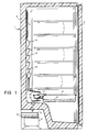
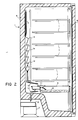
- FIGS. 1 and 2 the same references have been used to designate the same elements.
- the enclosure 1 is a refrigerated enclosure. It has walls 5 providing thermal insulation, a compressor 2 and an evaporator-regulator 4. The hermetic circuits connecting the compress 2 to the evaporator 4 possibly including a heat exchanger on return are not shown in FIG. 1.
- a door 6 gives access to the interior of the enclosure 1.
- the refrigerated enclosure 1 is for example a refrigerator or as illustrated in FIG. 1 a "wine cellar" intended for the conservation and aging of bottles of wine.
- the enclosure of FIG. 1 comprises supports 7 intended to receive the bottles allowing their storage in a horizontal position.
- the door 6 is transparent for allow visual inspection of stored bottles.
- the door 6 filters the radiation harmful to the wine.
- One of the original features of the device according to the present invention consists of the presence of a water tank 8 placed in the lower part of the enclosure 1.
- This tank is intended to maintain a high hydrometry necessary for example for the good behavior of the plugs. in cork ensuring the hermetic closing of the bottles or the good conservation of vegetables and in particular salads in the case of refrigerators.
- the position of the water tank improves the humidification of enclosure 1 because it corresponds to the place where the temperature in the enclosure is the highest as far as it is away from the evaporator 4.
- the fact of placing the tray 8 or a complementary tray in the middle or upper part of the enclosure 1 does not depart from the scope of the present invention.
- a defrosting advantageously automatic, is carried out of evaporator 4.
- the defrosting operation known per se provides water in liquid form. In a refrigerated enclosure of the conventional type, the defrosting water is eliminated outside the enclosure 1.
- the defrosting water is used to humidify the air in the enclosure 1.
- the means 13 for guiding the water comprise overhangs 14 and regions having a negative slope. This increases the surface runoff and causes mini waterfalls promoting evaporation. The mini waterfalls allow the water to evaporate on both sides of the flow. In addition, evaporation is favored by the transition to turbulent water.
- the water which has not evaporated during the journey on the guide means 13 is evacuated outside by, for example a pipe 10 terminating to a first funnel 11 filling a transfer tank which pours through a second funnel 12 into an external reserve 3.
- the tank 3 is heated to allow the evaporation of the water with a view to its elimination.
- the reservoir 3 is placed on the compressor 2 so as to benefit from the supply of calories from the work of the compressor 2.
- the reservoir 3 increases the efficiency of the device by ensuring the cooling of the compressor 3.
- the evacuation of the water 9 towards the outside of the enclosure 1, for example towards the tank 3, makes it possible to add clean water to the tank 8 and to be guaranteed to limit the formation of microorganisms in enclosure 1.
- the device of FIG. 1 requires periodically adding water 9 to the reservoir 8. This can prove to be restrictive in the case, for example of a long absence without supervision of the device of FIG. 1. In such a case may be advantageous, as illustrated in FIG. 2, to add water which has not evaporated during the journey on the means 13 for guiding in the tank 8. In this case, the funnel 11 opens into the tank 8 .
- the funnel 8 can rotate around its axis to allow, depending on the position chosen, the closed circuit operation illustrated in FIG. 2 or operation with the evacuation to an external reservoir 3 of the non-evaporated deicing water, as illustrated in FIG. 1.
- the direct connection of the guide means 13 to the reservoir 8 or to the reservoir 3, for example by a pipe does not depart from the scope of the present invention.
- This hose is either fixed to allow one of the two desired operating modes or it can be placed in the desired position in the tank 8 or the tank 3.
- Evaporation of the defrost water has the additional advantage of cooling the enclosure 1.
- the use of latent heat of vaporization of the defrost water or of the water 9 contained in the tank 8 makes it possible to save energy.
- the invention mainly applies to the humidification of enclosures.
- the invention applies in particular to the humidification of refrigerated enclosures such as, for example, enclosures intended for the storage, preservation and aging of bottled wine.
- the invention also applies to refrigerated enclosures for storing foodstuffs or photosensitive materials such as, for example, photographic film or photosensitive paper.
Landscapes
- Engineering & Computer Science (AREA)
- Chemical & Material Sciences (AREA)
- Combustion & Propulsion (AREA)
- Physics & Mathematics (AREA)
- Mechanical Engineering (AREA)
- Thermal Sciences (AREA)
- General Engineering & Computer Science (AREA)
- Removal Of Water From Condensation And Defrosting (AREA)
- Cold Air Circulating Systems And Constructional Details In Refrigerators (AREA)
- Devices That Are Associated With Refrigeration Equipment (AREA)
Abstract
Description
- L'invention se rapporte principalement à une enceinte comportant un dispositif d'humidification d'air.
- La conservation des divers produits ainsi que le bon fonctionnement de l'appareil exigent de respecter un degré d'hydrométrie. Le respect d'hydrométrie désiré peut imposer soit de diminuer la quantité de vapeur d'eau présente dans l'air soit par un refroidissement ou par une dessiccation soit comme dans le cas de la présente invention, d'humidifier l'air.
- Dans le dispositif selon la présente invention on favorise l'évaporation en maximisant les surfaces d'échange et en effectuant un ruissellement de l'eau dans l'enceinte à humidifier. Le dispositif selon la présente invention peut s'appliquer à toute enceinte fermée notamment aux enceintes pour conservation des produits ainsi qu'aux habitations. L'invention s'applique particulièrement aux enceintes réfrigérées. Parmi les enceintes réfrigérées, les enceintes destinées à conserver le vin par exemple en bouteille demande un très fort taux d'humidité. Ce fort taux d'humidité permet notamment l'isolation du vin des influences extérieures en provoquant un gonflement du bouchon. De telles enceintes commercialisées sous le nom de "Cave à Vin" maintient une température constante voisine de 12° permettant un bon vieillissement du vin.
- Dans le dispositif selon la présente invention, l'eau est avantageusement disposée dans un bac placé en bas de l'enceinte. Cette disposition favorise l'évaporation et facilite la mise à niveau du réservoir. Dans les enceintes fermées réfrigérées l'eau a tendance à se condenser en formant du givre sur l'évaporateur et/ou détendeur. Lors du dégivrage, par exemple par l'utilisation d'une résistance chauffante, le givre passe en phase liquide. Le dispositif selon la présente invention comporte des moyens de guidage permettant le ruissellement de l'eau et ainsi favorisant son évaporation. Avantageusement, le dispositif de guidage comporte des surplombs et des régions à pente négative favorisant l'évaporation par l'augmentation de la surface d'échange, par la formation des cascades et/ou par la modification de l'écoulement.
- Ainsi, dans une enceinte réfrigérée on compense la déshydratation provoquée par la présence de l'élément froid constitué par le détendeur.
- L'invention a principalement pour objet une enceinte telle que décrite dans les revendications 1 à 10.
- L'invention sera mieux comprise au moyen de la description ci-après et des figures annexées données comme des exemples non limitatifs parmi lesquels :
- - la figure 1 est une vue en coupe d'un premier exemple de réalisation du dispositif selon la présente invention ;
- - la figure 2 est une vue en coupe d'un second exemple de réalisation du dispositif selon la présente invention.
- Sur les figures 1 et 2 on a utilisé les mêmes références pour désigner les mêmes éléments.
- Sur la figure 1, on peut voir une enceinte fermée 1 selon la présente invention. Dans l'exemple de réalisation illustré sur la figure 1, l'enceinte 1 est une enceinte réfrigérée. Elle comporte des parois 5 assurant l'isolation thermique, un compresseur 2 et un évaporateur-détendeur 4. Les circuits hermétiques reliant le compressuer 2 à l'évaporateur 4 comprenant au retour éventuellement un échangeur de chaleur ne sont pas représentés sur la figure 1. Une porte 6 donne l'accès à l'intérieur de l'enceinte 1. L'enceinte réfrigérée 1 est par exemple un réfrigérateur ou comme illustrée sur la figure 1 une "cave à vin" destinée à la conservation et au vieillissement des bouteilles de vin. L'enceinte de la figure 1 comporte des supports 7 destinés à recevoir les bouteilles permettant leur stockage en position horizontale. Avantageusement, la porte 6 est transparente pour permettre le contrôle visuel des bouteilles stockées. Avantageusement, la porte 6 filtre les rayonnements nocifs pour le vin.
- Une des originalités du dispositif selon la présente invention consiste en la présence d'un bac 8 à eau 9 placé dans la partie inférieure de l'enceinte 1. Ce bac est destiné à maintenir une hydrométrie élevée nécessaire par exemple à la bonne tenue des bouchons en liège assurant la fermeture hermétique des bouteilles ou à la bonne conservation des légumes et notamment des salades dans le cas des réfrigérateurs.
- La position du bac à eau permet d'améliorer l'humidification de l'enceinte 1 car elle correspond à l'endroit où la température dans l'enceinte est la plus élevée dans la mesure où on est éloigné de l'évaporateur 4. Toutefois, le fait de disposer le bac 8 ou un bac complémentaire dans la partie médiane ou supérieure à l'enceinte 1 ne sort pas du cadre de la présente invention.
- Malheureusement, l'humidité se condense pour former le givre sur l'évaporateur 4. Ce phénomène, d'une part perturbe le bon fonctionnement de l'évaporateur 4 en diminuant les échanges de chaleur entre l'air de l'enceinte 1 et l'évaporateur 4 et d'autre part diminue l'humidité de l'air présent dans l'enceinte 1. Pour le bon fonctionnement de l'enceinte réfrigérée 1 on effectue un dégivrage, avantageusement automatique, de l'évaporateur 4. Par exemple on fait fondre le givre déposé sur l'évaporateur 4 en arrêtant le compresseur 2 et en débitant un courant électrique dans une résistance (non représentée sur la figure 1) solidaire de l'évaporateur. L'opération de dégivrage connue en soi fournit de l'eau sous forme liquide. Dans une enceinte réfrigérée de type classique l'eau de dégivrage est éliminée à l'extérieur de l'enceinte 1. Dans le dispositif selon la présente invention l'eau de dégivrage sert à humidifier l'air de l'enceinte 1. Pour ce faire on a relié des moyens 13 de guidage de l'eau à l'évaporateur 4. Avantageusement, les moyens 13 de guidage d'eau comportent des surplombs 14 et des régions ayant une pente négative. Ainsi on augmente la surface de ruissellement et on provoque des mini chutes d'eau favorisant l'évaporation. Les mini cascades permettent l'évaporation de l'eau sur les deux faces de l'écoulement. De plus, l'évaporation est favorisée par le passage en régime turbulant de l'eau.
- Dans l'exemple de réalisation du dispositif selon la présente invention illustré sur la figure 1 l'eau qui ne s'est pas évaporée lors du trajet sur les moyens 13 de guidage est évacuée à l'extérieur par, par exemple une conduite 10 aboutissant à un premier entonnoir 11 remplissant un réservoir de transfert qui se déverse à travers un second entonnoir 12 dans une réserve extérieure 3. Avantageusement, le réservoir 3 est chauffée pour permettre l'évaporation de l'eau en vue de son élimination. Ainsi, aucun entretien n'est nécessaire pour vider le réservoir 3. Avantageusement, le réservoir 3 est placé sur le compresseur 2 de façon à bénéficier de l'apport de calories provenant du travail du compresseur 2. De plus, le réservoir 3 augmente le rendement du dispositif en assurant le refroidissement du compresseur 3. L'évacuation de l'eau 9 vers l'extérieur de l'enceinte 1, par exemple vers le réservoir 3, permet de rajouter une eau propre dans le réservoir 8 et d'être assuré de limiter la formation de microorganismes dans l'enceinte 1.
- Toutefois, le dispositif de la figure 1 nécessite de rajouter périodiquement de l'eau 9 dans le réservoir 8. Ceci peut s'avérer contraignant dans le cas par exemple de longue absence sans surveillance du dispositif de la figure 1. Dans un tel cas il peut être avantageux, comme illustré sur la figure 2 de rajouter de l'eau qui ne s'est pas évaporée lors du trajet sur les moyens 13 de guidage dans le réservoir 8. Dans ce cas, l'entonnoir 11 débouche dans le réservoir 8.
- Comme on voit les deux modes de réalisation présente des inconvénients. Avantageusement l'entonnoir 8 peut tourner autour de son axe pour permettre selon la position choisie le fonctionnement en circuit fermé illustré sur la figure 2 ou un fonctionnement avec l'évacuation vers un réservoir 3 extérieur, de l'eau de dégivrage non évaporée, comme illustré sur la figure 1. Le raccordement direct des moyens de guidage 13 au réservoir 8 ou au réservoir 3, par exemple par un tuyau ne sort pas du cadre de la présente invention. Ce tuyau est soit fixe pour permettre un des deux modes de fonctionnement désiré soit il peut être placé selon la position désirée dans le réservoir 8 ou le réservoir 3.
- L'évaporation de l'eau de dégivrage présente de plus l'avantage de refroidir l'enceinte 1. L'utilisation de la chaleur latente de vaporisation de l'eau de dégivrage ou de l'eau 9 contenue dans le bac 8 permet de réaliser des économies d'énergie.
- L'invention s'applique principalement à l'humidification des enceintes.
- L'invention s'applique notamment à l'humidification des enceintes réfrigérées comme par exemple les enceintes destinées au stockage, à la conservation et au vieillissement de vin en bouteille. L'invention s'applique aussi aux enceintes réfrigérées de stockage de denrées alimentaires ou des matériaux photosensibles comme par exemple les pellicules photographiques ou le papier photosensible.
Claims (10)
Applications Claiming Priority (2)
| Application Number | Priority Date | Filing Date | Title |
|---|---|---|---|
| FR8803955 | 1988-03-25 | ||
| FR8803955A FR2629185A1 (fr) | 1988-03-25 | 1988-03-25 | Enceinte comportant un dispositif d'humidification d'air |
Publications (2)
| Publication Number | Publication Date |
|---|---|
| EP0336810A1 true EP0336810A1 (fr) | 1989-10-11 |
| EP0336810B1 EP0336810B1 (fr) | 1992-06-03 |
Family
ID=9364655
Family Applications (1)
| Application Number | Title | Priority Date | Filing Date |
|---|---|---|---|
| EP89400790A Expired - Lifetime EP0336810B1 (fr) | 1988-03-25 | 1989-03-21 | Enceinte comportant un dispositif d'humidification d'air |
Country Status (4)
| Country | Link |
|---|---|
| US (1) | US4979377A (fr) |
| EP (1) | EP0336810B1 (fr) |
| DE (1) | DE68901675D1 (fr) |
| FR (1) | FR2629185A1 (fr) |
Cited By (3)
| Publication number | Priority date | Publication date | Assignee | Title |
|---|---|---|---|---|
| WO2007031452A1 (fr) * | 2005-09-12 | 2007-03-22 | BSH Bosch und Siemens Hausgeräte GmbH | Appareil de réfrigération et évaporateur d'eau de dégivrage associé |
| ITAN20100115A1 (it) * | 2010-07-12 | 2012-01-13 | Antonio Merloni Spa In A S | Frigorifero no-frost perfezionato |
| CN106016558A (zh) * | 2016-05-18 | 2016-10-12 | 中山市凯得电器有限公司 | 一种冰箱或酒柜用的加湿器 |
Families Citing this family (27)
| Publication number | Priority date | Publication date | Assignee | Title |
|---|---|---|---|---|
| KR940001574Y1 (ko) * | 1991-08-02 | 1994-03-19 | 삼성전자 주식회사 | 냉장고의 생성수 처리장치 |
| US5590541A (en) * | 1995-01-16 | 1997-01-07 | The Mead Corporation | Barrel-type refrigerator and drain pan |
| US5651259A (en) * | 1995-12-20 | 1997-07-29 | Condenseco, Inc. | Method and apparatus for filling vehicle fluid reservoir |
| FR2814536B1 (fr) | 2000-09-22 | 2005-09-30 | Jean Louis Guillot | Enceinte a temperature regulee pour la conservation de produits notamment des bouteilles de vin |
| US7007496B2 (en) * | 2003-12-30 | 2006-03-07 | Lotte Engineering & Machinery Mfg., Co., Ltd. | Internal temperature difference preventing structure for refrigerator |
| DE202004007066U1 (de) * | 2004-05-04 | 2004-07-01 | BSH Bosch und Siemens Hausgeräte GmbH | Kältegerät mit Kondenswasserverdunstungssystem |
| US7870891B2 (en) | 2004-05-29 | 2011-01-18 | Kilr-Chilr, Llc | Systems, devices and methods for regulating temperatures of tanks, containers and contents therein |
| CN100553526C (zh) * | 2005-04-21 | 2009-10-28 | 海尔集团公司 | 具有湿度控制单元的酒柜 |
| US7228698B2 (en) * | 2005-06-30 | 2007-06-12 | Premark Feg L.L.C. | Refrigeration unit |
| US7685715B2 (en) * | 2006-05-11 | 2010-03-30 | Kilr-Chilr, Llc | Methods for processing the contents of containers and tanks and methods for modifying the processing capabilities of tanks and containers |
| US20080175951A1 (en) | 2007-01-23 | 2008-07-24 | Rule David D | Methods, apparatuses and systems of fermentation |
| US8166872B2 (en) * | 2008-03-12 | 2012-05-01 | Whirlpool Corporation | Modified atmosphere for food preservation |
| US8359874B2 (en) | 2008-04-18 | 2013-01-29 | Whirlpool Corporation | Secondary cooling path in refrigerator |
| TR200806276A1 (tr) * | 2008-08-21 | 2010-03-22 | Vestel Beyaz E�Ya Sanay� Ve T�Caret Anon�M ��Rket�@ | Bir soğutucu |
| TWI432687B (zh) * | 2010-03-01 | 2014-04-01 | Toshiba Kk | 冰箱 |
| JP5624338B2 (ja) * | 2010-03-01 | 2014-11-12 | 株式会社東芝 | 冷蔵庫 |
| DE102010061962A1 (de) * | 2010-11-25 | 2012-05-31 | BSH Bosch und Siemens Hausgeräte GmbH | Kältegerät mit einer Tropfwasser-Sammeleinrichtung und einer Umlenkeinrichtung |
| CN102116552A (zh) * | 2011-03-31 | 2011-07-06 | 合肥美的荣事达电冰箱有限公司 | 冰箱 |
| CN102183116B (zh) * | 2011-05-05 | 2012-11-28 | 合肥美的荣事达电冰箱有限公司 | 风冷式冰箱的冷藏室加湿系统及具有其的风冷式冰箱 |
| CN102349768B (zh) * | 2011-07-17 | 2012-11-07 | 常熟市德尔电器有限公司 | 食品冷冻冷藏展示柜的化霜水引出机构 |
| CN102538336B (zh) * | 2012-02-13 | 2014-12-17 | 合肥美的电冰箱有限公司 | 冰箱 |
| CN104501500A (zh) * | 2014-12-24 | 2015-04-08 | 合肥华凌股份有限公司 | 冰箱 |
| US10935321B2 (en) | 2015-02-04 | 2021-03-02 | Kilr-Chilr, Llc | Energy transfer systems and energy transfer methods |
| US9434918B1 (en) * | 2015-03-26 | 2016-09-06 | Sandya Lakshmi Narasimhan | System for aging beer |
| CN106524633B (zh) * | 2016-12-28 | 2019-08-27 | 青岛海尔股份有限公司 | 一种冰箱 |
| US12228328B2 (en) | 2020-09-24 | 2025-02-18 | Illinois Tool Works Inc. | Refrigerated device with enhanced condensate evaporation |
| CN115468360B (zh) * | 2022-09-23 | 2024-09-24 | 珠海格力电器股份有限公司 | 加湿结构、冰箱及控制方法 |
Citations (2)
| Publication number | Priority date | Publication date | Assignee | Title |
|---|---|---|---|---|
| FR2433319A1 (fr) * | 1978-08-16 | 1980-03-14 | Bordas Robert | Meuble destine a la conservation de produits tels que vin en bouteille, ou autres denrees |
| DE3541334A1 (de) * | 1985-11-22 | 1987-05-27 | Inst Makrobiotik | Klimatisierungsvorrichtung |
Family Cites Families (7)
| Publication number | Priority date | Publication date | Assignee | Title |
|---|---|---|---|---|
| US2089960A (en) * | 1934-11-30 | 1937-08-17 | Gen Motors Corp | Refrigerating apparatus |
| US2085346A (en) * | 1935-02-26 | 1937-06-29 | Carl G Vretman | Air conditioning system for refrigerators |
| US2090416A (en) * | 1935-06-21 | 1937-08-17 | Gen Motors Corp | Refrigerating apparatus |
| US3585811A (en) * | 1969-12-23 | 1971-06-22 | Visual Graphics Corp | Air conditioned storage system |
| US3667249A (en) * | 1970-09-23 | 1972-06-06 | Gen Motors Corp | Refrigerator with ice maker and high humidity compartment |
| JPS5358149A (en) * | 1976-11-04 | 1978-05-25 | Hitachi Ltd | Moisture conditioner |
| CH635190A5 (de) * | 1977-02-03 | 1983-03-15 | Forster Hermann Ag | Verfahren zum kuehllagern und frischhalten von frischprodukten sowie kuehlmoebel zur ausfuehrung des verfahrens. |
-
1988
- 1988-03-25 FR FR8803955A patent/FR2629185A1/fr not_active Withdrawn
-
1989
- 1989-03-21 EP EP89400790A patent/EP0336810B1/fr not_active Expired - Lifetime
- 1989-03-21 US US07/326,605 patent/US4979377A/en not_active Expired - Fee Related
- 1989-03-21 DE DE8989400790T patent/DE68901675D1/de not_active Expired - Lifetime
Patent Citations (2)
| Publication number | Priority date | Publication date | Assignee | Title |
|---|---|---|---|---|
| FR2433319A1 (fr) * | 1978-08-16 | 1980-03-14 | Bordas Robert | Meuble destine a la conservation de produits tels que vin en bouteille, ou autres denrees |
| DE3541334A1 (de) * | 1985-11-22 | 1987-05-27 | Inst Makrobiotik | Klimatisierungsvorrichtung |
Cited By (5)
| Publication number | Priority date | Publication date | Assignee | Title |
|---|---|---|---|---|
| WO2007031452A1 (fr) * | 2005-09-12 | 2007-03-22 | BSH Bosch und Siemens Hausgeräte GmbH | Appareil de réfrigération et évaporateur d'eau de dégivrage associé |
| ITAN20100115A1 (it) * | 2010-07-12 | 2012-01-13 | Antonio Merloni Spa In A S | Frigorifero no-frost perfezionato |
| WO2012007806A1 (fr) * | 2010-07-12 | 2012-01-19 | Antoniomerloni S.P.A. In A.S. | Réfrigérateur amélioré sans formation de givre |
| CN106016558A (zh) * | 2016-05-18 | 2016-10-12 | 中山市凯得电器有限公司 | 一种冰箱或酒柜用的加湿器 |
| CN106016558B (zh) * | 2016-05-18 | 2021-11-23 | 中山市凯腾电器有限公司 | 一种冰箱或酒柜用的加湿器 |
Also Published As
| Publication number | Publication date |
|---|---|
| EP0336810B1 (fr) | 1992-06-03 |
| US4979377A (en) | 1990-12-25 |
| FR2629185A1 (fr) | 1989-09-29 |
| DE68901675D1 (de) | 1992-07-09 |
Similar Documents
| Publication | Publication Date | Title |
|---|---|---|
| EP0336810B1 (fr) | Enceinte comportant un dispositif d'humidification d'air | |
| EP0044248B1 (fr) | Ensemble frigorifique à compartiments à températures différentes | |
| FR2593588A1 (fr) | Machine frigorifique a adsorption | |
| US4355522A (en) | Passive ice freezing-releasing heat pipe | |
| FR2471562A1 (fr) | Dispositif modulaire pour effectuer un chauffage ou un refroidissement a partir de l'energie solaire par un cycle intermittent de pompe a chaleur a adsorption, et appareil compose de tels dispositifs | |
| FR2727247A1 (fr) | Dispositif de refroidissement pour une batterie constituee de plusieurs elements | |
| CN106133464A (zh) | 用于真空冷却饮料的系统和方法 | |
| CH699989B1 (fr) | Installation de chauffage domestique munie d'une pompe à chaleur. | |
| FR2670875A1 (fr) | Chauffe-eau solaire ainsi qu'appareil de refroidissement et de climatisation ou de dessalement de l'eau de mer. | |
| EP1635682B1 (fr) | Condenseur pour appareil de cuisson | |
| CH660072A5 (fr) | Installation de chauffage d'un liquide. | |
| FR2725265A1 (fr) | Dispositif de regulation et de transfert de fluides frigorifiques ou caloriques pour conteneurs de transport | |
| FR2491607A1 (fr) | Procede et dispositif de stockage d'energie thermique a basse temperature et leur application | |
| EP1591734B1 (fr) | Procédé de contrôle du taux d'humidité dans une cave à vin électrodomestique | |
| FR2485706A1 (fr) | Dispositif de chauffage muni d'une pompe thermique | |
| FR2922001A1 (fr) | Installation de chauffage pour la production d'eau chaude sanitaire et d'eau chaude de chauffage,et dispositif utilise dans une telle installation de chauffage. | |
| FR2788677A1 (fr) | Appareil pour amener a temperature les boissons conditionnees | |
| EP0885370B1 (fr) | Chariots mobiles distributeurs de plateaux-repas chauds et froids | |
| FR2672114A1 (fr) | Unites de refrigeration pour enceintes refrigerees et installation de refrigeration utilisant de telles unites. | |
| FR2524126A1 (fr) | Dispositif de stockage de chaleur et source froide pour pompe a chaleur comportant un tel dispositif | |
| BE380895A (fr) | ||
| FR2549586A1 (fr) | Dispositif refrigerateur de boissons ou autres amovible et adaptable a toute armoire refrigerante | |
| FR2743620A1 (fr) | Appareil de refroidissement rapide d'un liquide | |
| BE636166A (fr) | ||
| FR2652150A1 (fr) | Groupe compresseur frigorifique. |
Legal Events
| Date | Code | Title | Description |
|---|---|---|---|
| PUAI | Public reference made under article 153(3) epc to a published international application that has entered the european phase |
Free format text: ORIGINAL CODE: 0009012 |
|
| AK | Designated contracting states |
Kind code of ref document: A1 Designated state(s): BE DE ES GB IT NL SE |
|
| 17P | Request for examination filed |
Effective date: 19900317 |
|
| 17Q | First examination report despatched |
Effective date: 19910205 |
|
| GRAA | (expected) grant |
Free format text: ORIGINAL CODE: 0009210 |
|
| AK | Designated contracting states |
Kind code of ref document: B1 Designated state(s): BE DE ES GB IT NL SE |
|
| PG25 | Lapsed in a contracting state [announced via postgrant information from national office to epo] |
Ref country code: ES Free format text: THE PATENT HAS BEEN ANNULLED BY A DECISION OF A NATIONAL AUTHORITY Effective date: 19920603 Ref country code: DE Effective date: 19920603 |
|
| ITF | It: translation for a ep patent filed | ||
| GBT | Gb: translation of ep patent filed (gb section 77(6)(a)/1977) | ||
| REF | Corresponds to: |
Ref document number: 68901675 Country of ref document: DE Date of ref document: 19920709 |
|
| PG25 | Lapsed in a contracting state [announced via postgrant information from national office to epo] |
Ref country code: GB Effective date: 19930321 |
|
| PG25 | Lapsed in a contracting state [announced via postgrant information from national office to epo] |
Ref country code: SE Effective date: 19930322 |
|
| PG25 | Lapsed in a contracting state [announced via postgrant information from national office to epo] |
Ref country code: BE Effective date: 19930331 |
|
| PLBE | No opposition filed within time limit |
Free format text: ORIGINAL CODE: 0009261 |
|
| STAA | Information on the status of an ep patent application or granted ep patent |
Free format text: STATUS: NO OPPOSITION FILED WITHIN TIME LIMIT |
|
| 26N | No opposition filed | ||
| BERE | Be: lapsed |
Owner name: SOC. D'ELECTROMENAGER DU NORD SELNOR Effective date: 19930331 |
|
| PG25 | Lapsed in a contracting state [announced via postgrant information from national office to epo] |
Ref country code: NL Effective date: 19931001 |
|
| NLV4 | Nl: lapsed or anulled due to non-payment of the annual fee | ||
| GBPC | Gb: european patent ceased through non-payment of renewal fee |
Effective date: 19930321 |
|
| EUG | Se: european patent has lapsed |
Ref document number: 89400790.5 Effective date: 19931008 |
|
| PG25 | Lapsed in a contracting state [announced via postgrant information from national office to epo] |
Ref country code: IT Free format text: LAPSE BECAUSE OF NON-PAYMENT OF DUE FEES;WARNING: LAPSES OF ITALIAN PATENTS WITH EFFECTIVE DATE BEFORE 2007 MAY HAVE OCCURRED AT ANY TIME BEFORE 2007. THE CORRECT EFFECTIVE DATE MAY BE DIFFERENT FROM THE ONE RECORDED. Effective date: 20050321 |