EP0336837A1 - Automatische Sperrvorrichtung für ausgezogene Teleskoprohre - Google Patents
Automatische Sperrvorrichtung für ausgezogene Teleskoprohre Download PDFInfo
- Publication number
- EP0336837A1 EP0336837A1 EP89400931A EP89400931A EP0336837A1 EP 0336837 A1 EP0336837 A1 EP 0336837A1 EP 89400931 A EP89400931 A EP 89400931A EP 89400931 A EP89400931 A EP 89400931A EP 0336837 A1 EP0336837 A1 EP 0336837A1
- Authority
- EP
- European Patent Office
- Prior art keywords
- tube
- ring
- tubes
- rings
- groove
- Prior art date
- Legal status (The legal status is an assumption and is not a legal conclusion. Google has not performed a legal analysis and makes no representation as to the accuracy of the status listed.)
- Granted
Links
- 230000000903 blocking effect Effects 0.000 title description 9
- 230000008602 contraction Effects 0.000 claims abstract description 7
- 238000000605 extraction Methods 0.000 claims 2
- 230000000694 effects Effects 0.000 description 4
- 240000008042 Zea mays Species 0.000 description 3
- 240000000018 Gnetum gnemon Species 0.000 description 2
- 235000008612 Gnetum gnemon Nutrition 0.000 description 2
- 230000006835 compression Effects 0.000 description 2
- 238000007906 compression Methods 0.000 description 2
- 238000013016 damping Methods 0.000 description 2
- 230000000750 progressive effect Effects 0.000 description 2
- 229910000831 Steel Inorganic materials 0.000 description 1
- 229910001234 light alloy Inorganic materials 0.000 description 1
- 238000004519 manufacturing process Methods 0.000 description 1
- 238000000034 method Methods 0.000 description 1
- 230000035515 penetration Effects 0.000 description 1
- 239000010959 steel Substances 0.000 description 1
Images


Classifications
-
- F—MECHANICAL ENGINEERING; LIGHTING; HEATING; WEAPONS; BLASTING
- F16—ENGINEERING ELEMENTS AND UNITS; GENERAL MEASURES FOR PRODUCING AND MAINTAINING EFFECTIVE FUNCTIONING OF MACHINES OR INSTALLATIONS; THERMAL INSULATION IN GENERAL
- F16B—DEVICES FOR FASTENING OR SECURING CONSTRUCTIONAL ELEMENTS OR MACHINE PARTS TOGETHER, e.g. NAILS, BOLTS, CIRCLIPS, CLAMPS, CLIPS OR WEDGES; JOINTS OR JOINTING
- F16B7/00—Connections of rods or tubes, e.g. of non-circular section, mutually, including resilient connections
- F16B7/10—Telescoping systems
- F16B7/105—Telescoping systems locking in discrete positions, e.g. in extreme extended position
Definitions
- the invention relates to a device for automatically locking telescopic tubes in the deployed position, which allows total securing, particularly from the point of view of rigidity, between two successive tubes in their deployed position.
- the sets of deployable telescopic tubes are provided with locking means in the deployed position, which, according to the embodiments, are automatic, but do not ensure total attachment of the tubes, or are manual clamping and do not can therefore only be used for certain applications.
- the subject of the invention is an automatic locking device for telescopic tubes in the deployed position, which allows a total and particularly rigid connection of two successive tubes, which are effective at the end of the deployment of the tubes, and which, in its rest position , is not opposed to the deployment of the tubes, the sliding force of the tubes one inside the other having to remain as low as possible.
- the device according to the invention is characterized in that it comprises, for each set of two telescopic tubes, two rings capable of radial expansion and contraction mounted one around one end of an internal tube and the other inside an external tube at its end through which the internal tube passes, these rings having one an internal frustoconical surface and the other an external frustoconical surface which are conjugated one of the other, so that, in the retracted position of the tubes, the rings are spaced from each other and, in the deployed position of the tubes, the two rings overlap and are in contact by their frustoconical surfaces, being tightened one on the 'other and on the tubes to immobilize them in position.
- this device makes it possible to automatically and gradually dampen the end of the tube deployment movement.
- each ring comprises one or more longitudinal slots facilitating its expansion or its radial contraction.
- each ring is in abutment on a shoulder of the tube with which it is associated.
- each ring is mounted free in translation relative to the associated tube, and comprises at least one projecting radial lug engaged in a circular groove or groove in the tube, which makes it possible to maintain the ring at the desired end of the associated tube.
- This assembly ensures easy sliding of the telescopic tubes with respect to each other, up to the vicinity of their fully deployed position.
- each ring includes locking means in the clamping position, which cooperate in this position with the associated tube. to the other ring.
- the locking means of a ring comprise one or more teeth projecting from the surface of the ring which faces the surface of the tube associated with the other ring, while this tube surface comprises transverse grooves in which engages the aforementioned tooth or teeth when the rings are in the clamping position.
- each tooth can have an asymmetrical profile which corresponds to an asymmetrical profile of the groove, to allow movement of the ring in the direction corresponding to the deployment of the tubes, and to prevent movement of the ring in the opposite direction.
- the blocking means comprise, on the surface of the ring facing the surface of the tube associated with the other ring, an annular groove with an asymmetrical V section comprising an oblique face and a face substantially perpendicular to the axis of the tubes, and balls housed in this groove and coming into contact with the oblique face of the groove and said tube surface.
- each ring opposite the aforementioned frustoconical surface is itself of frustoconical shape with a angle at the top smaller than that of the first frustoconical surface cited, and is applied in the clamping position of the rings on a conjugate frustoconical surface formed on the facing tube surface.
- All these variant embodiments ensure the locking of the tubes in the deployed position, and prohibit the return of the tubes in the retracted position.
- these locking means have the effect of increasing the tightening of the rings between them and on the tubes in the presence of a tensile or compressive force applied to the internal tube.
- the end of the external tube may be formed by a screwed end piece, which is removable to allow access to the rings and their loosening.
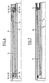
- FIGS. 1 to 3 representing a first embodiment of the invention.
- FIGS. 1 and 2 show two telescopic tubes 10 and 12, which are cylindrical with a circular section, the internal tube 12 being for example movable in axial sliding relative to the external tube 10.
- Each tube 10, 12 is associated with a ring 14, 16 respectively placed in the annular gap between the two tubes 10 and 12.
- the ring 14 associated with the external tube 10 comprises a cylindrical internal surface with circular section, of a diameter slightly greater than the external diameter of the tube 12, and a frustoconical external surface 18 which widens in the direction of the end of the external tube 10 traversed by the internal tube 12.
- This end of the external tube 10 comprises an internal radial flange or shoulder 20 forming a support stop for the ring 14.
- the latter comprises lugs 22 projecting from its external surface, in the vicinity of its end of larger diameter, which are regularly distributed around its periphery and which engage in a groove or annular groove 24 of the internal surface of the tube 10, adjacent to the abutment flange 20, to hold the ring 14 at the end of the tube 10 which is crossed by the internal tube 12.
- Each lug 22 can be formed at the end d 'a longitudinal finger 26 of the ring, elastically deformable.
- the ring 14 must itself be capable of expansion and / or radial contraction and for this purpose comprises longitudinal slots 28 extending alternately from one end of the ring to the vicinity of its opposite end, as shown in figure 3.
- the ring 16 associated with the inner tube 12 has a shape combined with that of the ring 14 associated with the tube 10, that is to say that the ring 16 has a cylindrical outer surface with circular section, having a diameter slightly less than the diameter internal of the tube 10, and a frustoconical inner surface 30 combined with the frustoconical surface 18 of the ring 14.
- the end of the tube 12, located inside the tube 10, includes a rim or an external radial shoulder 32, forming a bearing stop for the ring 16.
- the latter is held on this end of the tube 12 by lugs 34 formed radially projecting inwards on its internal surface, and which engage in an annular groove or groove 36 in the external surface of the tube 12.
- the lugs 34 of the ring 16 correspond to the lugs 22 of the ring 14 and can be formed at the end of elastically deformable fingers 38 of the ring 16.
- the ring 16 is capable of expansion and / or of radial contraction and advantageously comprises longitudinal slots similar to the slots 28 of the ring 14.
- the device operates as follows:
- the tubes 10 and 12 are fitted with rings 14 and 16 similar to those shown in FIGS. 1 and 2, but which also include locking means in the clamping position, to prevent retraction of the tube 12 from the inside the tube 10 and increase the tightening when a longitudinal traction or compression is applied to the tube 12.
- these blocking means comprise teeth 42 projecting from the cylindrical external surface of the ring 16, carried by elastically deformable fingers 44 at the end of the ring 16 turned to the side of the abutment rim 32 of the tube 12.
- the deformable fingers 44 are defined, as can be seen in FIG. 5, between two longitudinal slots 46 of the ring 16.
- the teeth 42 can each be formed by a piece of steel 48 attached to the free end of the corresponding deformable finger 44.
- the teeth 42 of the ring 16 are intended to engage in annular grooves 50 of corresponding shape of the internal cylindrical surface of the tube 10.
- 4 to 5 adjacent grooves 50 can be provided, while the teeth 42 may be six in number, regularly distributed over the periphery of the ring 16, two diametrically opposed teeth 42 being offset longitudinally, one with respect to to the other by a fraction of a step (distance separating two consecutive grooves 50) to ensure maximum penetration of at least some of the teeth 42 in the grooves 50 despite small variations in position of the ring 16 relative to the tube 10 in the deployed state of the telescopic tubes.
- the other ring 14 comprises, at its end adjacent to the annular rim 20 of the tube 10, teeth formed projecting from its internal cylindrical surface and intended to penetrate into annular grooves 52 of the external surface of the tube 12.
- the teeth 42 and the grooves 50 may have an asymmetrical V section, with a rear face substantially perpendicular to the axis of the tubes and a front face inclined obliquely to this axis, so that the ring 16 can be moved relative to the tube 10 in the direction of deployment of the tube 12, but cannot be moved in the opposite direction.
- the teeth of the ring 14 and the grooves 52 of the outer surface of the tube 12 will have a front face substantially perpendicular to the axis of the tubes and a rear face inclined obliquely.
- the end of the tube 10 can be formed by a screwable tip 54 axially crossed by the tube 12.
- the bottom of this tip forms the abutment edge of the ring 14.
- the end 32 of the tube 12 is formed by a screwed end piece, which is unscrewed for loosening the rings.
- the blocking means consist of a ball ring, associated with each of the clamping rings 14, 16.
- the ring 56 with balls 58 associated with the front end of the clamping ring 14 surrounds the internal tube 12 and understands on its internal surface an annular groove for receiving the balls 58 which is defined by a front face 60 substantially perpendicular to the axis of the two tubes and a rear face or a frustoconical bottom 62 whose diameter tapers towards the clamping ring 14
- An elastically deformable O-ring 64 is placed in the bottom of this groove, to hold the balls 58 in abutment on the frustoconical face 62 on the one hand and on the external surface of the tube 12 on the other hand.
- the clamping ring 16 is associated at its rear end with a ring 66 whose external surface comprises a groove for receiving balls 58 and is defined by a rear face 68 substantially perpendicular to the axis of the tubes and a face or tapered bottom 70, the diameter of which tapers in the direction of the ring 16.
- An O-ring 64 received at the bottom of this groove keeps the balls 68 in abutment on the tapered face 70 on the one hand, and on the internal surface of the tube 10 on the other hand.
- the inclinations of the frustoconical faces 62 and 70 of the rings 56 and 66 are such, relative to the direction of deployment of the tube 12, that they allow the deployment of this tube but prevent its return inside the tube 10 by wedging the balls between the rings and the tubes.
- the end of the tube 10 is formed by a screwed end piece 54, which can be unscrewed to take out the assembly from the tube 12 and the rings 14 and 16.
- the ring 14 associated with the outer tube 10 is substantially identical to the ring 14 of FIGS. 1 and 2, but its internal surface, instead of being cylindrical, is slightly frustoconical, its diameter widening towards the front, towards the free end of the tube 10 traversed by the internal tube 12.
- the external surface of the internal tube 12, which is in contact with the internal surface of the ring 14 in the deployed position of the tube 12, is it also slightly frustoconical, by being conjugated with the internal surface of the ring 14.
- the external surface of the ring 16 associated with the internal tube 12 instead of being cylindrical, is slightly frustoconical, its diameter widening towards the front, that is to say in the direction of the free end of the tube 10 traversed by the internal tube 12.
- the internal surface of the tube 10, which is in contact with the external surface of the ring 16, is also frustoconical, being conjugated with the external surface of the ring 16.
- the end of the tube 10 is formed by a targeted sleeve 72 which it suffices to dismount to extract the ring 14 and allow the return of the tube 12 inside the tube 10.
- This taper can be for example of the order of 1.25%, while the taper of the outer surface of the ring 14 and the inner surface of the ring 16 is of the order of 5%.
- the screwed end piece 72 may be replaced by the end piece 54 of FIG. 6, comprising the annular groove or groove in which the pins 22 of the ring 14 engage. , that these pins will remain engaged in this groove when the rings are tightened and that the groove comprises, for example, a helical part relative to the axis of the tubes.
- the ring 14 is automatically extracted, by means of its lugs engaged in said groove.
- the ring 16 is held in place by its lugs 34 engaged in the groove 36 of the tube 12.
- the two rings 14 and 16 are made for example of light alloy.
- the device according to the invention allows rigid blocking of the tubes in the deployed position at the end of deployment, this blocking being maintained and reinforced when an external force is applied to the tubes, either in the direction of deployment or in the opposite direction.
- the force that must be applied to the tube 12 to make it slide relative to the tube 10 remains low, the end of the deployment stroke being automatically damped.
- the embodiment of FIG. 7 allows a progressive blocking of the tubes 10 and 12, as well as an automatic adjustment of the dimensional tolerances due to various causes (manufacturing tolerances, dimensional variations caused by a temperature variation, variation of the deployment efforts).
Landscapes
- Engineering & Computer Science (AREA)
- General Engineering & Computer Science (AREA)
- Mechanical Engineering (AREA)
- Mutual Connection Of Rods And Tubes (AREA)
- Clamps And Clips (AREA)
- Steering Controls (AREA)
Priority Applications (1)
| Application Number | Priority Date | Filing Date | Title |
|---|---|---|---|
| AT89400931T ATE78560T1 (de) | 1988-04-05 | 1989-04-05 | Automatische sperrvorrichtung fuer ausgezogene teleskoprohre. |
Applications Claiming Priority (2)
| Application Number | Priority Date | Filing Date | Title |
|---|---|---|---|
| FR8804458 | 1988-04-05 | ||
| FR8804458A FR2629530B1 (fr) | 1988-04-05 | 1988-04-05 | Dispositif de blocage automatique de tubes telescopiques en position deployee |
Publications (2)
| Publication Number | Publication Date |
|---|---|
| EP0336837A1 true EP0336837A1 (de) | 1989-10-11 |
| EP0336837B1 EP0336837B1 (de) | 1992-07-22 |
Family
ID=9364953
Family Applications (1)
| Application Number | Title | Priority Date | Filing Date |
|---|---|---|---|
| EP89400931A Expired - Lifetime EP0336837B1 (de) | 1988-04-05 | 1989-04-05 | Automatische Sperrvorrichtung für ausgezogene Teleskoprohre |
Country Status (6)
| Country | Link |
|---|---|
| EP (1) | EP0336837B1 (de) |
| AT (1) | ATE78560T1 (de) |
| DE (1) | DE68902162T2 (de) |
| ES (1) | ES2034667T3 (de) |
| FR (1) | FR2629530B1 (de) |
| GR (1) | GR3005969T3 (de) |
Cited By (7)
| Publication number | Priority date | Publication date | Assignee | Title |
|---|---|---|---|---|
| US5155917A (en) * | 1991-05-10 | 1992-10-20 | Nursing Knowledge, Inc. | Pocket sized telescoping level apparatus |
| US6520192B1 (en) * | 2001-11-14 | 2003-02-18 | Albert Chong-Jen Lo | Extensible positioning device of the shank of an umbrella |
| WO2003033392A3 (en) * | 2001-10-12 | 2003-10-02 | David J Higgins | Extensible column |
| US8464391B2 (en) | 2007-04-03 | 2013-06-18 | Diversey, Inc. | Mop head fixation device and method |
| USD719712S1 (en) | 2012-09-07 | 2014-12-16 | Diversey, Inc. | Floor maintenance tool |
| WO2019229022A1 (fr) * | 2018-05-29 | 2019-12-05 | Arianegroup Sas | Dispositif porteur déployable pour équipement de satellite |
| FR3081842A1 (fr) * | 2018-05-29 | 2019-12-06 | Arianegroup Sas | Moyens de verrouillage et de retenue de segments de dispositif porteur deployable et dispositif porteur deployable les comprenant |
Citations (2)
| Publication number | Priority date | Publication date | Assignee | Title |
|---|---|---|---|---|
| FR418616A (fr) * | 1909-09-06 | 1910-12-14 | Wilhelm Kenngott | Pied-support tubulaire télescopantpour appareils photographiques et autres applications |
| DE3204977A1 (de) * | 1981-02-13 | 1982-09-09 | Exel Oy, 00620 Helsinki | Teleskoprohr und verfahren zu dessen herstellung |
-
1988
- 1988-04-05 FR FR8804458A patent/FR2629530B1/fr not_active Expired - Lifetime
-
1989
- 1989-04-05 ES ES198989400931T patent/ES2034667T3/es not_active Expired - Lifetime
- 1989-04-05 AT AT89400931T patent/ATE78560T1/de not_active IP Right Cessation
- 1989-04-05 DE DE8989400931T patent/DE68902162T2/de not_active Expired - Fee Related
- 1989-04-05 EP EP89400931A patent/EP0336837B1/de not_active Expired - Lifetime
-
1992
- 1992-10-12 GR GR920402292T patent/GR3005969T3/el unknown
Patent Citations (2)
| Publication number | Priority date | Publication date | Assignee | Title |
|---|---|---|---|---|
| FR418616A (fr) * | 1909-09-06 | 1910-12-14 | Wilhelm Kenngott | Pied-support tubulaire télescopantpour appareils photographiques et autres applications |
| DE3204977A1 (de) * | 1981-02-13 | 1982-09-09 | Exel Oy, 00620 Helsinki | Teleskoprohr und verfahren zu dessen herstellung |
Cited By (7)
| Publication number | Priority date | Publication date | Assignee | Title |
|---|---|---|---|---|
| US5155917A (en) * | 1991-05-10 | 1992-10-20 | Nursing Knowledge, Inc. | Pocket sized telescoping level apparatus |
| WO2003033392A3 (en) * | 2001-10-12 | 2003-10-02 | David J Higgins | Extensible column |
| US6520192B1 (en) * | 2001-11-14 | 2003-02-18 | Albert Chong-Jen Lo | Extensible positioning device of the shank of an umbrella |
| US8464391B2 (en) | 2007-04-03 | 2013-06-18 | Diversey, Inc. | Mop head fixation device and method |
| USD719712S1 (en) | 2012-09-07 | 2014-12-16 | Diversey, Inc. | Floor maintenance tool |
| WO2019229022A1 (fr) * | 2018-05-29 | 2019-12-05 | Arianegroup Sas | Dispositif porteur déployable pour équipement de satellite |
| FR3081842A1 (fr) * | 2018-05-29 | 2019-12-06 | Arianegroup Sas | Moyens de verrouillage et de retenue de segments de dispositif porteur deployable et dispositif porteur deployable les comprenant |
Also Published As
| Publication number | Publication date |
|---|---|
| GR3005969T3 (de) | 1993-06-07 |
| EP0336837B1 (de) | 1992-07-22 |
| DE68902162T2 (de) | 1993-02-25 |
| FR2629530B1 (fr) | 1990-07-06 |
| ATE78560T1 (de) | 1992-08-15 |
| ES2034667T3 (es) | 1993-04-01 |
| FR2629530A1 (fr) | 1989-10-06 |
| DE68902162D1 (de) | 1992-08-27 |
Similar Documents
| Publication | Publication Date | Title |
|---|---|---|
| EP0586409B1 (de) | Teleskopische rillenrohranordnung | |
| EP0300890B1 (de) | Schnellkupplung zwischen zwei Wellen oder dergleichen | |
| EP0743053B1 (de) | Sicherheits- und Kontrollvorrichtung der Verriegelung einer Radnabe, insbesondere für Rollstuhl | |
| EP0660203A1 (de) | Uhrengehäuse | |
| EP1314856A1 (de) | Vorrichtung zur Sicherung von Laufschaufeln in einer Nut einer Rotorscheibe | |
| EP0665401A1 (de) | Schnellverbindung | |
| WO1998043010A1 (fr) | Collier de serrage pour le raccordement de deux tubes | |
| EP0336837B1 (de) | Automatische Sperrvorrichtung für ausgezogene Teleskoprohre | |
| EP0224393A1 (de) | Trennbarer Zusammenbau eines ein Entriegelungselement tragenden Kupplungsausrücklagers, insbesondere für Kraftfahrzeuge | |
| EP0192081B1 (de) | Zugkraftbetätigtes Kupplungslager | |
| EP2922664B1 (de) | Einführkonus für einen kolben mit seinen segmenten in einem zylinder eines fahrzeugmotors | |
| EP0455558A1 (de) | Vorrichtung zum zeitweiligen Festhalten einer Achse in einem Körper, insbesondere Lenksäulenummantelung | |
| EP1807648A1 (de) | Segmentierter klemmring und entsprechende anordnung und befestigungsverfahren | |
| FR2975323A1 (fr) | Dispositif pour l'extraction de bague | |
| EP0539253B1 (de) | Scheibenbremse | |
| FR2960927A1 (fr) | Attache volante de support et de fixation d'une structure sur une paroi, munie d'un adaptateur | |
| FR2755064A1 (fr) | Procede de demontage-remontage d'un moyeu et d'un roulement du demi-train d'un vehicule et outillage pour sa mise en oeuvre | |
| EP0300883A1 (de) | Schnellkupplung zwischen zwei ein Drehmoment übertragenden Elementen | |
| EP0911605B1 (de) | Verbesserung eines zweiteiligen Grenzsteines | |
| FR2607201A1 (fr) | Dispositif de fixation sur fut filete ou annele | |
| EP0307327A1 (de) | Schraubverbindungensvorrichtung für zwei Elemente mit der Möglichkeit den Abstand dazwischen einzustellen | |
| EP0744588B1 (de) | Vorrichtung zur Herstellung einer abnehmbaren Verbindung zwischen einem Verschluss und einer Wiege eines Geschützes | |
| FR2717437A1 (fr) | Ensemble de colonne de direction réglable en position notamment pour véhicule automobile. | |
| EP0625453A1 (de) | Gelenk für Schwenkbügel eines Scheibenwischers | |
| EP0923165B1 (de) | Unverlierbare Vorrichtung für Verankerungshülse einer Leitung |
Legal Events
| Date | Code | Title | Description |
|---|---|---|---|
| PUAI | Public reference made under article 153(3) epc to a published international application that has entered the european phase |
Free format text: ORIGINAL CODE: 0009012 |
|
| AK | Designated contracting states |
Kind code of ref document: A1 Designated state(s): AT BE CH DE ES FR GB GR IT LI LU NL SE |
|
| 17P | Request for examination filed |
Effective date: 19900314 |
|
| 17Q | First examination report despatched |
Effective date: 19910307 |
|
| GRAA | (expected) grant |
Free format text: ORIGINAL CODE: 0009210 |
|
| AK | Designated contracting states |
Kind code of ref document: B1 Designated state(s): AT BE CH DE ES FR GB GR IT LI LU NL SE |
|
| REF | Corresponds to: |
Ref document number: 78560 Country of ref document: AT Date of ref document: 19920815 Kind code of ref document: T |
|
| REF | Corresponds to: |
Ref document number: 68902162 Country of ref document: DE Date of ref document: 19920827 |
|
| ITF | It: translation for a ep patent filed | ||
| GBT | Gb: translation of ep patent filed (gb section 77(6)(a)/1977) | ||
| REG | Reference to a national code |
Ref country code: GR Ref legal event code: FG4A Free format text: 3005969 |
|
| REG | Reference to a national code |
Ref country code: ES Ref legal event code: FG2A Ref document number: 2034667 Country of ref document: ES Kind code of ref document: T3 |
|
| PLBE | No opposition filed within time limit |
Free format text: ORIGINAL CODE: 0009261 |
|
| STAA | Information on the status of an ep patent application or granted ep patent |
Free format text: STATUS: NO OPPOSITION FILED WITHIN TIME LIMIT |
|
| 26N | No opposition filed | ||
| PGFP | Annual fee paid to national office [announced via postgrant information from national office to epo] |
Ref country code: CH Payment date: 19940304 Year of fee payment: 6 |
|
| PGFP | Annual fee paid to national office [announced via postgrant information from national office to epo] |
Ref country code: GR Payment date: 19940311 Year of fee payment: 6 |
|
| PGFP | Annual fee paid to national office [announced via postgrant information from national office to epo] |
Ref country code: BE Payment date: 19940317 Year of fee payment: 6 |
|
| PGFP | Annual fee paid to national office [announced via postgrant information from national office to epo] |
Ref country code: DE Payment date: 19940328 Year of fee payment: 6 |
|
| PGFP | Annual fee paid to national office [announced via postgrant information from national office to epo] |
Ref country code: SE Payment date: 19940330 Year of fee payment: 6 |
|
| PGFP | Annual fee paid to national office [announced via postgrant information from national office to epo] |
Ref country code: LU Payment date: 19940331 Year of fee payment: 6 Ref country code: GB Payment date: 19940331 Year of fee payment: 6 |
|
| PGFP | Annual fee paid to national office [announced via postgrant information from national office to epo] |
Ref country code: ES Payment date: 19940412 Year of fee payment: 6 |
|
| PGFP | Annual fee paid to national office [announced via postgrant information from national office to epo] |
Ref country code: NL Payment date: 19940430 Year of fee payment: 6 Ref country code: AT Payment date: 19940430 Year of fee payment: 6 |
|
| EPTA | Lu: last paid annual fee | ||
| EAL | Se: european patent in force in sweden |
Ref document number: 89400931.5 |
|
| PG25 | Lapsed in a contracting state [announced via postgrant information from national office to epo] |
Ref country code: LU Free format text: LAPSE BECAUSE OF NON-PAYMENT OF DUE FEES Effective date: 19950405 Ref country code: GB Effective date: 19950405 Ref country code: AT Effective date: 19950405 |
|
| PG25 | Lapsed in a contracting state [announced via postgrant information from national office to epo] |
Ref country code: SE Effective date: 19950406 Ref country code: ES Free format text: LAPSE BECAUSE OF NON-PAYMENT OF DUE FEES Effective date: 19950406 |
|
| PG25 | Lapsed in a contracting state [announced via postgrant information from national office to epo] |
Ref country code: LI Effective date: 19950430 Ref country code: CH Effective date: 19950430 Ref country code: BE Effective date: 19950430 |
|
| BERE | Be: lapsed |
Owner name: BERTIN & CIE Effective date: 19950430 |
|
| PG25 | Lapsed in a contracting state [announced via postgrant information from national office to epo] |
Ref country code: GR Free format text: THE PATENT HAS BEEN ANNULLED BY A DECISION OF A NATIONAL AUTHORITY Effective date: 19951031 |
|
| PG25 | Lapsed in a contracting state [announced via postgrant information from national office to epo] |
Ref country code: NL Effective date: 19951101 |
|
| GBPC | Gb: european patent ceased through non-payment of renewal fee |
Effective date: 19950405 |
|
| REG | Reference to a national code |
Ref country code: CH Ref legal event code: PL |
|
| REG | Reference to a national code |
Ref country code: GR Ref legal event code: MM2A Free format text: 3005969 |
|
| NLV4 | Nl: lapsed or anulled due to non-payment of the annual fee |
Effective date: 19951101 |
|
| PG25 | Lapsed in a contracting state [announced via postgrant information from national office to epo] |
Ref country code: DE Effective date: 19960103 |
|
| EUG | Se: european patent has lapsed |
Ref document number: 89400931.5 |
|
| REG | Reference to a national code |
Ref country code: ES Ref legal event code: FD2A Effective date: 19990301 |
|
| REG | Reference to a national code |
Ref country code: FR Ref legal event code: TP |
|
| PGFP | Annual fee paid to national office [announced via postgrant information from national office to epo] |
Ref country code: FR Payment date: 20040427 Year of fee payment: 16 |
|
| PG25 | Lapsed in a contracting state [announced via postgrant information from national office to epo] |
Ref country code: IT Free format text: LAPSE BECAUSE OF NON-PAYMENT OF DUE FEES;WARNING: LAPSES OF ITALIAN PATENTS WITH EFFECTIVE DATE BEFORE 2007 MAY HAVE OCCURRED AT ANY TIME BEFORE 2007. THE CORRECT EFFECTIVE DATE MAY BE DIFFERENT FROM THE ONE RECORDED. Effective date: 20050405 |
|
| PG25 | Lapsed in a contracting state [announced via postgrant information from national office to epo] |
Ref country code: FR Free format text: LAPSE BECAUSE OF NON-PAYMENT OF DUE FEES Effective date: 20051230 |
|
| REG | Reference to a national code |
Ref country code: FR Ref legal event code: ST Effective date: 20051230 |