EP0336927B1 - Pont de voiture mobile - Google Patents
Pont de voiture mobile Download PDFInfo
- Publication number
- EP0336927B1 EP0336927B1 EP89890095A EP89890095A EP0336927B1 EP 0336927 B1 EP0336927 B1 EP 0336927B1 EP 89890095 A EP89890095 A EP 89890095A EP 89890095 A EP89890095 A EP 89890095A EP 0336927 B1 EP0336927 B1 EP 0336927B1
- Authority
- EP
- European Patent Office
- Prior art keywords
- lifting arm
- cylinder
- lifting
- supporting arms
- free end
- Prior art date
- Legal status (The legal status is an assumption and is not a legal conclusion. Google has not performed a legal analysis and makes no representation as to the accuracy of the status listed.)
- Expired - Lifetime
Links
- 238000000034 method Methods 0.000 claims description 9
- 239000006096 absorbing agent Substances 0.000 claims 1
- 230000005540 biological transmission Effects 0.000 description 1
- 238000010276 construction Methods 0.000 description 1
- 230000001419 dependent effect Effects 0.000 description 1
- 238000012544 monitoring process Methods 0.000 description 1
- 239000000725 suspension Substances 0.000 description 1
Images
Classifications
-
- B—PERFORMING OPERATIONS; TRANSPORTING
- B66—HOISTING; LIFTING; HAULING
- B66F—HOISTING, LIFTING, HAULING OR PUSHING, NOT OTHERWISE PROVIDED FOR, e.g. DEVICES WHICH APPLY A LIFTING OR PUSHING FORCE DIRECTLY TO THE SURFACE OF A LOAD
- B66F7/00—Lifting frames, e.g. for lifting vehicles; Platform lifts
- B66F7/06—Lifting frames, e.g. for lifting vehicles; Platform lifts with platforms supported by levers for vertical movement
- B66F7/08—Lifting frames, e.g. for lifting vehicles; Platform lifts with platforms supported by levers for vertical movement hydraulically or pneumatically operated
-
- B—PERFORMING OPERATIONS; TRANSPORTING
- B66—HOISTING; LIFTING; HAULING
- B66F—HOISTING, LIFTING, HAULING OR PUSHING, NOT OTHERWISE PROVIDED FOR, e.g. DEVICES WHICH APPLY A LIFTING OR PUSHING FORCE DIRECTLY TO THE SURFACE OF A LOAD
- B66F7/00—Lifting frames, e.g. for lifting vehicles; Platform lifts
- B66F7/06—Lifting frames, e.g. for lifting vehicles; Platform lifts with platforms supported by levers for vertical movement
- B66F7/0625—Lifting frames, e.g. for lifting vehicles; Platform lifts with platforms supported by levers for vertical movement with wheels for moving around the floor
-
- B—PERFORMING OPERATIONS; TRANSPORTING
- B66—HOISTING; LIFTING; HAULING
- B66F—HOISTING, LIFTING, HAULING OR PUSHING, NOT OTHERWISE PROVIDED FOR, e.g. DEVICES WHICH APPLY A LIFTING OR PUSHING FORCE DIRECTLY TO THE SURFACE OF A LOAD
- B66F7/00—Lifting frames, e.g. for lifting vehicles; Platform lifts
- B66F7/06—Lifting frames, e.g. for lifting vehicles; Platform lifts with platforms supported by levers for vertical movement
- B66F7/0641—Single levers, e.g. parallel links
Definitions
- the invention relates to a mobile lifting platform for lifting motor vehicles with a pivotable lifting arm which is pivotally articulated on a movable base frame and can be lowered into a position between lateral parts of the base frame, the lifting arm carrying the free end of the same side support arms, which with a parallelogram are guided parallel to the floor level, and the lifting arm is pivotable by means of a hydraulic cylinder-piston unit, the cylinder-piston unit engaging at a distance from the pivot axis of the lifting arm and the lifting arm between the point of application of the cylinder-piston unit and the articulation point of the support arms essentially is designed as an open U-beam to the free end thereof, and to a method for fixing a motor vehicle with such a lifting platform.
- movable devices for lifting motor vehicles In addition to stationary lifting platforms, in which a platform can usually be raised via four lifting drives arranged at the corners of a platform, movable devices for lifting motor vehicles have become known, which are referred to as marshalling jacks.
- the first-mentioned stationary devices for lifting motor vehicles have proven themselves in workshops and, after lifting the motor vehicle, allow largely free access to many units, in particular the transmission of the cardan shaft and the exhaust.
- differently constructed jacks for example the aforementioned jacking jacks, are more suitable, in which the motor vehicle can be lifted at correspondingly stiffened and stable points on its body, so that the tires can be lifted off the tread.
- a mobile lifting platform has now been created in which the lifting of a motor vehicle is possible with a single movable or displaceable correspondingly large jack, the motor vehicle during the lifting process and is held parallel to the floor level in the raised position.
- a cylinder-piston unit acts on a tab which is different from the lifting arm and is coupled to it and which has an axis common to the pivot axis of the lifting arm.
- a lifting platform can be seen, in which near the ends of the platform, lifting and lowering pivoting arms act, which are each movable via separate cylinder-piston units, which act on the base frame near the pivot axis.
- a lift has become known, in which a plurality of links are coupled to one another via articulated links in order not only to raise a platform essentially horizontally, but also to vary the inclinations of the platform in different ways To enable high altitudes.
- the invention now aims to develop and improve a mobile lifting platform of the type mentioned at the outset in such a way that the stability and safety is increased and in the raised state the ground clearance, ie the accessibility on the underside of the vehicle, is improved.
- the device according to the invention should not only create the possibility of opening all doors without restriction, regardless of whether the vehicle is at the lowest or highest point on the stage, but it should also work on all units, such as exhaust, gearbox , Axle, cardan shaft, brakes or the like. be relieved.
- the design according to the invention essentially consists in that the hydraulic cylinder-piston unit is mounted in the base frame at a distance from the pivot axis of the lifting arm and in one between the pivot axis and the free end of the lifting arm Distance from the free end of the lifting arm, which corresponds to at least 15% of the length of the lifting arm, acts on the latter, so that at the maximum operating height of the support arms there is a pivoting angle of the axis of the cylinder-piston unit to the ground plane between 75 ° and 105 °, preferably about 90 ° , results, and that the lateral parts of the base frame form a ramp.
- the reaction forces are better absorbed and greater stability is achieved. Since the cylinder-piston unit attacks at a distance from the free end of the lifting arm, a space is created above the cylinder-piston unit, which improves the accessibility of the units, it being essential for improving the accessibility that the lifting arm between the point of application of the Cylinder-piston unit and the articulation point the support arms is essentially designed as a U-beam open to the free end of the same.
- Such a design of the upper end of the lifting arm, on which the support arms for supporting the base plate of the motor vehicle engage creates a corresponding free space, which enables cardan shafts and exhaust systems to be removed without obstruction by the lifting platform.
- the training for improving the stability is such that the support arms at the free ends of the open U-beam are articulated in a manner known per se about an axis which is essentially normal to the plane of the floor and starting from this articulation point at an angle of at least 5 ° inclined are connected.
- Such an angled arrangement of the support arms acting on the free end of the lifting arm in particular an appropriately cranked configuration, further increases the available space and further improves the accessibility of the units of a motor vehicle accessible from the underside of a motor vehicle.
- the angling or cranking creates additional space and increases the stability of the support of the motor vehicle on the lifting platform.
- the design is advantageously made such that a parallelogram link for the support arms is assigned to each U-leg of the lifting arm.
- the arrangement of two parallelogram links makes it possible to dispense with connecting rods in the end region of the lifting arm and to separately guide the support arms, which each engage one of the free legs of the U-shaped support, in parallel. This in turn leads to an improvement in the accessibility of the units from the underside of the motor vehicle and to an increase in the available space.
- a relatively high hydraulic pressure is required at the start of the lifting process in order to enable lifting.
- the required hydraulic pressure in the hydraulic cylinder-piston unit drops.
- Safety monitoring is advantageously possible with such a design if the design is such that the cylinder-piston unit is provided with an angular position transmitter and / or a pressure sensor for the hydraulic medium.
- the angular position transmitter can be used in itself to limit the lifting movement of the lifting platform in order to prevent the lifting jack from being pivoted into an unstable position.
- the method for lifting a motor vehicle with such a lifting platform can advantageously be carried out in accordance with the invention in such a way that the hydraulic medium supply is controlled as a function of the pressure in the cylinder-piston unit and is switched off when it drops to a predetermined minimum value. In this way it is ensured that a corresponding load is diverted into the hydraulic cylinder-piston unit even in the respectively raised position, whereby the stability of the lifting platform is ensured in every operating position.
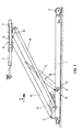
- FIG. 1 shows a schematic side view of a lifting platform according to the invention and
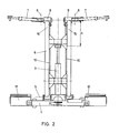
- FIG. 2 shows a partial view in the direction of arrow II of FIG. 1.
- a hydraulic cylinder-piston unit 3 is pivotally supported on the base frame 1, the pivot axis 4 of which is lower than the pivot axis 5 of the lifting arm 6 for lifting a motor vehicle.
- support arms 7 are attached, which act pivotably on the free end of the lifting arm 6 about a pivot axis 8 which is essentially normal to the floor level.
- the bearing part 9, on which the support arms 7 pivotally engage, is held substantially parallel to the plane of the base frame even during the lifting process and in any position, for which purpose a parallelogram link 10 is provided, which acts on the bearing part 9 via an angle arm 11.
- the drive motor for the hydraulics is designated by 12 in FIG.
- the lifting platform is not yet at the nominal height, since the angle between the axis of the hydraulic cylinder-piston unit 3 and the plane given by the base frame is still less than 75 °.
- the pressure in the hydraulic cylinder-piston unit 3 is larger than in a position in which the axis of the cylinder-piston unit 3 is at an angle of 75 ° to 105 ° to the level of the base frame and it can therefore be used to raise or raise the lift the pressure of the medium in hydraulic cylinder-piston unit are monitored by means of a schematically illustrated pressure sensor 13.
- the further pressure medium supply is switched off. Since the pressure at the start of the lifting process is significantly greater than in the end position, it is in any case additionally desirable to provide an angular position sensor which engages on the pivot axis 4 and is indicated schematically by 14, which ensures that the correspondingly higher pressure at the start of the lifting process Is made available and a pressure-dependent shutdown takes place only after reaching a predetermined minimum pivot position.
- the hydraulic cylinder-piston unit 3 acts at a distance a from the free end of the lifting arm 6 on the lifting arm 6, which corresponds to approximately one third of the length of the lifting arm in the illustration in FIG. In this way it is possible to design the free end of the lifting arm 6 without loss of stability as an essentially U-shaped carrier, the free legs of which are denoted by 15 and 16.
- the bearing part 9 for the support arms 7 is in turn connected to each of these free legs 15 and 16, and each of these two bearing parts 9 is guided parallel to the plane of the base frame 1 via a separate parallelogram rod 10. A corresponding free space thus remains between the two free legs 15 and 16 of the U-shaped carrier the expansion of cardan shafts, exhaust systems or the like. facilitated.
- ramps and running surfaces 17 connected to the side of the base frame are indicated schematically.
- the lifting arm 6 can be lowered by pivoting about the pivot axis 5 into a position between these lateral ramp parts or tread parts 17.
Landscapes
- Life Sciences & Earth Sciences (AREA)
- Engineering & Computer Science (AREA)
- Geology (AREA)
- Mechanical Engineering (AREA)
- Structural Engineering (AREA)
- Handcart (AREA)
- Forklifts And Lifting Vehicles (AREA)
- Actuator (AREA)
- Vehicle Step Arrangements And Article Storage (AREA)
- Medicines That Contain Protein Lipid Enzymes And Other Medicines (AREA)
Claims (5)
- Plate-forme élévatrice mobile destinée à soulever des véhicules automobiles, comprenant un bras élévateur pivotant qui est articulé sur un châssis de base mobile (1) pour pouvoir pivoter et pour pouvoir être abaissé à une position contenue entre des éléments latéraux du châssis de base (1), le bras élévateur (6) portant à son extrémité libre des bras porteurs (7) qui sont guidés à l'aide d'une tringlerie en forme de parallélogramme (10) de façon à rester parallèles au plan du sol, et le bras élévateur (6) peut pivoter sous l'action d'un groupe hydraulique cylindre-piston (3) qui applique sa force à une distance de l'axe de pivotement du bras élévateur (6), celui-ci étant essentiellement constitué, entre le point d'application de la force du groupe cylindre-piston (3) et le point d'articulation des bras supports (7), par une poutre en U qui s'ouvre vers l'extrémité libre du bras, caractérisée en ce que le groupe hydraulique cylindre-piston (3) est articulé sur le châssis de base (1) à distance de l'axe de pivotement (5) du bras élévateur (6) et applique sa force au bras élévateur entre l'axe de pivotement (5) et l'extrémité libre du bras élévateur (3), à une distance de l'extrémité libre du bras élévateur (6) qui correspond à au moins 15% de la longueur du bras élévateur (6), de sorte que, à la hauteur de service maximale des bras porteurs (7), on obtient un angle de pivotement de l'axe du groupe cylindre-piston (3) par rapport au plan du sol qui est compris entre 75° et 105°, et de préférence égale à environ 90°, et en ce que les parties latérales du châssis de base (1) forment une rampe d'entrée.
- Plate-forme élévatrice selon la revendication 1, caractérisée en ce que les bras porteurs (7) sont articulés aux extrémités libres (15,16) de la poutre en U ouverte, d'une façon conne en soi, pour pouvoir tourner autour d'un axe (8) sensiblement perpendiculaire au plan du sol et partent de ce point d'articulation avec une inclinaison vers le haut d'un angle d'au moins 5°.
- Plate-forme élévatrice selon l'une des revendications 1 ou 2, caractérisée en ce qu'il est prévu une tringlerie en forme de parallélogramme (10) pour les bras porteurs (7) de chacune des branches (15,16) du U du bras élévateur (6).
- Plate-forme élévatrice selon l'une des revendications 1, 2 ou 3, caractérisée en ce que le groupe cylindre-piston (3) est muni d'un capteur (4) de position angulaire et/ou d'un capteur de pression (13) pour le fluide hydraulique.
- Procédé pour soulever un véhicule automobile à l'aide d'une plate-forme élévatrice selon l'une des revendications 1 à 4, dans lequel l'acheminement du fluide hydraulique est commandé en fonction de la pression régnant dans le groupe cylindre-piston (3), et est arrêté lorsque cette pression tombe à une valeur minimum prédéterminée.
Applications Claiming Priority (2)
| Application Number | Priority Date | Filing Date | Title |
|---|---|---|---|
| AT905/88 | 1988-04-07 | ||
| AT90588 | 1988-04-07 |
Publications (2)
| Publication Number | Publication Date |
|---|---|
| EP0336927A1 EP0336927A1 (fr) | 1989-10-11 |
| EP0336927B1 true EP0336927B1 (fr) | 1992-11-25 |
Family
ID=3502544
Family Applications (1)
| Application Number | Title | Priority Date | Filing Date |
|---|---|---|---|
| EP89890095A Expired - Lifetime EP0336927B1 (fr) | 1988-04-07 | 1989-04-06 | Pont de voiture mobile |
Country Status (5)
| Country | Link |
|---|---|
| US (1) | US5025892A (fr) |
| EP (1) | EP0336927B1 (fr) |
| AT (1) | ATE82737T1 (fr) |
| CA (1) | CA1318312C (fr) |
| DE (1) | DE58902797D1 (fr) |
Cited By (1)
| Publication number | Priority date | Publication date | Assignee | Title |
|---|---|---|---|---|
| CN110546103A (zh) * | 2017-04-13 | 2019-12-06 | 格哈特·芬克贝纳 | 升降平台 |
Families Citing this family (16)
| Publication number | Priority date | Publication date | Assignee | Title |
|---|---|---|---|---|
| US5156238A (en) * | 1991-11-18 | 1992-10-20 | Delaware Capital Formation, Inc. | Portable surface lift for a vehicle |
| US5340082A (en) * | 1992-03-30 | 1994-08-23 | Delaware Capital Formation, Inc. | Portable surface lift for a vehicle |
| JPH08506560A (ja) * | 1993-08-10 | 1996-07-16 | アッカーマン インター リミテッド | 水平持上げ装置 |
| US6241049B1 (en) * | 1998-05-26 | 2001-06-05 | William C. Gooch | Apparatus for storing vehicles with multiple support platforms, collapsible supports between platforms, and a torque-reaction arm lift system |
| DE19839835A1 (de) * | 1998-09-02 | 2000-03-16 | Gerhard Finkbeiner | Hebevorrichtung |
| RU2184074C1 (ru) * | 2000-12-20 | 2002-06-27 | Общество с ограниченной ответственностью "Гароми плюс" | Подъемник для автомобилей |
| US6644615B1 (en) | 2002-07-03 | 2003-11-11 | Larin Corporation | Stabilized jack stand |
| US7360983B2 (en) * | 2003-04-04 | 2008-04-22 | Pate Buck A | Portable elevated vehicle display |
| US7509187B2 (en) * | 2005-02-28 | 2009-03-24 | The Braun Corporation | Wheelchair lift with a rotary sensor used to determine lift position |
| US20060245873A1 (en) * | 2005-03-31 | 2006-11-02 | Black Jim D | Snowmobile lifting device |
| CN103507872B (zh) * | 2013-09-18 | 2016-05-18 | 立马车业集团有限公司 | 车架装配输送线 |
| DE102016002924A1 (de) * | 2016-03-04 | 2017-09-07 | Ventzki Handling Systems Gmbh & Co. Kg | Hebevorrichtung |
| US10377611B2 (en) * | 2016-10-28 | 2019-08-13 | Advance Lifts, Inc. | Scissors lift with height sensor system |
| CN110361209B (zh) * | 2019-06-10 | 2021-11-19 | 乐歌人体工学科技股份有限公司 | 升降平台平衡调节方法 |
| DE102020205451B4 (de) | 2020-04-29 | 2025-11-27 | Volkswagen Aktiengesellschaft | Mobile Hebevorrichtung |
| DE102024110558A1 (de) | 2024-04-15 | 2025-10-16 | Ewo Fluid Power Gmbh | Hydraulischer Wagenheber |
Family Cites Families (22)
| Publication number | Priority date | Publication date | Assignee | Title |
|---|---|---|---|---|
| US2629583A (en) * | 1945-10-18 | 1953-02-24 | Auto Specialties Mfg Co | Hydraulic jack |
| US2576908A (en) * | 1947-09-20 | 1951-11-27 | Walco Inc | Hoisting apparatus |
| DE1120096B (de) * | 1959-03-17 | 1961-12-21 | Ind Technik M B H Ges | Schwenkhebebuehne |
| US3065573A (en) * | 1959-08-13 | 1962-11-27 | Goldberg Samuel | Building construction |
| DE1124654B (de) * | 1960-09-09 | 1962-03-01 | Ind Technik M B H Ges | Schwenkhebebuehne |
| CH393679A (de) * | 1962-04-11 | 1965-06-15 | Focke Wulf Gmbh | Ortsveränderliche Hebebühne zum Anheben und Schrägstellen eines Kraftwagens |
| US3276548A (en) * | 1963-08-28 | 1966-10-04 | Tecalemit Engineering | Safety devices for hoists |
| FR1413813A (fr) * | 1964-11-18 | 1965-10-08 | Trepel K G Maschinenfabrik | Cric roulant |
| DE1965142C3 (de) * | 1969-12-27 | 1979-09-27 | Kaspar 8940 Memmingen Klaus | Einrichtung zum Parken zweier Fahrzeuge übereinander |
| DE2117451A1 (de) * | 1970-04-08 | 1971-10-28 | Tranchero, Jacques, Piasco, Cuneo (Italien) | Fahrbare^ Wagenheber, insbesondere für Kraftfahrzeuge, mit automatischer Sicherheitsvorrichtung |
| US3814414A (en) * | 1972-07-24 | 1974-06-04 | H Chapa | Medical examination table |
| US3783976A (en) * | 1972-07-26 | 1974-01-08 | J Kerr | Safety device for hydraulically operated lift |
| US3806109A (en) * | 1972-08-14 | 1974-04-23 | Tri W G Inc | Tiltable treatment table |
| GB2053152A (en) * | 1979-07-11 | 1981-02-04 | Mecanica Y Oleohidraulica Auxi | Garage lifts |
| DE3000492A1 (de) * | 1980-01-08 | 1981-07-09 | Hillesheimer, Walter, Dipl.-Ing. Dr., 6078 Neu-Isenburg | Hydraulisch betriebene hebebuehne o.dgl. |
| US4323141A (en) * | 1980-03-11 | 1982-04-06 | Fmc Corporation | Rail-mounted vehicle jack |
| US4548387A (en) * | 1984-04-27 | 1985-10-22 | Euro California, Inc. | Mobile hoist |
| DE3421159A1 (de) * | 1984-06-07 | 1985-12-12 | Shu Chern Chia-Yi City Liang | Auf raedern fahrbarer wagenheber |
| US4724930A (en) * | 1985-03-25 | 1988-02-16 | 554072 Ontario Inc. | Hydraulic lift |
| DE3605650C2 (de) * | 1986-02-21 | 1994-10-20 | Gerhard Dipl Ing Finkbeiner | Hydraulische Hebebühne |
| ZA861660B (en) * | 1986-03-14 | 1987-05-13 | Shinn Fu Corporation | High-speed jack assisted by rear wheels or by both the front and the rear wheels |
| GB8610634D0 (en) * | 1986-04-30 | 1986-06-04 | Kertesz S J F | Garage hoist |
-
1989
- 1989-02-24 CA CA000591993A patent/CA1318312C/fr not_active Expired - Fee Related
- 1989-04-04 US US07/332,975 patent/US5025892A/en not_active Expired - Fee Related
- 1989-04-06 DE DE8989890095T patent/DE58902797D1/de not_active Expired - Lifetime
- 1989-04-06 EP EP89890095A patent/EP0336927B1/fr not_active Expired - Lifetime
- 1989-04-06 AT AT89890095T patent/ATE82737T1/de not_active IP Right Cessation
Cited By (2)
| Publication number | Priority date | Publication date | Assignee | Title |
|---|---|---|---|---|
| CN110546103A (zh) * | 2017-04-13 | 2019-12-06 | 格哈特·芬克贝纳 | 升降平台 |
| CN110546103B (zh) * | 2017-04-13 | 2021-04-20 | 格哈特·芬克贝纳 | 升降平台 |
Also Published As
| Publication number | Publication date |
|---|---|
| ATE82737T1 (de) | 1992-12-15 |
| DE58902797D1 (de) | 1993-01-07 |
| US5025892A (en) | 1991-06-25 |
| CA1318312C (fr) | 1993-05-25 |
| EP0336927A1 (fr) | 1989-10-11 |
Similar Documents
| Publication | Publication Date | Title |
|---|---|---|
| EP0336927B1 (fr) | Pont de voiture mobile | |
| EP2243742B1 (fr) | Plate-forme de levage à ciseaux | |
| DE102005032027A1 (de) | Hubvorrichtung | |
| EP0983897A2 (fr) | Dispositif de levage | |
| DE2124237A1 (de) | Fahrzeug zur Handhabung von Lasten | |
| EP3609833B1 (fr) | Élévateur pour lever des véhicules | |
| DE2116842A1 (de) | Fahrbarer, zum Aufbau auf Kraftfahrzeuge bestimmter Kran mit drei hydraulisch gesteuerten Hebestufen | |
| DE69016336T2 (de) | Faltbares Verdeck für eine Ladefläche. | |
| EP0045398A1 (fr) | Dispositif combiné pour échanger et basculer des superstructures de véhicule utilitaire | |
| DE10361322B4 (de) | Zur Wartung von Fahrzeugen verwendete Hebebühne | |
| EP0697367A1 (fr) | Plate-forme de levage à ciseaux | |
| DE1912970A1 (de) | Hubfahrzeug | |
| DE202017005427U1 (de) | Hebevorrichtung | |
| DE3439292A1 (de) | Hydraulisch betaetigte hubvorrichtung, insbesondere hebebuehne fuer kraftfahrzeuge | |
| DE2843587A1 (de) | Hebebuehne mit ausleger | |
| DE3405502A1 (de) | Fahrzeug mit geraet zum aufnehmen, kippen und/oder absetzen von behaeltern oder dgl. | |
| DE2436672A1 (de) | Zwei-saeulen-hebebuehne, insbesondere fuer kraftfahrzeuge | |
| DE2426647A1 (de) | Reichweitenverlaengerungsvorrichtung fuer senkrechthubfahrzeuge | |
| DE3431561A1 (de) | Nutzfahrzeug mit kombinierter verladeeinrichtung | |
| EP2946971A2 (fr) | Système de chargement pour un véhicule | |
| DE60209872T2 (de) | Verbesserungen an und betreffend Gabelstablern | |
| DE10328925B3 (de) | Dreibockheber zum Anheben von Hubschraubern | |
| DE1580021C (de) | Lastfahrzeug mit auswechselbarem Aufbau | |
| DE1755980C3 (de) | Lastkraftfahrzeug zum Transport von bodenlosen und zumindest einseitig offenen Bauwerkszellen | |
| DE2405422A1 (de) | Transportfahrzeug zum aufnehmen und absetzen von wechselaufbauten |
Legal Events
| Date | Code | Title | Description |
|---|---|---|---|
| PUAI | Public reference made under article 153(3) epc to a published international application that has entered the european phase |
Free format text: ORIGINAL CODE: 0009012 |
|
| AK | Designated contracting states |
Kind code of ref document: A1 Designated state(s): AT BE CH DE FR GB IT LI NL |
|
| 17P | Request for examination filed |
Effective date: 19900403 |
|
| 17Q | First examination report despatched |
Effective date: 19910318 |
|
| RAP1 | Party data changed (applicant data changed or rights of an application transferred) |
Owner name: STELZL HYDRAULIK-GESELLSCHAFT M.B.H. |
|
| GRAA | (expected) grant |
Free format text: ORIGINAL CODE: 0009210 |
|
| AK | Designated contracting states |
Kind code of ref document: B1 Designated state(s): AT BE CH DE FR GB IT LI NL |
|
| REF | Corresponds to: |
Ref document number: 82737 Country of ref document: AT Date of ref document: 19921215 Kind code of ref document: T |
|
| REF | Corresponds to: |
Ref document number: 58902797 Country of ref document: DE Date of ref document: 19930107 |
|
| ITF | It: translation for a ep patent filed | ||
| ET | Fr: translation filed | ||
| GBT | Gb: translation of ep patent filed (gb section 77(6)(a)/1977) |
Effective date: 19930122 |
|
| PLBE | No opposition filed within time limit |
Free format text: ORIGINAL CODE: 0009261 |
|
| STAA | Information on the status of an ep patent application or granted ep patent |
Free format text: STATUS: NO OPPOSITION FILED WITHIN TIME LIMIT |
|
| 26N | No opposition filed | ||
| PGFP | Annual fee paid to national office [announced via postgrant information from national office to epo] |
Ref country code: GB Payment date: 19940331 Year of fee payment: 6 |
|
| PG25 | Lapsed in a contracting state [announced via postgrant information from national office to epo] |
Ref country code: GB Effective date: 19950406 |
|
| PGFP | Annual fee paid to national office [announced via postgrant information from national office to epo] |
Ref country code: NL Payment date: 19951031 Year of fee payment: 7 |
|
| GBPC | Gb: european patent ceased through non-payment of renewal fee |
Effective date: 19950406 |
|
| PGFP | Annual fee paid to national office [announced via postgrant information from national office to epo] |
Ref country code: BE Payment date: 19960510 Year of fee payment: 8 |
|
| PG25 | Lapsed in a contracting state [announced via postgrant information from national office to epo] |
Ref country code: NL Effective date: 19961101 |
|
| NLV4 | Nl: lapsed or anulled due to non-payment of the annual fee |
Effective date: 19961101 |
|
| PGFP | Annual fee paid to national office [announced via postgrant information from national office to epo] |
Ref country code: CH Payment date: 19970414 Year of fee payment: 9 |
|
| PG25 | Lapsed in a contracting state [announced via postgrant information from national office to epo] |
Ref country code: BE Effective date: 19970430 |
|
| PGFP | Annual fee paid to national office [announced via postgrant information from national office to epo] |
Ref country code: FR Payment date: 19970430 Year of fee payment: 9 |
|
| BERE | Be: lapsed |
Owner name: STELZL HYDRAULIK G.M.B.H. Effective date: 19970430 |
|
| PG25 | Lapsed in a contracting state [announced via postgrant information from national office to epo] |
Ref country code: CH Free format text: LAPSE BECAUSE OF NON-PAYMENT OF DUE FEES Effective date: 19980430 Ref country code: FR Free format text: THE PATENT HAS BEEN ANNULLED BY A DECISION OF A NATIONAL AUTHORITY Effective date: 19980430 Ref country code: LI Free format text: LAPSE BECAUSE OF NON-PAYMENT OF DUE FEES Effective date: 19980430 |
|
| REG | Reference to a national code |
Ref country code: CH Ref legal event code: PL |
|
| REG | Reference to a national code |
Ref country code: FR Ref legal event code: ST |
|
| PG25 | Lapsed in a contracting state [announced via postgrant information from national office to epo] |
Ref country code: IT Free format text: LAPSE BECAUSE OF NON-PAYMENT OF DUE FEES;WARNING: LAPSES OF ITALIAN PATENTS WITH EFFECTIVE DATE BEFORE 2007 MAY HAVE OCCURRED AT ANY TIME BEFORE 2007. THE CORRECT EFFECTIVE DATE MAY BE DIFFERENT FROM THE ONE RECORDED. Effective date: 20050406 |
|
| PGFP | Annual fee paid to national office [announced via postgrant information from national office to epo] |
Ref country code: DE Payment date: 20080425 Year of fee payment: 20 |
|
| PGFP | Annual fee paid to national office [announced via postgrant information from national office to epo] |
Ref country code: AT Payment date: 20080414 Year of fee payment: 20 |