EP0337070A2 - Kraftfahrzeug mit einem Verkleidungsteil - Google Patents
Kraftfahrzeug mit einem Verkleidungsteil Download PDFInfo
- Publication number
- EP0337070A2 EP0337070A2 EP89102395A EP89102395A EP0337070A2 EP 0337070 A2 EP0337070 A2 EP 0337070A2 EP 89102395 A EP89102395 A EP 89102395A EP 89102395 A EP89102395 A EP 89102395A EP 0337070 A2 EP0337070 A2 EP 0337070A2
- Authority
- EP
- European Patent Office
- Prior art keywords
- snap
- motor vehicle
- vehicle according
- recess
- trim part
- Prior art date
- Legal status (The legal status is an assumption and is not a legal conclusion. Google has not performed a legal analysis and makes no representation as to the accuracy of the status listed.)
- Granted
Links
Images

Classifications
-
- F—MECHANICAL ENGINEERING; LIGHTING; HEATING; WEAPONS; BLASTING
- F16—ENGINEERING ELEMENTS AND UNITS; GENERAL MEASURES FOR PRODUCING AND MAINTAINING EFFECTIVE FUNCTIONING OF MACHINES OR INSTALLATIONS; THERMAL INSULATION IN GENERAL
- F16B—DEVICES FOR FASTENING OR SECURING CONSTRUCTIONAL ELEMENTS OR MACHINE PARTS TOGETHER, e.g. NAILS, BOLTS, CIRCLIPS, CLAMPS, CLIPS OR WEDGES; JOINTS OR JOINTING
- F16B21/00—Means for preventing relative axial movement of a pin, spigot, shaft or the like and a member surrounding it; Stud-and-socket releasable fastenings
- F16B21/06—Releasable fastening devices with snap-action
- F16B21/08—Releasable fastening devices with snap-action in which the stud, pin, or spigot has a resilient part
- F16B21/088—Releasable fastening devices with snap-action in which the stud, pin, or spigot has a resilient part the stud, pin or spigot being integrally formed with the component to be fastened, e.g. forming part of the sheet, plate or strip
-
- B—PERFORMING OPERATIONS; TRANSPORTING
- B60—VEHICLES IN GENERAL
- B60K—ARRANGEMENT OR MOUNTING OF PROPULSION UNITS OR OF TRANSMISSIONS IN VEHICLES; ARRANGEMENT OR MOUNTING OF PLURAL DIVERSE PRIME-MOVERS IN VEHICLES; AUXILIARY DRIVES FOR VEHICLES; INSTRUMENTATION OR DASHBOARDS FOR VEHICLES; ARRANGEMENTS IN CONNECTION WITH COOLING, AIR INTAKE, GAS EXHAUST OR FUEL SUPPLY OF PROPULSION UNITS IN VEHICLES
- B60K11/00—Arrangement in connection with cooling of propulsion units
- B60K11/08—Air inlets for cooling; Shutters or blinds therefor
-
- B—PERFORMING OPERATIONS; TRANSPORTING
- B60—VEHICLES IN GENERAL
- B60R—VEHICLES, VEHICLE FITTINGS, OR VEHICLE PARTS, NOT OTHERWISE PROVIDED FOR
- B60R13/00—Elements for body-finishing, identifying, or decorating; Arrangements or adaptations for advertising purposes
Definitions
- the invention relates to a motor vehicle with a trim part according to the preamble of patent claim 1.
- the trim part is held in position by means of an additional fastening element on the body.
- the fastening element is fixed on the one hand via a clip connection on the body part and on the other hand has snap hooks which engage in recesses in the trim part.
- the object of the invention is to provide an inexpensive attachment of a trim part to an adjacent body part with easy assembly and simple construction.
- a secure rattle-free connection between the trim part and the body part is to be created for a long time.
- the main advantages achieved with the invention can be seen in the fact that the direct attachment of the trim part to the body part makes assembly much easier and the elimination of the additional fastening element reduces the costs.
- the resilient, resilient web that delimits the recess ensures easy assembly and a secure, rattle-free fit of the trim part.
- the trim part 1 shows a trim part 1 made of plastic for a motor vehicle, which is held in position by a plurality of snap connections 2 on the adjacent body part 3.
- the trim part 1 is formed by an air inlet grille 4 arranged on the bow side.
- the structural part 3 is shown in FIG. 1 as a bow trim 5, which is made of an elastic material such as glass fiber reinforced plastic or the like.
- Each snap connection 2 comprises a snap hook 6 molded onto the structural part 3, which engages in an associated recess 7 of the fitted covering part 1.
- the snap hooks 6 formed in one piece with the mounting part 3 are aligned approximately horizontally and are guided away from the mounting part 3 against the direction of travel A.
- Each snap hook 6 comprises a foot section 8 and a snap head 9, the snap head 9 having a greater height than the foot section 8.
- the recess 7 on the trim part 1 has approximately a trapezoidal shape 10, the longer of the horizontally oriented sides 11 of the trapezoid running adjacent to a resilient web 12 of the trim part 1.
- the recess 7 has a substantially greater width than the snap head 9, so that different lengths of the trim part 1 and body part 3 can be compensated.
- the resilient web 12 extends between the recess 7 receiving the snap hook 6 and an adjacent longitudinal slot 13.
- the longitudinal slot 13 has a greater height in a central region of its transverse extent than in the laterally outer edge regions.
- the web 12 is provided above the flat outer surface 14 of the snap hook 6 and, viewed in the vertical direction, is relatively thin-walled, so that during assembly of the trim part 1 it moves from an approximately horizontal rest position B into an outwardly bent, dash-dotted installation position G, is movable. After passing the snap head 9, the web 12 returns to its rest position B.
- the recess 7 has a slightly greater height than the foot section 8 of the snap hook 6 (play seat), whereas the snap head 9 has a greater height than the recess 7.
- a sloping contact surface 15 provided on the snap head 9 facilitates the insertion of the snap hook 6 into the recesses 7.
- the snap heads 9 are only provided in the area of the fastening points for the trim part 1, whereas the foot sections 8 of the snap hooks 6 extend over the entire width of the mounting part 3 extend and form two superimposed air duct 16 on the body part 3.
- the air duct 16 have a large-meshed grid structure 21 in the area of the trim part 1.
- a plurality of snap connections 2 arranged side by side and one above the other are provided.
- the snap heads 9 protrude the trim part 1 towards the rear, a step-shaped shoulder 17 of the snap head 9 being supported on the rear side 18 of the trim part 1.
- the structural part 3 has two air duct channels 16 lying one above the other, which are delimited by the outer, horizontal foot sections 8 of the snap hooks 6 and an approximately U-shaped central web 19.
- the snap hooks 6 are arranged invisibly from the outside of the vehicle.
- the trim part 1 is placed on the body part 3 from behind. Seen in the vehicle longitudinal direction, the trim part is fixed by the snap head 9 and inclined wall sections 20 of the body part 3, the inclined wall sections 20 being on the step-shaped Paragraphs 17 opposite side of the structural part 3 are arranged. According to FIG. 2, three snap connections 2 arranged one above the other are provided on the trim part 1 at 22, 23 and 24.
Landscapes
- Engineering & Computer Science (AREA)
- Mechanical Engineering (AREA)
- General Engineering & Computer Science (AREA)
- Chemical & Material Sciences (AREA)
- Combustion & Propulsion (AREA)
- Transportation (AREA)
- Vehicle Interior And Exterior Ornaments, Soundproofing, And Insulation (AREA)
- Connection Of Plates (AREA)
- Body Structure For Vehicles (AREA)
Abstract
Description
- Die Erfindung betrifft ein Kraftfahrzeug mit einem Verkleidungsteil gemäß dem Oberbegriff des Patentanspruchs 1.
- Bei einem bekannten Kraftfahrzeug (US-PS 4 354 566) wird das Verkleidungsteil unter Vermittlung eines zusätzlichen Befestigungselementes am Aufbau in Lage gehalten. Das Befestigungselement wird einerseits über eine Clipsverbindung am Aufbauteil fixiert und weist andererseits Schnapphaken auf, die in Ausnehmungen des Verkleidungsteiles eingreifen.
- Dieser Anordnung haftet der Nachteil an, daß wegen der separaten Befestigungselemente die Montage und Befestigung des Verkleidungsteiles kostenaufwendig ist. Da die Ausnehmungen für die Schnapphaken eine wesentlich größere Höhe aufweisen als die Fußabschnitte der Schnapphaken, kann es vorkommen, daß bedingt durch die Alterung des Kunststoffes Klappergeräusche zwischen Befestigungselement und Verkleidungsteil auftreten.
- Aufgabe der Erfindung ist es, bei leichter Montage und einfachem Aufbau eine kostengünstige Befestigung eines Verkleidungsteiles an einem angrenzenden Aufbauteil zu schaffen. Darüber hinaus soll langzeitig eine sichere klapperfreie Verbindung zwischen Verkleidungsteil und Aufbauteil geschaffen werden.
- Erfindungsgemäß wird diese Aufgabe durch die kennzeichnenden Merkmale des Anspruchs 1 gelöst. Weitere, die Erfindung in vorteilhafter Weise ausgestaltende Merkmale enthalten die Unteransprüche.
- Die mit der Erfindung hauptsächlich erzielten Vorteile sind darin zu sehen, daß durch die unmittelbare Befestigung des Verkleidungsteiles am Aufbauteil die Montage wesentlich erleichtert und durch den Entfall des zusätzlichen Befestigungselementes die Kosten reduziert werden. Durch den die Ausnehmung begrenzenden, federnd nachgiebigen Steg wird eine leichte Montage und ein sicherer, klapperfreier Sitz des Verkleidungsteiles gewährleistet.
- Ein Ausführungsbeispiel der Erfindung ist in der Zeichnung dargestellt und wird im folgenden näher erläutert. Es zeigt
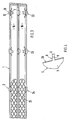
- Fig. 1 einen Vertikalschnitt durch ein Verkleidungsteil und ein Aufbauteil eines Kraftfahrzeuges,
- Fig. 2 eine Teilansicht in Pfeilrichtung R der Fig. 1 in größerem Maßstab,
- Fig. 3 eine Teilansicht in Pfeilrichtung S der Fig. 1 auf das Verkleidungsteil in kleinerem Maßstab,
- Fig. 4 eine Teilansicht in Pfeilrichtung T der Fig. 1.
- In Fig. 1 ist ein aus Kunststoff hergestelltes Verkleidungsteil 1 für ein Kraftfahrzeug dargestellt, das über mehrere Schnappverbindungen 2 am angrenzenden Aufbauteil3 in Lage gehalten ist. Das Verkleidungsteil 1 wird im Ausführungsbeispiel durch ein bugseitig angeordnetes Lufteinlaßgitter 4 gebildet. Das Aufbauteil 3 ist gemäß Fig. 1 als eine Bugverkleidung 5 dargestellt, die aus einem elastischen Werkstoff wie glasfaserverstärktem Kunststoff oder dergleichen, gefertigt ist.
- Eine einfache kostengünstige Befestigung des Verkleidungsteiles 1 wird dadurch erzielt, daß letzteres ohne zusätzliche Befestigungselemente (Klammern, Schrauben oder dergleichen) am Aufbauteil 3 befestigt ist. Jede Schnappverbindung 2 umfaßt einen am Aufbauteil 3 angespritzten Schnapphaken 6, der in eine zugeordnete Ausnehmung 7 des aufgesetzten Verkleidungsteiles 1 eingreift. Die einstückig mit dem Aufbauteil 3 ausgebildeten Schnapphaken 6 sind etwa horizontal ausgerichet und vom Aufbauteil 3 entgegen der Fahrtrichtung A weggeführt. Jeder Schnapphaken 6 umfaßt einen Fußabschnitt 8 und einen Schnappkopf 9, wobei der Schnappkopf 9 eine größere Höhe aufweist als der Fußabschnitt 8.
- Die Ausnehmung 7 am Verkleidungsteil 1 weist annähernd eine Trapezform 10 auf, wobei die längere der horizontal ausgerichteten Seiten 11 des Trapezes benachbart einem federnd nachgiebigen Steg 12 des Verkleidungsteiles 1 verläuft.
- Die Ausnehmung 7 weist eine wesentlich größere Breite auf als der Schnappkopf 9, so daß unterschiedliche Längenausdehnungen von Verkleidungsteil 1 und Aufbauteil 3 kompensiert werden können. Der federnd nachgiebige Steg 12 erstreckt sich zwischen der den Schnapphaken 6 aufnehmenden Ausnehmung 7 und einem benachbart dazu angeordneten Längsschlitz 13. Der Längsschlitz 13 weist in einem mittleren Bereich seiner Quererstreckung eine größere Höhe auf als in den seitlich außenliegenden Randbereichen. Der Steg 12 ist oberhalb der eben ausgebildeten Außenfläche 14 des Schnapphakens 6 vorgesehen und in Höhenrichtung gesehen, relativ dünnwandig ausgebildet, so daß er bei der Montage des Verkleidungsteiles 1 von einer etwa horizontal verlaufenden Ruhestellung B in eine nach außen gebogene, strichpunktiert dargestellte Einbaulage G, bewegbar ist. Nach dem Hindurchführen des Schnappkopfes 9 kehrt der Steg 12 wieder in seine Ruhestellung B zurück. Die Ausnehmung 7 weist eine geringfügig größere Höhe auf als der Fußabschnitt 8 des Schnapphakens 6 (Spielsitz), wogegen der Schnappkopf 9 eine größere Höhe besitzt als die Ausnehmung 7.
- Eine am Schnappkopf 9 vorgesehene, schrägverlaufende Anlauffläche 15 erleichtert das Einführen des Schnapphakens 6 in die Ausnehmungen 7. Die Schnappköpfe 9 sind lediglich im Bereich der Befestigungsstellen für das Verkleidungsteil 1 vorgesehen, wogegen sich die Fußabschnitte 8 der Schnapphaken 6 über die gesamte Breite des Aufbauteiles 3 erstrecken und zwei übereinanderliegende Luftführungskanäle 16 am Aufbauteil 3 bilden. Die Luftführungskanäle 16 weisen im Bereich des Verkleidungsteiles 1 eine großmaschige Gitterstruktur 21 auf.
- Für das relativ großflächige Verkleidungsteil 1 sind mehrere nebeneinander - und übereinanderliegend angeordente Schnappverbindungen 2 vorgesehen.
- Gemäß Fig. 1 überragen die Schnappköpfe 9 das Verkleidungsteil 1 nach hinten hin, wobei sich ein stufenförmiger Absatz 17 des Schnappkopfes 9 an der hintenliegenden Seite 18 des Verkleidungsteiles 1 abstützt. Das Aufbauteil 3 weist zwei übereinanderliegende Luftführungskanäle 16 auf, die von den außenliegenden, horizontalen Fußabschnitten 8 der Schnapphaken 6 und einem etwa U-förmigen Mittelsteg 19 begrenzt werden. Die Schnapphaken 6 sind von der Fahrzeugaußenseite her unsichtbar angeordnet.
- Das Verkleidungsteil 1 wird von hinten auf das Aufbauteil 3 aufgesetzt. In Fahrzeuglängsrichtung gesehen, wird das Verkleidungsteil durch den Schnappkopf 9 und schrägverlaufende Wandabschnitte 20 des Aufbauteiles 3 fixiert, wobei die schrägverlaufenden Wandabschnitte 20 auf der den stufenförmigen Absätzen 17 gegenüberliegenden Seite des Aufbauteiles 3 angeordnet sind. Gemäß Fig. 2 sind bei 22, 23 und 24 am Verkleidungsteil 1 jeweils drei übereinanderliegend angeordnete Schnappverbindungen 2 vorgesehen.
Claims (10)
Applications Claiming Priority (2)
| Application Number | Priority Date | Filing Date | Title |
|---|---|---|---|
| DE3812347A DE3812347A1 (de) | 1988-04-14 | 1988-04-14 | Kraftfahrzeug mit einem verkleidungsteil |
| DE3812347 | 1988-04-14 |
Publications (3)
| Publication Number | Publication Date |
|---|---|
| EP0337070A2 true EP0337070A2 (de) | 1989-10-18 |
| EP0337070A3 EP0337070A3 (de) | 1991-04-03 |
| EP0337070B1 EP0337070B1 (de) | 1993-11-10 |
Family
ID=6351925
Family Applications (1)
| Application Number | Title | Priority Date | Filing Date |
|---|---|---|---|
| EP89102395A Expired - Lifetime EP0337070B1 (de) | 1988-04-14 | 1989-02-11 | Kraftfahrzeug mit einem Verkleidungsteil |
Country Status (4)
| Country | Link |
|---|---|
| US (1) | US4966245A (de) |
| EP (1) | EP0337070B1 (de) |
| DE (2) | DE3812347A1 (de) |
| ES (1) | ES2045212T3 (de) |
Cited By (1)
| Publication number | Priority date | Publication date | Assignee | Title |
|---|---|---|---|---|
| EP1010587A1 (de) * | 1998-12-18 | 2000-06-21 | Lab Radio, Ctra. | Kühlergrill für Fahrzeug |
Families Citing this family (14)
| Publication number | Priority date | Publication date | Assignee | Title |
|---|---|---|---|---|
| US5352010A (en) * | 1992-03-10 | 1994-10-04 | Brodie James L | Post attached structures for window assemblies |
| US5226695A (en) * | 1992-06-19 | 1993-07-13 | General Motors Corporation | Fascia to fender attachment |
| DE19507986C2 (de) * | 1995-03-07 | 1997-11-20 | Audi Ag | Festlegung eines Kunststoff-Formteiles an einem Absatz einer Fahrzeugkarosserie |
| IT238848Y1 (it) * | 1995-05-23 | 2000-11-15 | Plastal Zcp Spa | Calandra per autoveicoli |
| FR2796020B1 (fr) | 1999-07-06 | 2001-09-14 | Plastic Omnium Cie | Bandeau de pare-chocs et pare-chocs muni d'un tel bandeau |
| JP4725365B2 (ja) * | 2006-03-01 | 2011-07-13 | 日産自動車株式会社 | 係合固定構造および係合固定方法 |
| DE102006032597A1 (de) * | 2006-07-14 | 2008-01-17 | Dr.Ing.H.C. F. Porsche Ag | Befestigungsvorrichtung für ein Anbauteil eines Kraftfahrzeugs |
| US7445259B1 (en) | 2007-06-08 | 2008-11-04 | Ford Global Technologies, Llc | Fascia anti-rattle springs |
| DE102008020082A1 (de) * | 2008-04-22 | 2009-10-29 | Dr. Ing. H.C. F. Porsche Aktiengesellschaft | Luftleitbauteil und Karosserievorbau eines Kraftfahrzeuges |
| FR2967375B1 (fr) * | 2010-11-17 | 2012-12-14 | Renault Sa | Dispositif de refroidissement a guide d'air pour radiateur de moteur automobile |
| DE102012216138A1 (de) * | 2012-09-12 | 2014-05-28 | Bayerische Motoren Werke Aktiengesellschaft | Lufteinlassvorrichtung für ein Fahrzeug |
| DE102016214454B4 (de) * | 2016-08-04 | 2024-06-20 | Dr. Ing. H.C. F. Porsche Aktiengesellschaft | Karosseriestruktur eines Kraftfahrzeugs und Kraftfahrzeug |
| US10116610B2 (en) | 2016-08-31 | 2018-10-30 | Keystone Automotive Operations, Inc. | Automotive wheel overlay attachment system |
| DE102023132033A1 (de) * | 2023-11-17 | 2025-05-22 | Dr. Ing. H.C. F. Porsche Aktiengesellschaft | Karosseriesichtelement einer Kraftfahrzeugkarosserie mit einem Abdeckelement |
Family Cites Families (10)
| Publication number | Priority date | Publication date | Assignee | Title |
|---|---|---|---|---|
| DE7009036U (de) * | 1970-03-12 | 1971-09-02 | Haubitz & Co Dr | Schutzgitter fuer kanalartige luftfuehrungen, insbesondere bei luftgekuehlten motoren von kraftfahrzeugen. |
| AU6196473A (en) * | 1972-11-11 | 1975-05-01 | Lucas Electrical Co Ltd | Electrical assemblies |
| JPS6030571B2 (ja) * | 1979-08-23 | 1985-07-17 | 日産自動車株式会社 | 自動車用グリル取付構造 |
| JPS5631846A (en) * | 1979-08-27 | 1981-03-31 | Nissan Motor Co Ltd | Installation structure of radiator grille |
| JPS595631Y2 (ja) * | 1979-09-06 | 1984-02-20 | 株式会社 ニフコ | ラジエ−タ・グリル取付構造 |
| JPS56103236A (en) * | 1980-01-21 | 1981-08-18 | Teijin Ltd | Polyester composition |
| DE8019864U1 (de) * | 1980-07-24 | 1980-10-30 | Adam Opel Ag, 6090 Ruesselsheim | Kraftfahrzeug-frontteil aus kunststoff |
| DE8023648U1 (de) * | 1980-09-05 | 1982-02-18 | Robert Bosch Gmbh, 7000 Stuttgart | Frontteil aus kunststoff fuer kraftfahrzeuge |
| DE3125687C2 (de) * | 1981-06-30 | 1984-09-13 | Daimler-Benz Ag, 7000 Stuttgart | Stoßfänger für Kraftfahrzeuge |
| US4652036A (en) * | 1984-09-17 | 1987-03-24 | Toyoda Gosei Co., Ltd. | Air spoiler |
-
1988
- 1988-04-14 DE DE3812347A patent/DE3812347A1/de not_active Withdrawn
-
1989
- 1989-02-11 ES ES89102395T patent/ES2045212T3/es not_active Expired - Lifetime
- 1989-02-11 EP EP89102395A patent/EP0337070B1/de not_active Expired - Lifetime
- 1989-02-11 DE DE89102395T patent/DE58906130D1/de not_active Expired - Fee Related
- 1989-04-14 US US07/338,237 patent/US4966245A/en not_active Expired - Fee Related
Cited By (2)
| Publication number | Priority date | Publication date | Assignee | Title |
|---|---|---|---|---|
| EP1010587A1 (de) * | 1998-12-18 | 2000-06-21 | Lab Radio, Ctra. | Kühlergrill für Fahrzeug |
| US6206438B1 (en) | 1998-12-18 | 2001-03-27 | Lab. Radio. S.A. | Grill for vehicle front end |
Also Published As
| Publication number | Publication date |
|---|---|
| DE58906130D1 (de) | 1993-12-16 |
| DE3812347A1 (de) | 1989-10-26 |
| ES2045212T3 (es) | 1994-01-16 |
| US4966245A (en) | 1990-10-30 |
| EP0337070A3 (de) | 1991-04-03 |
| EP0337070B1 (de) | 1993-11-10 |
Similar Documents
| Publication | Publication Date | Title |
|---|---|---|
| EP0337070B1 (de) | Kraftfahrzeug mit einem Verkleidungsteil | |
| EP0850163B1 (de) | Scheibenwischblatt | |
| EP0099460B1 (de) | Scheibeneinfassung | |
| DE3523909C2 (de) | ||
| DE3043476A1 (de) | Haubenabschluss fuer ein fahrzeug | |
| WO1998001327A1 (de) | Wischblatt für scheiben von kraftfahrzeugen | |
| DE3428293A1 (de) | Windlaufoberteil-aussenplatte fuer ein kraftfahrzeug | |
| DE19522273A1 (de) | Wischblatt zum Reinigen von Scheiben an Kraftfahrzeugen | |
| DE4024035C2 (de) | Verbindung eines geräuschdämpfenden Kraftfahrzeug-Verkleidungsteiles mit dem Fahrzeugunterbau | |
| EP0185892B1 (de) | Lösbare Befestigung einer Zierleiste | |
| DE19648330B4 (de) | Kraftfahrzeugkarosserie | |
| DE4343680C1 (de) | Verkleidungsteil für eine Lufteintrittsöffnung eines Kraftfahrzeuges, insbesondere Kühlergrill für einen Personenkraftwagen | |
| DE3024312A1 (de) | Frontkonstruktion eines fahrzeuges | |
| DE69310104T2 (de) | Windleitfläche für Scheibenwischer | |
| EP0277293B1 (de) | Bodengruppe für ein Fahrzeug, insbesondere für ein Kraftfahrzeug | |
| EP0234286B1 (de) | Wischarm für Scheibenwischer | |
| DE3031623C2 (de) | Befestigung von Zierleisten o.dgl. an Wandungsteilen, insbesondere an Karosserieteilen von Kraftwagen | |
| DE4232192C2 (de) | Seitenverkleidung für Kraftfahrzeuge | |
| EP0628438B1 (de) | Einrichtung zur Befestigung eines unteren Randbereiches eines Verdeckbezuges | |
| DE10008565A1 (de) | Befestigungsclip | |
| DE69305727T2 (de) | Anordnung zur Befestigung eines Teiles auf einer Wand | |
| DE3721783A1 (de) | Anordnung zur loesbaren befestigung einer verkleidung an einem tragenden bauteil | |
| DE3033389C2 (de) | Halteklammer zum lösbaren Verbinden einer Zierleiste mit einem Tragflansch an einem Kraftfahrzeug | |
| EP1366942A2 (de) | Verdeckstoffbefestigung für ein Cabriolet | |
| DE69500448T2 (de) | Kraftfahrzeugscheibenwischer mit aerodynamischem Windabweiser |
Legal Events
| Date | Code | Title | Description |
|---|---|---|---|
| PUAI | Public reference made under article 153(3) epc to a published international application that has entered the european phase |
Free format text: ORIGINAL CODE: 0009012 |
|
| AK | Designated contracting states |
Kind code of ref document: A2 Designated state(s): DE ES FR GB IT |
|
| PUAL | Search report despatched |
Free format text: ORIGINAL CODE: 0009013 |
|
| AK | Designated contracting states |
Kind code of ref document: A3 Designated state(s): DE ES FR GB IT |
|
| 17P | Request for examination filed |
Effective date: 19910706 |
|
| 17Q | First examination report despatched |
Effective date: 19921125 |
|
| ITF | It: translation for a ep patent filed | ||
| GRAA | (expected) grant |
Free format text: ORIGINAL CODE: 0009210 |
|
| AK | Designated contracting states |
Kind code of ref document: B1 Designated state(s): DE ES FR GB IT |
|
| REF | Corresponds to: |
Ref document number: 58906130 Country of ref document: DE Date of ref document: 19931216 |
|
| ET | Fr: translation filed | ||
| GBT | Gb: translation of ep patent filed (gb section 77(6)(a)/1977) |
Effective date: 19931215 |
|
| REG | Reference to a national code |
Ref country code: ES Ref legal event code: FG2A Ref document number: 2045212 Country of ref document: ES Kind code of ref document: T3 |
|
| PGFP | Annual fee paid to national office [announced via postgrant information from national office to epo] |
Ref country code: ES Payment date: 19940216 Year of fee payment: 6 |
|
| PLBE | No opposition filed within time limit |
Free format text: ORIGINAL CODE: 0009261 |
|
| STAA | Information on the status of an ep patent application or granted ep patent |
Free format text: STATUS: NO OPPOSITION FILED WITHIN TIME LIMIT |
|
| 26N | No opposition filed | ||
| PG25 | Lapsed in a contracting state [announced via postgrant information from national office to epo] |
Ref country code: ES Free format text: LAPSE BECAUSE OF NON-PAYMENT OF DUE FEES Effective date: 19950213 |
|
| PGFP | Annual fee paid to national office [announced via postgrant information from national office to epo] |
Ref country code: FR Payment date: 19950227 Year of fee payment: 7 |
|
| PGFP | Annual fee paid to national office [announced via postgrant information from national office to epo] |
Ref country code: GB Payment date: 19960212 Year of fee payment: 8 |
|
| PG25 | Lapsed in a contracting state [announced via postgrant information from national office to epo] |
Ref country code: FR Effective date: 19961031 |
|
| REG | Reference to a national code |
Ref country code: FR Ref legal event code: ST |
|
| PG25 | Lapsed in a contracting state [announced via postgrant information from national office to epo] |
Ref country code: GB Effective date: 19970211 |
|
| GBPC | Gb: european patent ceased through non-payment of renewal fee |
Effective date: 19970211 |
|
| PGFP | Annual fee paid to national office [announced via postgrant information from national office to epo] |
Ref country code: DE Payment date: 19980218 Year of fee payment: 10 |
|
| REG | Reference to a national code |
Ref country code: ES Ref legal event code: FD2A Effective date: 19990301 |
|
| PG25 | Lapsed in a contracting state [announced via postgrant information from national office to epo] |
Ref country code: DE Free format text: LAPSE BECAUSE OF NON-PAYMENT OF DUE FEES Effective date: 19991201 |
|
| PG25 | Lapsed in a contracting state [announced via postgrant information from national office to epo] |
Ref country code: IT Free format text: LAPSE BECAUSE OF NON-PAYMENT OF DUE FEES;WARNING: LAPSES OF ITALIAN PATENTS WITH EFFECTIVE DATE BEFORE 2007 MAY HAVE OCCURRED AT ANY TIME BEFORE 2007. THE CORRECT EFFECTIVE DATE MAY BE DIFFERENT FROM THE ONE RECORDED. Effective date: 20050211 |