EP0337126A1 - Dispositif de transport pour agencer des tubes de bobines et pour emporter des bobines pour un métier à filer bilateral - Google Patents
Dispositif de transport pour agencer des tubes de bobines et pour emporter des bobines pour un métier à filer bilateral Download PDFInfo
- Publication number
- EP0337126A1 EP0337126A1 EP89104327A EP89104327A EP0337126A1 EP 0337126 A1 EP0337126 A1 EP 0337126A1 EP 89104327 A EP89104327 A EP 89104327A EP 89104327 A EP89104327 A EP 89104327A EP 0337126 A1 EP0337126 A1 EP 0337126A1
- Authority
- EP
- European Patent Office
- Prior art keywords
- spinning
- transport device
- bobbins
- bobbin
- machine
- Prior art date
- Legal status (The legal status is an assumption and is not a legal conclusion. Google has not performed a legal analysis and makes no representation as to the accuracy of the status listed.)
- Granted
Links
- 238000009987 spinning Methods 0.000 title claims abstract description 39
- 229910000831 Steel Inorganic materials 0.000 claims abstract description 7
- 239000010959 steel Substances 0.000 claims abstract description 7
- 239000000969 carrier Substances 0.000 claims description 6
- 238000005516 engineering process Methods 0.000 description 3
- 239000004753 textile Substances 0.000 description 3
- 238000004804 winding Methods 0.000 description 3
- 238000000034 method Methods 0.000 description 2
- 238000010276 construction Methods 0.000 description 1
- 238000012423 maintenance Methods 0.000 description 1
Images


Classifications
-
- D—TEXTILES; PAPER
- D01—NATURAL OR MAN-MADE THREADS OR FIBRES; SPINNING
- D01H—SPINNING OR TWISTING
- D01H9/00—Arrangements for replacing or removing bobbins, cores, receptacles, or completed packages at paying-out or take-up stations ; Combination of spinning-winding machine
- D01H9/18—Arrangements for replacing or removing bobbins, cores, receptacles, or completed packages at paying-out or take-up stations ; Combination of spinning-winding machine for supplying bobbins, cores, receptacles, or completed packages to, or transporting from, paying-out or take-up stations ; Arrangements to prevent unwinding of roving from roving bobbins
- D01H9/187—Arrangements for replacing or removing bobbins, cores, receptacles, or completed packages at paying-out or take-up stations ; Combination of spinning-winding machine for supplying bobbins, cores, receptacles, or completed packages to, or transporting from, paying-out or take-up stations ; Arrangements to prevent unwinding of roving from roving bobbins on individual supports, e.g. pallets
Definitions
- the invention relates to a transport device according to the preamble of claim 1.
- Such transport devices for automatically replacing the full bobbins with empty bobbin tubes are used in particular in double-sided spinning machines.
- a conveyor belt is arranged on each machine side above the headstock, which is partly designed as a chain and partly as a rope.
- the conveyor belt is guided around a deflection roller and set in motion by drums, on which ropes attacking at the ends of the chain run.
- Hollow cylinders are arranged on the conveyor belt, which are opened on both sides and are provided with a cover on one side.
- the various hollow cylinders are alternately attached to the chain and serve to remove the full bobbins and to feed the empty bobbin tubes.
- the conveyor belt with the hollow cylinders undergoes an oscillating movement during the change processes, which results in long change intervals as a result of the unused return on large machines.
- JP-PS 47-39 740 is an endless chain for transporting the bobbin tubes and for trans A conveyor belt is provided for the spinning bobbins.
- the full bobbins are lifted by a device and placed on the conveyor belt.
- the same device places the empty spool sleeves on the spindles. Due to the two conveyor belts, the known device is complex on the one hand and not very easy to automate on the other.
- an endless conveyor belt is proposed on each machine side, which is designed as a belt or belt and is arranged above the spindles.
- the endless conveyor belts are each deflected by means of two deflection rollers and driven by a drive unit.
- Fork-shaped drivers are provided on the conveyor belt at a distance from the spindles.
- the conveyor belt is pivoted in the direction of the spindles so that the drivers are arranged at the level of the full bobbins.
- the drivers engage in the coils due to the rotary movement of the conveyor belt.
- the bobbins are raised with a lifting device and carried out in the region of a guide roller during a backward movement of the conveyor belt.
- the invention has for its object to provide a transport device of the type mentioned that the structure is simplified and suitable for extensive automation.
- the belt which is guided over both machine sides by means of guides and / or deflection rollers can be of any length.
- the transport device according to the invention can thus also be used with very large machine lengths.
- the steel strip is guided in an upright position in guides which are provided on horizontal supports which are arranged on both machine sides of the spinning machine.
- the band is preferably slidably held at its edges in slot-like guides which are arranged one above the other on the carriers in one plane.
- the carriers are approximately formed with an L-shaped cross section, the slot-like guides being arranged on the vertical leg and the horizontal leg being formed with a sliding surface.
- the entraining means on the belt can be designed as receptacles which rest on the sliding surface in a sliding manner and have a pin for fastening the spinning bobbin and the bobbin tube.
- the recordings are preferably made of plastic.
- the attachment to the steel belt can be done with a screw or just by hanging it in an elongated hole. This embodiment of the transport device according to the invention is particularly simple since only a few parts are required.
- Another embodiment of the subject matter of the invention provides drivers for the transport of plates running on sliding surfaces on the belt, the drivers having receiving surfaces which are adapted to the plates and partially enclose them.
- Such plates are known in textile technology and are used in various ways as receptacles for spinning bobbins and bobbin tubes.
- This embodiment of the transport device according to the invention is therefore particularly suitable for combination with other transport systems.
- the plates in the area of a deflection roller can be discharged onto a conveyor belt adjacent to the transport device.
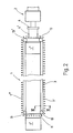
- Fig. 1 shows a schematic representation of a spinning machine (1) which is arranged next to a winding machine (2).
- the spinning and winding machines used today are characterized by high throughput and a high degree of automation. For this reason, an efficient transport system is required to remove the spinning bobbins and to feed the bobbin tubes.
- a belt (3) is arranged on the double-sided spinning machine (1), which is guided over both machine sides.
- the formed as an endless, flexible steel belt (3) serves to remove the spinning spools (7 ') and to feed the spool sleeves (7 ⁇ ) to the spindles of the spinning machine (1).
- the conveyor belt (3) with deflection rollers (13) around both machine sides of the spinning machine (1) serves as the drive roller of the conveyor belt (3) and is connected to a drive unit, not shown in the drawing.
- the band (3) is on the one hand around the end frame (1 ⁇ ) of the spinning machine (1) and on the other hand in the area of the end frame (1 ') through an opening (11) in the frame Spinning machine (1) performed.
- a gripping device (4) which is arranged between the spinning machine (1) and the winding machine (2), serves to remove the spinning bobbins (7 ') and to feed the bobbin tubes (7 ⁇ ) to the belt (3).
- the belt (3) is guided upright on both sides of the machine on supports (5) which are fastened horizontally to the spinning machine (1).
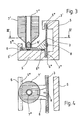
- Fig. 3 the carrier (5) is shown in section.
- the carrier (5) has an approximately L-shaped cross section.
- slot-shaped guides (5 ⁇ ) are provided one above the other in one plane.
- the edges (3 ', 3 ⁇ ) of the band (3) are guided in these guides (5 ⁇ ).
- Receptacles (6) which are made of plastic, are fastened to the band (3) by means of screws (8).
- the receptacles (6) have on their underside sliding parts (6 ⁇ ) which rest on a sliding surface (5 ') of the horizontal leg of the carrier (5).
- the receptacle (6) is guided on the side facing away from the band (3) in a further slot-shaped guide (5 ′′′).
- a pin (6 ') is provided for fastening the spinning bobbin (7') and the bobbin tube (7 ⁇ ).
- the pin (6 ') is shaped so that on the one hand a secure fixation of the spinning bobbin (7') and the bobbin tube (7 ⁇ ) is achieved and on the other hand a removal or supply is possible without any problems.
- drivers (9) are attached to the upright belt (3), which serve to transport plates (10).
- plates (10) are known in textile technology and have pins (10 ') for receiving spinning bobbins (7 ') and bobbin tubes (7 ⁇ ).
- the plates (10) lie on a horizontal sliding surface (5 ') of the carrier (5).
- the drivers (9) have receiving surfaces (9 ') which are adapted to the shape of the plate (10).
- the distance between the carriers (9) is selected so that the plates (10) are fixed between two carriers (9), so that there is no need for further guidance on the carrier (5).
- This form of training of the subject matter of the invention is particularly suitable for combination with other transport systems known in textile technology.
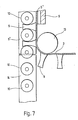
- a conveyor belt (14) is positioned in the region of a deflecting roller (13) of the conveyor belt (3).
- the conveyor belt (14) is arranged at the level of the sliding surface (5 ') of the carrier (5), so that the plates (10) can be removed from the sliding surface (5') onto the surface of the conveyor belt (14).
- the gripping device (4) is provided with gripping pins engaging in the sleeves of the spinning bobbins (7 '), it is necessary that the sleeves are guided as precisely as possible. It can then happen that the sleeves are attached to the pin (10 ') of the plate (10) with a seat causing a force fit.
- the drivers (9) and / or the carrier (5) are provided with elements which overlap the plates (10), which can have the shape of tabs located above the plate (10).
Landscapes
- Engineering & Computer Science (AREA)
- Mechanical Engineering (AREA)
- Textile Engineering (AREA)
- Spinning Or Twisting Of Yarns (AREA)
- Replacing, Conveying, And Pick-Finding For Filamentary Materials (AREA)
Applications Claiming Priority (2)
| Application Number | Priority Date | Filing Date | Title |
|---|---|---|---|
| DE3812342A DE3812342C2 (de) | 1988-04-14 | 1988-04-14 | Transportvorrichtung zum Bereitstellen von leeren Spulenhülsen und zum Abtransport von vollen Spinnspulen an einer doppelseitigen Spinnmaschine |
| DE3812342 | 1988-04-14 |
Publications (2)
| Publication Number | Publication Date |
|---|---|
| EP0337126A1 true EP0337126A1 (fr) | 1989-10-18 |
| EP0337126B1 EP0337126B1 (fr) | 1993-11-10 |
Family
ID=6351920
Family Applications (1)
| Application Number | Title | Priority Date | Filing Date |
|---|---|---|---|
| EP89104327A Expired - Lifetime EP0337126B1 (fr) | 1988-04-14 | 1989-03-11 | Dispositif de transport pour agencer des tubes de bobines et pour emporter des bobines pour un métier à filer bilateral |
Country Status (4)
| Country | Link |
|---|---|
| US (1) | US4964269A (fr) |
| EP (1) | EP0337126B1 (fr) |
| JP (1) | JP2777816B2 (fr) |
| DE (2) | DE3812342C2 (fr) |
Cited By (5)
| Publication number | Priority date | Publication date | Assignee | Title |
|---|---|---|---|---|
| EP0410120A1 (fr) * | 1989-07-26 | 1991-01-30 | Zinser Textilmaschinen GmbH | Dispositif de transport |
| EP0401667A3 (fr) * | 1989-06-09 | 1991-07-17 | Zinser Textilmaschinen GmbH | Dispositif de transport pour approvisionner des tubes de bobines vides et pour emporter des bobines pleines |
| EP0386437A3 (fr) * | 1989-03-09 | 1991-07-24 | Zinser Textilmaschinen GmbH | Dispositif pour mettre en place des tubes de bobines et pour transporter des bobines à un métier à filer à anneaux |
| EP0453889A1 (fr) * | 1990-04-24 | 1991-10-30 | Maschinenfabrik Rieter Ag | Dispositif pour transporter des bobines de mèche pleines et vides entre le cantre d'un métier à filer à anneaux et une station de transfert |
| EP0450379A3 (en) * | 1990-04-03 | 1991-11-06 | Maschinenfabrik Rieter Ag | Spinning machine, in particular ring spinning machine |
Families Citing this family (16)
| Publication number | Priority date | Publication date | Assignee | Title |
|---|---|---|---|---|
| EP0450661B1 (fr) * | 1988-09-24 | 1995-05-17 | Maschinenfabrik Rieter Ag | Métier à filer |
| CH678720A5 (fr) * | 1988-09-24 | 1991-10-31 | Rieter Ag Maschf | |
| US5177949A (en) * | 1989-06-09 | 1993-01-12 | Zinser Textilmaschinen Gmbh | Apparatus for transporting bobbin tubes of a textile machine |
| US5179829A (en) * | 1989-06-15 | 1993-01-19 | W. Schlafhorst Ag & Co. | Combined textile yarn spinning and winding system having spinning tube transporting means |
| DE3924713C2 (de) * | 1989-07-26 | 2001-08-23 | Zinser Textilmaschinen Gmbh | Transportvorrichtung |
| DE3924711A1 (de) * | 1989-07-26 | 1991-01-31 | Zinser Textilmaschinen Gmbh | Transportvorrichtung zum bereitstellen von leeren spulenhuelsen an spinnstellen und zum abtransportieren von vollen spinnspulen von spinnstellen einer doppelseitigen spinnmaschine, insbesondere einer ringspinnmaschine |
| DE58909221D1 (de) * | 1989-09-21 | 1995-06-08 | Rieter Ag Maschf | Fördervorrichtung an einer Spinnmaschine. |
| DE4010730A1 (de) * | 1989-09-21 | 1991-04-04 | Rieter Ag Maschf | Spinnmaschine, insbesondere ringspinnmaschine |
| DE4011220A1 (de) * | 1990-04-06 | 1991-10-10 | Schlafhorst & Co W | Automatische textilmaschine mit einer mehrzahl nebeneinander angeordneter arbeitsstellen |
| DE4019100A1 (de) * | 1990-06-15 | 1991-12-19 | Schlafhorst & Co W | Transporteinrichtung fuer voneinander unabhaengige paletten, die spulen oder spulenhuelsen tragen |
| DE4031768A1 (de) * | 1990-10-06 | 1992-04-09 | Zinser Textilmaschinen Gmbh | Verfahren zum abtransportieren voller spulen und zum zufuehren leerer spulenhuelsen sowie spinnmaschine |
| DE4129537C2 (de) * | 1991-09-05 | 2000-01-27 | Rieter Ag Maschf | Transportsystem zur Beförderung von Voll- und Leerhülsen bei Spinn- und Spulmaschinen |
| DE4324039A1 (de) * | 1993-07-17 | 1995-01-19 | Schlafhorst & Co W | Transportsystem an einer Topfspinnmaschine |
| DE4420039B4 (de) * | 1993-07-23 | 2004-01-29 | Maschinenfabrik Rieter Ag | Spinnmaschine |
| DE4343019C2 (de) * | 1993-12-16 | 1998-02-12 | Zinser Textilmaschinen Gmbh | Vorrichtung zum Zuführen und Abführen von Hülsen und Spulen für eine Spinn- oder Zwirnmaschine |
| IT1272873B (it) * | 1995-01-10 | 1997-07-01 | Savio Macchine Tessili Srl | Sistema di distribuzione e movimentazione delle spole alle stazioni di roccatura di una roccatrice automatica |
Citations (5)
| Publication number | Priority date | Publication date | Assignee | Title |
|---|---|---|---|---|
| GB333238A (en) * | 1929-02-06 | 1930-08-06 | Alfred Seeley | Improvements in machines for winding or winding and also doubling or twisting or otherwise operating upon or using yarns or threads and in slubbing frames, intermediate frames, roving frames, ring spinning machines and ring doubling machines and other analogous machines for preparing, spinning and doubling fibrous materials |
| DE565372C (de) * | 1930-03-22 | 1932-11-29 | Schlafhorst & Co W | Spulmaschine mit einem den Fadenablaufstellen entlang laufenden endlosen Foerdermittel |
| CH545866A (fr) * | 1971-02-22 | 1974-02-15 | ||
| EP0061432A1 (fr) * | 1981-03-25 | 1982-09-29 | Officine Savio S.p.A. | Dispositif pour le transport de bobines |
| DE3341895A1 (de) * | 1983-11-19 | 1985-05-30 | W. Schlafhorst & Co, 4050 Mönchengladbach | Spinn-/spul-aggregat |
Family Cites Families (11)
| Publication number | Priority date | Publication date | Assignee | Title |
|---|---|---|---|---|
| DE502149C (de) * | 1929-02-12 | 1930-07-09 | Charles Schrans | Vorrichtung zum selbsttaetigen Auswechseln der vollen Spulen gegen leere Spulenhuelsen fuer Spinnmaschinen |
| DE618082C (de) * | 1931-12-24 | 1935-09-02 | Schlafhorst & Co W | Vorrichtung zum Auswechseln einer Gruppe bewickelter Spulen gegen leere Huelsen an spindellosen Koetzerspulmaschinen |
| DE1535070B2 (de) * | 1965-12-16 | 1973-10-18 | Zinser Textilmaschinen Gmbh, 7333 Ebersbach | Transportvorrichtung für Spulenwechselvorrichtungen an Spinn- und Zwirnmaschinen |
| GB1170660A (en) * | 1967-07-01 | 1969-11-12 | Giddings & Lewis Fraser Ltd | Magazine for Supplying Bobbins to a Winding Machine |
| DE2816418C2 (de) * | 1978-04-15 | 1985-03-28 | Fritz 7347 Bad Überkingen Stahlecker | Offenend-Spinnmaschine mit einer Spulenwechseleinrichtung |
| JPS5938469Y2 (ja) * | 1980-05-16 | 1984-10-26 | 豊和工業株式会社 | ボビン移送装置 |
| US4463909A (en) * | 1981-04-10 | 1984-08-07 | Murata Kikai Kabushiki Kaisha | Cop supplying system in automatic winder |
| JPS5982433A (ja) * | 1982-11-02 | 1984-05-12 | Toyoda Autom Loom Works Ltd | 粗紡機における管替え方法及びその装置 |
| US4681231A (en) * | 1982-12-08 | 1987-07-21 | Murata Kikai Kabushiki Kaisha | Article selecting and conveying system |
| DE3345825A1 (de) * | 1983-12-17 | 1985-06-27 | W. Schlafhorst & Co, 4050 Mönchengladbach | Pufferspeicher eines kopsvorbereitungsaggregates |
| US4813222A (en) * | 1987-04-09 | 1989-03-21 | Kabushiki Kaisha Toyoda Jidoshokki Seisakusho | System for transferring full and empty bobbins from and to a textile machine such as a ring spinning frame |
-
1988
- 1988-04-14 DE DE3812342A patent/DE3812342C2/de not_active Expired - Fee Related
-
1989
- 1989-03-11 EP EP89104327A patent/EP0337126B1/fr not_active Expired - Lifetime
- 1989-03-11 DE DE89104327T patent/DE58906131D1/de not_active Expired - Fee Related
- 1989-04-11 US US07/336,242 patent/US4964269A/en not_active Expired - Fee Related
- 1989-04-14 JP JP1093301A patent/JP2777816B2/ja not_active Expired - Fee Related
Patent Citations (5)
| Publication number | Priority date | Publication date | Assignee | Title |
|---|---|---|---|---|
| GB333238A (en) * | 1929-02-06 | 1930-08-06 | Alfred Seeley | Improvements in machines for winding or winding and also doubling or twisting or otherwise operating upon or using yarns or threads and in slubbing frames, intermediate frames, roving frames, ring spinning machines and ring doubling machines and other analogous machines for preparing, spinning and doubling fibrous materials |
| DE565372C (de) * | 1930-03-22 | 1932-11-29 | Schlafhorst & Co W | Spulmaschine mit einem den Fadenablaufstellen entlang laufenden endlosen Foerdermittel |
| CH545866A (fr) * | 1971-02-22 | 1974-02-15 | ||
| EP0061432A1 (fr) * | 1981-03-25 | 1982-09-29 | Officine Savio S.p.A. | Dispositif pour le transport de bobines |
| DE3341895A1 (de) * | 1983-11-19 | 1985-05-30 | W. Schlafhorst & Co, 4050 Mönchengladbach | Spinn-/spul-aggregat |
Cited By (5)
| Publication number | Priority date | Publication date | Assignee | Title |
|---|---|---|---|---|
| EP0386437A3 (fr) * | 1989-03-09 | 1991-07-24 | Zinser Textilmaschinen GmbH | Dispositif pour mettre en place des tubes de bobines et pour transporter des bobines à un métier à filer à anneaux |
| EP0401667A3 (fr) * | 1989-06-09 | 1991-07-17 | Zinser Textilmaschinen GmbH | Dispositif de transport pour approvisionner des tubes de bobines vides et pour emporter des bobines pleines |
| EP0410120A1 (fr) * | 1989-07-26 | 1991-01-30 | Zinser Textilmaschinen GmbH | Dispositif de transport |
| EP0450379A3 (en) * | 1990-04-03 | 1991-11-06 | Maschinenfabrik Rieter Ag | Spinning machine, in particular ring spinning machine |
| EP0453889A1 (fr) * | 1990-04-24 | 1991-10-30 | Maschinenfabrik Rieter Ag | Dispositif pour transporter des bobines de mèche pleines et vides entre le cantre d'un métier à filer à anneaux et une station de transfert |
Also Published As
| Publication number | Publication date |
|---|---|
| EP0337126B1 (fr) | 1993-11-10 |
| JP2777816B2 (ja) | 1998-07-23 |
| JPH01299169A (ja) | 1989-12-01 |
| US4964269A (en) | 1990-10-23 |
| DE3812342C2 (de) | 1994-08-11 |
| DE3812342A1 (de) | 1989-10-26 |
| DE58906131D1 (de) | 1993-12-16 |
Similar Documents
| Publication | Publication Date | Title |
|---|---|---|
| EP0337126B1 (fr) | Dispositif de transport pour agencer des tubes de bobines et pour emporter des bobines pour un métier à filer bilateral | |
| DE3630670C2 (fr) | ||
| DE1560348A1 (de) | Transporteinrichtung einer selbsttaetigen Huelsenwechseleinrichtung | |
| DE1256122B (de) | Automatische Spulmaschine mit in einer Geraden angeordneten Spulstellen | |
| DE68919916T2 (de) | Einrichtung zum Transport von Spulen in einer mit einer Spulmaschine kombinierten Spinnmaschine. | |
| DE10029492C2 (de) | Schäranlage und Schärverfahren | |
| DE3150825C2 (de) | Vorrichtung zum Führen von Banknoten in einer Banknoten-Handhabungsmaschine | |
| DE4338552A1 (de) | Kreuzspulen herstellende Textilmaschine mit einer Vielzahl von in Reihe angeordneten Spulstellen | |
| DE2051471B2 (de) | Vorrichtung für die Zuführung von Schußfäden zu einer Kettenwirkmaschine | |
| DE3877418T2 (de) | Drahtziehmaschine. | |
| DE4402143A1 (de) | Vorrichtung zum Ent- und Versorgen einer Kreuzspulen herstellenden Maschine | |
| DE3033188C2 (de) | Vorrichtung zum Abwickeln von Bahnmaterial von einer Vorratswickelrolle | |
| EP0401667B1 (fr) | Dispositif de transport pour approvisionner des tubes de bobines vides et pour emporter des bobines pleines | |
| EP0646669B1 (fr) | Dispositif pour le transfert sélectif de lisses | |
| EP0468198B1 (fr) | Retordeuse, notamment retordeuse à double torsion | |
| DE102007031151A1 (de) | Luftspinnmaschine | |
| DE69020250T2 (de) | Vorrichtung zur Übergabe von Spulen in Spinnmaschinen. | |
| DE2064227C3 (de) | Vorrichtung für die Zuführung von Schußfäden zu einer Kettenwirkmaschine | |
| DE3732796A1 (de) | Vorrichtung zum entfernen von vorgespinst-resten von spulen | |
| EP0410120B1 (fr) | Dispositif de transport | |
| DE2311021A1 (de) | Fadenfuehrer | |
| DE3021121C2 (de) | Vorrichtung zum Auflegen und Spannen eines Endlosriemens einer Spinn- und Zwirnmaschine | |
| DE202019101925U1 (de) | Vorrichtung zum Fördern einer Materialbahn | |
| DE3739850C2 (de) | Fadentraversiervorrichtung | |
| DE3531034A1 (de) | Verfahren und vorrichtung zum changieren aufzuspulender garne und faeden |
Legal Events
| Date | Code | Title | Description |
|---|---|---|---|
| PUAI | Public reference made under article 153(3) epc to a published international application that has entered the european phase |
Free format text: ORIGINAL CODE: 0009012 |
|
| AK | Designated contracting states |
Kind code of ref document: A1 Designated state(s): CH DE FR IT LI |
|
| 17P | Request for examination filed |
Effective date: 19891118 |
|
| 17Q | First examination report despatched |
Effective date: 19910603 |
|
| ITF | It: translation for a ep patent filed | ||
| GRAA | (expected) grant |
Free format text: ORIGINAL CODE: 0009210 |
|
| AK | Designated contracting states |
Kind code of ref document: B1 Designated state(s): CH DE FR IT LI |
|
| ET | Fr: translation filed | ||
| REF | Corresponds to: |
Ref document number: 58906131 Country of ref document: DE Date of ref document: 19931216 |
|
| PLBE | No opposition filed within time limit |
Free format text: ORIGINAL CODE: 0009261 |
|
| STAA | Information on the status of an ep patent application or granted ep patent |
Free format text: STATUS: NO OPPOSITION FILED WITHIN TIME LIMIT |
|
| 26N | No opposition filed | ||
| PGFP | Annual fee paid to national office [announced via postgrant information from national office to epo] |
Ref country code: FR Payment date: 20020322 Year of fee payment: 14 |
|
| PG25 | Lapsed in a contracting state [announced via postgrant information from national office to epo] |
Ref country code: FR Free format text: LAPSE BECAUSE OF NON-PAYMENT OF DUE FEES Effective date: 20031127 |
|
| REG | Reference to a national code |
Ref country code: FR Ref legal event code: ST |
|
| PGFP | Annual fee paid to national office [announced via postgrant information from national office to epo] |
Ref country code: DE Payment date: 20060513 Year of fee payment: 18 |
|
| PGFP | Annual fee paid to national office [announced via postgrant information from national office to epo] |
Ref country code: CH Payment date: 20070326 Year of fee payment: 19 |
|
| PGFP | Annual fee paid to national office [announced via postgrant information from national office to epo] |
Ref country code: IT Payment date: 20070615 Year of fee payment: 19 |
|
| PG25 | Lapsed in a contracting state [announced via postgrant information from national office to epo] |
Ref country code: DE Free format text: LAPSE BECAUSE OF NON-PAYMENT OF DUE FEES Effective date: 20071002 |
|
| REG | Reference to a national code |
Ref country code: CH Ref legal event code: PL |
|
| PG25 | Lapsed in a contracting state [announced via postgrant information from national office to epo] |
Ref country code: LI Free format text: LAPSE BECAUSE OF NON-PAYMENT OF DUE FEES Effective date: 20080331 Ref country code: CH Free format text: LAPSE BECAUSE OF NON-PAYMENT OF DUE FEES Effective date: 20080331 |
|
| PG25 | Lapsed in a contracting state [announced via postgrant information from national office to epo] |
Ref country code: IT Free format text: LAPSE BECAUSE OF NON-PAYMENT OF DUE FEES Effective date: 20080311 |