EP0410120A1 - Dispositif de transport - Google Patents
Dispositif de transport Download PDFInfo
- Publication number
- EP0410120A1 EP0410120A1 EP90110938A EP90110938A EP0410120A1 EP 0410120 A1 EP0410120 A1 EP 0410120A1 EP 90110938 A EP90110938 A EP 90110938A EP 90110938 A EP90110938 A EP 90110938A EP 0410120 A1 EP0410120 A1 EP 0410120A1
- Authority
- EP
- European Patent Office
- Prior art keywords
- drivers
- transport
- plates
- plate
- spinning
- Prior art date
- Legal status (The legal status is an assumption and is not a legal conclusion. Google has not performed a legal analysis and makes no representation as to the accuracy of the status listed.)
- Granted
Links
- 238000009987 spinning Methods 0.000 claims abstract description 33
- 238000007378 ring spinning Methods 0.000 claims description 9
- 230000032258 transport Effects 0.000 description 39
- 239000000969 carrier Substances 0.000 description 5
- 229910000831 Steel Inorganic materials 0.000 description 2
- 239000010959 steel Substances 0.000 description 2
- 238000012546 transfer Methods 0.000 description 2
- 238000010276 construction Methods 0.000 description 1
- 238000013461 design Methods 0.000 description 1
- 238000011161 development Methods 0.000 description 1
- 238000007599 discharging Methods 0.000 description 1
- 238000003780 insertion Methods 0.000 description 1
- 230000037431 insertion Effects 0.000 description 1
- 238000000034 method Methods 0.000 description 1
- 239000013589 supplement Substances 0.000 description 1
- 230000007704 transition Effects 0.000 description 1
Images


Classifications
-
- D—TEXTILES; PAPER
- D01—NATURAL OR MAN-MADE THREADS OR FIBRES; SPINNING
- D01H—SPINNING OR TWISTING
- D01H9/00—Arrangements for replacing or removing bobbins, cores, receptacles, or completed packages at paying-out or take-up stations ; Combination of spinning-winding machine
- D01H9/18—Arrangements for replacing or removing bobbins, cores, receptacles, or completed packages at paying-out or take-up stations ; Combination of spinning-winding machine for supplying bobbins, cores, receptacles, or completed packages to, or transporting from, paying-out or take-up stations ; Arrangements to prevent unwinding of roving from roving bobbins
- D01H9/187—Arrangements for replacing or removing bobbins, cores, receptacles, or completed packages at paying-out or take-up stations ; Combination of spinning-winding machine for supplying bobbins, cores, receptacles, or completed packages to, or transporting from, paying-out or take-up stations ; Arrangements to prevent unwinding of roving from roving bobbins on individual supports, e.g. pallets
Definitions
- the invention relates to a transport device for providing empty bobbin tubes at the spinning stations and for removing full spools from the spinning units of a double-sided spinning machine, in particular a ring spinning machine, with a driven transport means, which is arranged in the region of the spinning station and with drivers for each bobbin tube or a plate accommodating a spinning bobbin is provided, the drivers aligning the plates at a distance corresponding to the spindle pitch.
- transport elements are provided on both sides of the spinning machine, which are driven to move back and forth. These transport elements are equipped with drivers that only take the plates in one direction, so that these plates are aligned with the spinning positions so that they are in the correct position for an automatic bobbin change.
- the plates are guided on a U-shaped guide track arranged around the spinning machine, which is connected at one end of the machine to an infeed point and an outfeed point for the plates.
- the transport device contains a means of transport which is designed as an upright, endless steel belt which is guided by means of guides and / or deflection rollers over both machine sides of the spinning machine.
- the drivers arranged on the conveyor belt transport pegged plates into the area of the spinning positions of the spinning machine, the plates sliding on a guideway.
- the pins of the plates are designed to receive bobbin tubes or spinning bobbins.
- the drivers align the plates at a distance corresponding to the spindle pitch, which enables the transfer or takeover of bobbin tubes or spinning bobbins by means of an automatic changing device.
- the drivers are designed as a support element for the plates, with receivers for the plates being provided on the drivers.
- the drivers are provided with guide elements which are slidably guided in a guide track arranged on the longitudinal sides of the spinning machine.
- the guideway has a leading edge on which the pins of the plates are guided.
- the invention has for its object to provide a transport device of the type mentioned so that an exact alignment of the plates is guaranteed in a row.
- This object is achieved in a generic transport device in that an endless means of transport guided around the area of the spinning stations is provided, that the drivers are provided with recesses, each with a recess of the leading and the subsequent driver to a receptacle for one Supplement plates, and that the drivers are provided with guide surfaces which are arranged in the transport direction on opposite sides of the plates so that the guide surfaces of two consecutive drivers form a border for one plate each.
- a transport device designed in this way has a particularly simple construction, since there are no separate guideways for the plates, since these are carried by the drivers. For this purpose, recesses are provided on the drivers, which receive and carry the plates in the transport position. Furthermore, the carrier designed as a support element ensures that the plates are transported in a particularly safe and low-friction manner. In order to achieve an exact alignment of the plates, guide surfaces are provided on the carriers, which align the plates in a row in the area of the spinning positions. A plate is positioned by the guide surfaces of two successive drivers, these guide surfaces forming an enclosure for the plate.
- the endless means of transport provided in the subject matter of the invention is particularly economical since only one drive unit is required.
- the guide surfaces are assigned to a pin which protrudes from the respective plate. It is advantageous here if the pin is provided with a collar against which the guide surfaces of successive drivers rest.
- An advantageous development of the invention provides that the guide surfaces of each driver are arranged offset to the transport direction in such a way that the guide surface leading in the transport direction lies on the inside with respect to a deflection point and the subsequent guide surface is on the outside.
- the plate arranged between two drivers is thus guided diagonally, as a result of which an exact and stable positioning takes place, in particular, transverse to the direction of transport.
- the guide surfaces are designed as a section of a cylindrical surface, the diameter of which is adapted to the diameter of the pin of the plate. This creates a large contact surface for the guide surface, which on the one hand achieves a firm hold and on the other hand does not show any signs of wear.
- plates of different sizes can be used as long as only the pins have the same diameter.
- a convexly curved guide surface adjoins the guide surface leading in the transport direction, the distance from the transport means increasing starting at the guide surface and transversely to the transport direction. This ensures automatic removal of the plates from the transport device in the area of a discharge point for the plates. Additional means for discharging the plates are therefore not necessary.
- the drivers are provided with essentially horizontal receiving surfaces for the plates.
- the drivers are provided with pins for receiving full spinning bobbins or empty bobbin tubes. This eliminates the need for additional devices for the intermediate positioning of spinning bobbins or bobbin tubes during the changing process.
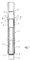
- the ring spinning machine (10) shown schematically in FIG. 1 has spinning positions (11, 12) on both machine sides, which are arranged between the machine end frames (13, 14).
- An endless, driven belt (15) is guided around the spinning positions (11, 12) of the ring spinning machine (10) and is designed as an upright, flexible steel belt.
- deflection wheels (16, 17, 18, 19) are provided, on which the belt (15) is deflected.
- At least one of the gear wheels (16, 17, 18, 19) is connected to a drive unit, not shown in the drawing.
- plates (20) are guided to and from the spinning positions (11, 12) of the ring spinning machine (10).
- an entry and exit point (21, 22) are provided for the plates (20).
- the plates (20) can be fed to the insertion point (21) or the plates (20) can be removed from the discharge point (22) by means of a conveyor belt (23, 24).
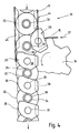
- FIG. 2 shows the transport device in the area of the discharge point (22).
- Carriers (25) are attached at a distance from one another on the upright arranged belt (15) of the transport device, which have a foot part (26) according to FIG. 3, which is fastened to the belt (15) by means of a fastening element (50).
- the foot part (26) of the driver (25) is designed as a guide element which, together with a guide element (not shown in the drawing) arranged on the opposite side of the conveyor belt, is slidably guided in a guide path (not shown).
- the drivers are supported on the guideway in horizontal and vertical directions.
- the upper part of the drivers (25) is U-shaped in cross section and has a support plate (27) underneath and a guide plate (28) arranged above it, which are connected to one another via a vertically arranged connecting part (29).
- the spaced support and guide plates (27, 28) of adjacent drivers (25) form recesses (30) for receiving the base plate (31) of a plate (20) accommodated in between.
- the receiving surfaces (32) of the support plates (27) are arranged horizontally.
- the height of the recesses (30) provided on the drivers (25) is designed such that the plates (20) between them can be easily fed in and out.
- the carriers (25) designed as support elements enable the plates (20) to be transported safely and with little friction.
- Pins (33) protrude from the guide plates (28) of the drivers (25), which are designed in the same way as the pins (34) of the plates (20). In the transport position of the plates (20), the pins (33) of the drivers (25) and the pins (34) of the plates (20) are arranged at the same height.
- guide surfaces (35, 36) are provided, which are arranged in the transport direction in the direction of arrow (37) on opposite sides of the driver (25), that the guide surfaces (35, 36) of two successive drivers form an enclosure for one plate (20).
- the guide surfaces (35, 36) of the successive drivers rest on a collar (38) of the pin (34) of the plate (20) with a larger diameter.
- the guide surfaces (35, 36) of each driver (25) are arranged so offset that the leading in the transport direction guide surface (35) with respect to the guide wheel (18) is inside and the subsequent guide surface (36) outside .
- the plate (20) is guided, as it were, diagonally, as a result of which good fixation is achieved, in particular transversely to the direction of transport.
- the guide surfaces (35, 36) provided on the carriers (25) align the plates (20) transported by the transport device in a row in the region of the spinning positions (11, 12) of the ring spinning machine (10). This improves the takeover of full spinning bobbins or the transfer of empty bobbin tubes by means of an automatic changing device, not shown in the drawing, since the pins (34) of the plates (20) and the pins (33) of the drivers (25) are in a straight line are arranged.
- the guide surfaces (35, 36) provided on the side surfaces of the guide plate (28) of each driver (25) are designed as a section of a cylindrical surface, the diameter of which is adapted to the collar (38) of the plate pin (34).
- the transport device is thus able to align plates (20) exactly regardless of the diameter of the base plate (31).
- a convexly curved guide surface (40) is provided on the carriers (25) of the transport device, the design of which is particularly clear from the carrier (25) arranged in the region of the deflection wheel (18) in FIG. 2, which does not transport a plate (20).
- the guide surface (40) adjoins the concave guide surface (35) leading in the transport direction. Accordingly, the guide plate (28) of the driver (25) is S-shaped at its front edge. The distance from the belt (15) increases starting from the guide surface (35) and transversely to the transport direction (37). This ensures that the transport in the area of the discharge point (22) device is discharged with its collar (38) along the guide surface (40) sliding plate (20).
- a sluice device (44) designed in principle the same way as the discharge device (43) has guide rails (45, 46) on which the plates (20) are brought up.
- the conveyor belt (23) connected to the infeed device (44) exerts pressure on the plates (20) that are ready.
- a plate (20) standing at the front is thus guided between two successive drivers (25) and received between them.
- the plate (20) slides on the one hand on the outer guide rail (46) of the infeed device (44) and on the receiving surfaces (32) of the carrier plates (27) of the drivers (25).
- the collar (38) of the plate pin (34) is finally fixed between the guide surfaces (35, 36) of successive drivers (25).
Landscapes
- Engineering & Computer Science (AREA)
- Mechanical Engineering (AREA)
- Textile Engineering (AREA)
- Replacing, Conveying, And Pick-Finding For Filamentary Materials (AREA)
- Spinning Or Twisting Of Yarns (AREA)
- Specific Conveyance Elements (AREA)
- Special Conveying (AREA)
- Belt Conveyors (AREA)
- Chain Conveyers (AREA)
Applications Claiming Priority (2)
| Application Number | Priority Date | Filing Date | Title |
|---|---|---|---|
| DE3924710A DE3924710A1 (de) | 1989-07-26 | 1989-07-26 | Transportvorrichtung |
| DE3924710 | 1989-07-26 |
Publications (2)
| Publication Number | Publication Date |
|---|---|
| EP0410120A1 true EP0410120A1 (fr) | 1991-01-30 |
| EP0410120B1 EP0410120B1 (fr) | 1993-01-13 |
Family
ID=6385874
Family Applications (1)
| Application Number | Title | Priority Date | Filing Date |
|---|---|---|---|
| EP90110938A Expired - Lifetime EP0410120B1 (fr) | 1989-07-26 | 1990-06-09 | Dispositif de transport |
Country Status (4)
| Country | Link |
|---|---|
| US (1) | US5103627A (fr) |
| EP (1) | EP0410120B1 (fr) |
| JP (1) | JPH0737301B2 (fr) |
| DE (2) | DE3924710A1 (fr) |
Families Citing this family (4)
| Publication number | Priority date | Publication date | Assignee | Title |
|---|---|---|---|---|
| US5337551A (en) * | 1989-06-15 | 1994-08-16 | W. Schlafhorst Ag & Co. | Textile machine tube transport assembly with full package and empty tube capability |
| DE4129537C2 (de) * | 1991-09-05 | 2000-01-27 | Rieter Ag Maschf | Transportsystem zur Beförderung von Voll- und Leerhülsen bei Spinn- und Spulmaschinen |
| US5775067A (en) * | 1997-01-08 | 1998-07-07 | Riverwood International Corporation | Article selector wedge |
| DE19755973A1 (de) * | 1997-12-16 | 1999-06-17 | Rieter Ag Maschf | Transporteinrichtung für Spinnmaschine |
Citations (4)
| Publication number | Priority date | Publication date | Assignee | Title |
|---|---|---|---|---|
| FR1517543A (fr) * | 1966-04-04 | 1968-03-15 | Kurashiki Spinning Co | Procédé et appareil pour transférer automatiquement des canettes de fil filé entre un métier à filer et un bobinoir automatique |
| DE3712027A1 (de) * | 1986-04-11 | 1987-10-22 | Toyoda Automatic Loom Works | Verfahren und vorrichtung zum transportieren von vollen spulen und leeren spulenkernen bei einer textilmaschine |
| EP0337126A1 (fr) * | 1988-04-14 | 1989-10-18 | Zinser Textilmaschinen GmbH | Dispositif de transport pour agencer des tubes de bobines et pour emporter des bobines pour un métier à filer bilateral |
| WO1990003461A1 (fr) * | 1988-09-24 | 1990-04-05 | Maschinenfabrik Rieter Ag | Metier a filer |
Family Cites Families (7)
| Publication number | Priority date | Publication date | Assignee | Title |
|---|---|---|---|---|
| US3307340A (en) * | 1963-04-01 | 1967-03-07 | To Yo Da Automatic Loom Works | Apparatus for continuously effecting automatic bobbin exchange on spinning machine |
| GB1170660A (en) * | 1967-07-01 | 1969-11-12 | Giddings & Lewis Fraser Ltd | Magazine for Supplying Bobbins to a Winding Machine |
| US4325479A (en) * | 1976-11-09 | 1982-04-20 | Camillo Pirovano | Feed conveyor |
| DE3341895A1 (de) * | 1983-11-19 | 1985-05-30 | W. Schlafhorst & Co, 4050 Mönchengladbach | Spinn-/spul-aggregat |
| FR2560655B1 (fr) * | 1984-03-02 | 1987-02-13 | Geoffroy Henri | Poulie pour appareil de manutention continue |
| WO1986001475A1 (fr) * | 1984-09-03 | 1986-03-13 | Harald Krogsrud | Dispositif de remorquage de charge |
| DE3618857C2 (de) * | 1986-06-04 | 1996-08-14 | Truetzschler Gmbh & Co Kg | Vorrichtung zum fliegenden Wechsel von Spinnkannen für eine Spinnereivorbereitungsmaschine |
-
1989
- 1989-07-26 DE DE3924710A patent/DE3924710A1/de not_active Withdrawn
-
1990
- 1990-06-09 EP EP90110938A patent/EP0410120B1/fr not_active Expired - Lifetime
- 1990-06-09 DE DE9090110938T patent/DE59000752D1/de not_active Expired - Fee Related
- 1990-07-17 US US07/554,251 patent/US5103627A/en not_active Expired - Fee Related
- 1990-07-26 JP JP2196412A patent/JPH0737301B2/ja not_active Expired - Lifetime
Patent Citations (4)
| Publication number | Priority date | Publication date | Assignee | Title |
|---|---|---|---|---|
| FR1517543A (fr) * | 1966-04-04 | 1968-03-15 | Kurashiki Spinning Co | Procédé et appareil pour transférer automatiquement des canettes de fil filé entre un métier à filer et un bobinoir automatique |
| DE3712027A1 (de) * | 1986-04-11 | 1987-10-22 | Toyoda Automatic Loom Works | Verfahren und vorrichtung zum transportieren von vollen spulen und leeren spulenkernen bei einer textilmaschine |
| EP0337126A1 (fr) * | 1988-04-14 | 1989-10-18 | Zinser Textilmaschinen GmbH | Dispositif de transport pour agencer des tubes de bobines et pour emporter des bobines pour un métier à filer bilateral |
| WO1990003461A1 (fr) * | 1988-09-24 | 1990-04-05 | Maschinenfabrik Rieter Ag | Metier a filer |
Also Published As
| Publication number | Publication date |
|---|---|
| DE59000752D1 (de) | 1993-02-25 |
| JPH0737301B2 (ja) | 1995-04-26 |
| DE3924710A1 (de) | 1991-01-31 |
| US5103627A (en) | 1992-04-14 |
| EP0410120B1 (fr) | 1993-01-13 |
| JPH0379565A (ja) | 1991-04-04 |
Similar Documents
| Publication | Publication Date | Title |
|---|---|---|
| EP0337126B1 (fr) | Dispositif de transport pour agencer des tubes de bobines et pour emporter des bobines pour un métier à filer bilateral | |
| DE60207790T2 (de) | Umreifungsmaschine | |
| EP1140691B1 (fr) | Dispositif de transport de bouteilles | |
| EP3652096A1 (fr) | Dispositif de stockage et de convoyeur et procédé de fonctionnement du dispositif de stockage et de convoyeur | |
| CH678720A5 (fr) | ||
| EP0427222A2 (fr) | Appareil pour la fabrication de plaques d'impression | |
| DE3928648A1 (de) | Anlage mit einer oder mehreren spinnmaschinen und mit wenigstens einem wechselwagen zum wechseln von kannen | |
| EP0380930B1 (fr) | Système de transport suspendu | |
| EP0410120B1 (fr) | Dispositif de transport | |
| EP0504442A1 (fr) | Dispositif pour l'alimentation des pièces vers une machine de production | |
| EP0401667B1 (fr) | Dispositif de transport pour approvisionner des tubes de bobines vides et pour emporter des bobines pleines | |
| DE4402143A1 (de) | Vorrichtung zum Ent- und Versorgen einer Kreuzspulen herstellenden Maschine | |
| DE3908462A1 (de) | Spinnmaschine mit spulenwechslern | |
| DE69708183T2 (de) | Maschine zum Befüllen von Behältern mit Flüssigkeiten | |
| CH691490A5 (de) | Transport- und Umsetzanlage zwischen mindestens einer Vorspinnmaschine und einem nachgeordneten Lager- oder Verarbeitungsbereich. | |
| EP0418418B1 (fr) | Dispositif de transport dans un métier à filer | |
| EP0410121B1 (fr) | Dispositif de transport pour l'alimentation et l'enlèvement de bobines vides et pleines aux postes de filature d'un métier à filer double-côté, en particulier de filature d'un métier à filer à anneaux | |
| EP0521034B1 (fr) | Installation servant a transporter une liasse de billets ou des objets similaires d'une station collectrice a une station distributrice | |
| DE4129537A1 (de) | Transportsystem zur befoerderung von voll- und leerhuelsen bei spinn- und spulmaschinen | |
| EP0451477A2 (fr) | Dispositif de remplacement automatique de bobines de mèche vides avec bobines de mèche pleines dans un râtelier à bobines d'un métier à filer à anneaux | |
| DE69402667T2 (de) | Maschine zum Anbringen von hülsenförmigen Etiketten insbesondere auf Flaschen | |
| DE4127292C2 (de) | Verfahren und Vorrichtung zum Transport mindestens einer Kanne in einer Spinnerei | |
| DE4205197C2 (de) | Vorrichtung zum Einfüllen von Füllgut in eine Hülle, insbesondere einen Briefumschlag | |
| DE60202649T2 (de) | Etikettenmagazin, insbesondere für Etikettiermaschinen | |
| DE4319173A1 (de) | Ringspinnmaschine bei der längs auf beiden Seiten der Maschine vorhandener Spindelreihen zum Zuführen von Leerhülsen und Abführen von Kopsen antreibbare Transportbänder angeordnet sind |
Legal Events
| Date | Code | Title | Description |
|---|---|---|---|
| PUAI | Public reference made under article 153(3) epc to a published international application that has entered the european phase |
Free format text: ORIGINAL CODE: 0009012 |
|
| AK | Designated contracting states |
Kind code of ref document: A1 Designated state(s): CH DE FR IT LI |
|
| 17P | Request for examination filed |
Effective date: 19901214 |
|
| 17Q | First examination report despatched |
Effective date: 19920617 |
|
| ITF | It: translation for a ep patent filed | ||
| GRAA | (expected) grant |
Free format text: ORIGINAL CODE: 0009210 |
|
| AK | Designated contracting states |
Kind code of ref document: B1 Designated state(s): CH DE FR IT LI |
|
| ET | Fr: translation filed | ||
| REF | Corresponds to: |
Ref document number: 59000752 Country of ref document: DE Date of ref document: 19930225 |
|
| PLBE | No opposition filed within time limit |
Free format text: ORIGINAL CODE: 0009261 |
|
| STAA | Information on the status of an ep patent application or granted ep patent |
Free format text: STATUS: NO OPPOSITION FILED WITHIN TIME LIMIT |
|
| 26N | No opposition filed | ||
| PGFP | Annual fee paid to national office [announced via postgrant information from national office to epo] |
Ref country code: FR Payment date: 20000615 Year of fee payment: 11 |
|
| PGFP | Annual fee paid to national office [announced via postgrant information from national office to epo] |
Ref country code: CH Payment date: 20000705 Year of fee payment: 11 |
|
| PGFP | Annual fee paid to national office [announced via postgrant information from national office to epo] |
Ref country code: DE Payment date: 20000731 Year of fee payment: 11 |
|
| PG25 | Lapsed in a contracting state [announced via postgrant information from national office to epo] |
Ref country code: LI Free format text: LAPSE BECAUSE OF NON-PAYMENT OF DUE FEES Effective date: 20010630 Ref country code: CH Free format text: LAPSE BECAUSE OF NON-PAYMENT OF DUE FEES Effective date: 20010630 |
|
| REG | Reference to a national code |
Ref country code: CH Ref legal event code: PL |
|
| PG25 | Lapsed in a contracting state [announced via postgrant information from national office to epo] |
Ref country code: FR Free format text: LAPSE BECAUSE OF NON-PAYMENT OF DUE FEES Effective date: 20020228 |
|
| PG25 | Lapsed in a contracting state [announced via postgrant information from national office to epo] |
Ref country code: DE Free format text: LAPSE BECAUSE OF NON-PAYMENT OF DUE FEES Effective date: 20020403 |
|
| PG25 | Lapsed in a contracting state [announced via postgrant information from national office to epo] |
Ref country code: IT Free format text: LAPSE BECAUSE OF NON-PAYMENT OF DUE FEES;WARNING: LAPSES OF ITALIAN PATENTS WITH EFFECTIVE DATE BEFORE 2007 MAY HAVE OCCURRED AT ANY TIME BEFORE 2007. THE CORRECT EFFECTIVE DATE MAY BE DIFFERENT FROM THE ONE RECORDED. Effective date: 20050609 |