EP0337169A2 - Machine d'impression au tampon - Google Patents
Machine d'impression au tampon Download PDFInfo
- Publication number
- EP0337169A2 EP0337169A2 EP89105102A EP89105102A EP0337169A2 EP 0337169 A2 EP0337169 A2 EP 0337169A2 EP 89105102 A EP89105102 A EP 89105102A EP 89105102 A EP89105102 A EP 89105102A EP 0337169 A2 EP0337169 A2 EP 0337169A2
- Authority
- EP
- European Patent Office
- Prior art keywords
- hollow profile
- profile section
- printing machine
- pressure
- pad printing
- Prior art date
- Legal status (The legal status is an assumption and is not a legal conclusion. Google has not performed a legal analysis and makes no representation as to the accuracy of the status listed.)
- Withdrawn
Links
- 238000007649 pad printing Methods 0.000 title claims abstract description 22
- 239000000463 material Substances 0.000 claims description 8
- 238000003780 insertion Methods 0.000 claims description 6
- 230000037431 insertion Effects 0.000 claims description 6
- 229910000906 Bronze Inorganic materials 0.000 claims description 3
- 239000010974 bronze Substances 0.000 claims description 3
- KUNSUQLRTQLHQQ-UHFFFAOYSA-N copper tin Chemical compound [Cu].[Sn] KUNSUQLRTQLHQQ-UHFFFAOYSA-N 0.000 claims description 3
- 238000007639 printing Methods 0.000 abstract description 9
- 239000003973 paint Substances 0.000 abstract description 6
- 238000000034 method Methods 0.000 description 5
- 238000003754 machining Methods 0.000 description 2
- 238000004040 coloring Methods 0.000 description 1
- 230000008878 coupling Effects 0.000 description 1
- 238000010168 coupling process Methods 0.000 description 1
- 238000005859 coupling reaction Methods 0.000 description 1
- 239000002184 metal Substances 0.000 description 1
Images
Classifications
-
- B—PERFORMING OPERATIONS; TRANSPORTING
- B41—PRINTING; LINING MACHINES; TYPEWRITERS; STAMPS
- B41F—PRINTING MACHINES OR PRESSES
- B41F17/00—Printing apparatus or machines of special types or for particular purposes, not otherwise provided for
- B41F17/001—Pad printing apparatus or machines
Definitions
- the invention relates to a pad printing machine with a cliché support with cliché that can be displaced by means of an adjusting device in the machine frame, on which a color-absorbing hollow body is supported, in which the hollow body is held under pressure on the cliché support by means of a printing cylinder, in which the cliché support with the Cliché is slidable under an adjustable tampon and the object to be printed can be placed under the tampon.
- a pad printing machine of this type is known from DE-GM 83 27 911. So that the cliché is clearly colored by the hollow body and the excess ink is wiped clean, in this known pad printing machine at least part of the end face of the hollow body supported on the cliché carrier is made of hard material and is designed as a wiping edge. For this hard scraper edge to work properly, the surface of the cliché must also be finely machined. This processing is very complex and satisfactory results can only be achieved if both the scraper edge and the cliché are made of hard metal. Sufficiently satisfactory results are not achieved with a plastic cliché.
- the hollow body is firmly connected to that of a device which generates the predetermined contact pressure between the hollow body and the cliché, so that this device must also be pivoted in order to fill the hollow body with color.
- the hollow body designed as a hollow profile section is circumferentially coupled to a drive device which rotates the hollow profile section from time to time at least by a predetermined angular range.
- the drive device is simply coupled to the hollow profile section by means of friction.
- This easily detachable coupling facilitates handling and brings about a simple design of the pad printing machine.
- the drive device can be stationary and can be coupled to the hollow profile section in the starting position. It has proven to be expedient for the drive device to transmit a predetermined rotational movement to the hollow profile section at the same time intervals. The time intervals can be based on the cycle of the printing process, so that the hollow section is rotated after each inking process.
- a hollow profile section without fine machining of the scraper edge can be avoided in that the hollow body is designed as a hollow profile section in which at least the area of the end face supported on the cliché support consists of elastic deformable material which, from the point of view of low friction compared to the material of the cliché support and the Clichés is selected that the end of the hollow profile section facing away from the cliché holder is closed by means of a pressure plate with a fitting section adapted to the cavity of the hollow profile section, that the pressure plate has a central spherical cup in which a spherical cap of a pressure stamp is supported, and that the pressure stamp is supported by a pressure cylinder is pressed against the pressure plate.
- the hollow body With its elastic, deformable end face, the hollow body is supported on the cliché and cliché support in such a way that the cliché is clearly colored and excess color is stripped off.
- the cliché does not need to have a finely machined surface, since the end face of the hollow profile section uniquely and finally engages the cliché over the entire circumference.
- the hollow profile section can also be produced very inexpensively, since it does not require any fine machining either. If the pressure cylinder is reset, the printing plate releases the face of the hollow profile section facing away from the cliché, so that color can easily be poured into the free-standing hollow profile section on the cliché holder.
- the articulated connection between the pressure stamp and the pressure plate allows compensating movements for the hollow profile section, so that it can always adapt to the surface of the plate and the plate holder.
- one embodiment provides that the Fitting section of the pressure plate merges into a conically tapering insertion section.
- the parts become particularly simple and inexpensive if the configuration is made such that the hollow profile section, the pressure plate, the fitting section and the insertion section have a round cross section.
- the stripping of excess ink from the cliché is further improved in that the cross section of the cavity of the hollow profile section widens conically towards the end face supported on the cliché carrier and forms a supporting edge.
- a tight seal of the hollow profile section can be achieved in that the pressure plate has a diameter that corresponds to the outer diameter of the hollow profile section, and that the fitting section of the pressure plate has a diameter that corresponds to the inner diameter of the hollow profile section.
- the device for generating the contact pressure between the hollow section and the plate or plate holder is particularly simple if it is provided that the machine frame has a stand and a base plate, that the pressure stamp is guided in a vertically adjustable manner in a stamp housing attached to the stand, and that the stamp housing also the preferably hydraulically or pneumatically controllable pressure cylinder is connected, the pressure ram being coupled to the piston rod of the pressure cylinder.
- a further embodiment provides that the pressure stamp with the free
- the end of the spherical cap is captively attached to the pressure plate through the spherical cap, but is mounted on all sides in the pressure plate so that it can be pivoted to a limited extent.
- a further embodiment provides that the inside diameter of the hollow profile section is larger than the largest dimension of the image engraved in the cliché.
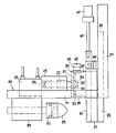
- the machine frame 10 of the pad printing machine has the stand 11 and the base plate 12.
- the plate holder 13 with the plate 17 used can be adjusted on the base plate 12.
- the plate holder 13 is guided with the guide bar 29 in the guide receptacle 30 of the base plate 12.
- the piston rod 15 of the actuating cylinder 14 is articulated on the driver 16 of the plate carrier 13.
- the actuating cylinder 14 is preferably hydraulically or pneumatically controllable and has two end positions. In one end position, which is shown in the drawing, the cliché 17 is below the tampon 28, which is attached to the tampon holder 27.
- the tampon holder 27 is adjustably guided with a guide rod in the guide housing 26, which is firmly connected to the stand 11. The movements of the tampon 28 takes over an actuating device, not shown, acting on the guide rod, for example another actuating cylinder.
- the plate holder 13 In the other end position of the actuating cylinder 14, the plate holder 13 is displaced to the right so far that the plate 17 is enclosed by the hollow body designed as a hollow profile section 18.
- the end face 19 of the hollow profile section 18, which is supported on the plate carrier 13 with contact pressure, consists of elastic, deformable material, e.g. Plastic or bronze.
- the entire hollow profile section 18 is advantageously produced from this material.
- the cross section of the hollow profile section 18 is round and the inner cross section widens conically towards the end face 19, so that a circumferential elastic, deformable scraper edge is formed, which can easily adapt to the surface of the plate 17 and the plate holder 13.
- the choice of material for the cliché 17, the cliché carrier 13 and the hollow profile section 18 is made such that the smallest possible friction occurs when the cliché carrier 13 is adjusted under the hollow profile section 18.
- the contact pressure for the hollow profile section 18 is generated by the pressure cylinder 25, which can be controlled hydraulically or pneumatically.
- the piston rod 28 of the pressure cylinder 25 is coupled to the pressure stamp 23, which is guided in a vertically adjustable manner in the stamp housing 24.
- the stamp housing 24 is firmly connected to the stand 11 and the pressure cylinder 25.
- the lower end of the plunger 23 carries the spherical cap 31, which is adjustable to a limited extent on all sides in the spherical cap 32 of the pressure plate 20.
- the screw 33 holds the pressure plate 20 captively on the pressure stamp 23.
- the round pressure plate 20 has a diameter which corresponds to the outer diameter of the hollow profile section 18.
- the fitting section 21 and the conical insertion section 22 are integrally formed on the pressure plate 20.
- the fitting section 21 has a diameter which corresponds to the inner diameter of the hollow profile section 18.
- the conical insertion section 22 facilitates centering when the pressure plate 20 is placed on it, so that the pressure plate 20 covers and closes the hollow profile section 18 flush.
- the pressure cylinder 25 presses the hollow profile section 18 against the printing plate support 13 via the pressure plate 20.
- the elastic, deformable end face 19 adapts to the surface of the printing plate 17 and the printing plate support 13, so that no color beneath the end face which acts as a wiping edge leaves the hollow profile section 18.
- the articulated connection from the spherical cap 31 and the spherical socket 32 allows the hollow profile section 18 to be pivoted in all directions with respect to the rigidly guided pressure ram 23, so that the hollow profile section 18 with the end face 19 also adapt to larger deviations in the surface of the plate 17 and the plate carrier 13 can, if it has an inclination to the horizontal in one direction or the other.
- the pressure cylinder 25 is returned to its starting position, then the pressure plate 20 is raised from the upper end face of the hollow profile section 18 via the pressure stamp 23.
- the hollow end section 18 remains with its lower end face 19 on the plate holder 13, so that color and any required thinning can easily be refilled into the hollow section section 18.
- the pressure cylinder 25 is brought back into the working position in order to transmit the predetermined contact pressure to the hollow profile section 18 again via the pressure ram 23 and the pressure plate 20.
- a drive device 34 is assigned to the hollow profile section 18, which can transmit a rotary movement to the hollow profile section 18, as indicated by the axis of rotation 35.
- the drive device 34 can be coupled to the circumference of the hollow profile section 18 by means of friction, which can be done most simply by means of a friction wheel. From time to time, the hollow profile section 18 is rotated by the drive device 34 at least by a predetermined angular range. This rotation of the hollow profile section 18 can run synchronously with the printing cycle, so that the hollow profile section is rotated after each coloring process. However, the time intervals can also be chosen arbitrarily, as can the angle of rotation of the hollow profile section 18.
- the drive device 18 leaves attach firmly to the machine frame of the pad printing machine and is easily detachably connected to the hollow profile section 18 so that it can be easily removed.
Landscapes
- Printing Methods (AREA)
Applications Claiming Priority (2)
| Application Number | Priority Date | Filing Date | Title |
|---|---|---|---|
| DE3812344 | 1988-04-14 | ||
| DE3812344 | 1988-04-14 |
Publications (2)
| Publication Number | Publication Date |
|---|---|
| EP0337169A2 true EP0337169A2 (fr) | 1989-10-18 |
| EP0337169A3 EP0337169A3 (fr) | 1990-07-04 |
Family
ID=6351922
Family Applications (1)
| Application Number | Title | Priority Date | Filing Date |
|---|---|---|---|
| EP89105102A Withdrawn EP0337169A3 (fr) | 1988-04-14 | 1989-03-22 | Machine d'impression au tampon |
Country Status (1)
| Country | Link |
|---|---|
| EP (1) | EP0337169A3 (fr) |
Cited By (2)
| Publication number | Priority date | Publication date | Assignee | Title |
|---|---|---|---|---|
| CN104760408A (zh) * | 2015-03-30 | 2015-07-08 | 海盐欧亚特汽配有限公司 | 一种刹车片自动印字装置 |
| CN108839426A (zh) * | 2018-09-28 | 2018-11-20 | 天津尚吉液压设备有限公司 | 微型工业移印机 |
Family Cites Families (1)
| Publication number | Priority date | Publication date | Assignee | Title |
|---|---|---|---|---|
| DE8327911U1 (de) * | 1983-09-29 | 1987-12-03 | Philipp, Wilfried, 7014 Kornwestheim | Tampondruckmaschine |
-
1989
- 1989-03-22 EP EP89105102A patent/EP0337169A3/fr not_active Withdrawn
Cited By (2)
| Publication number | Priority date | Publication date | Assignee | Title |
|---|---|---|---|---|
| CN104760408A (zh) * | 2015-03-30 | 2015-07-08 | 海盐欧亚特汽配有限公司 | 一种刹车片自动印字装置 |
| CN108839426A (zh) * | 2018-09-28 | 2018-11-20 | 天津尚吉液压设备有限公司 | 微型工业移印机 |
Also Published As
| Publication number | Publication date |
|---|---|
| EP0337169A3 (fr) | 1990-07-04 |
Similar Documents
| Publication | Publication Date | Title |
|---|---|---|
| DE3335230C2 (fr) | ||
| DE19718113C2 (de) | Rakelvorrichtung zum Siebdrucken | |
| EP0422350A2 (fr) | Dispositif encrier | |
| DE69517824T2 (de) | Verfahren und vorrichtung zum abgeben eines viskosen materials | |
| DE3102139C2 (de) | Farbwerk für eine Rotationsdruckmaschine | |
| DE2205430A1 (de) | Gerät zum Einfärben eines Druck-Klischees | |
| DE2023951C3 (de) | Reinigungsvorrichtung für den Wischzylinder einer Stichdruckmaschine | |
| DE2819846A1 (de) | Abstreifeinrichtung | |
| DE68907775T2 (de) | Druckmaschine mit einem rotierenden Tampon für das Drucken auf dem Rand von Autofenstern. | |
| DE69202816T2 (de) | Farbzufuhreinrichtung. | |
| DE4213669C2 (de) | Vorrichtung zur Anstellung einer Kammerrakel | |
| DE4129946C2 (de) | Tampondruckmaschine | |
| DE69835725T2 (de) | Verfahren und Vorrichtung zum Einfärben einer Druckplatte mit einem Farbbehälter | |
| DE3932232A1 (de) | Rakelvorrichtung | |
| DE4031706C2 (de) | Vorrichtung zum Beschriften einer gewölbten Fläche eines Werkstückes | |
| DE8331501U1 (de) | Farbgeber fuer eine tampondruckmaschine | |
| EP1147888A1 (fr) | Machine à imprimer avec des essuyeurs attachés aux bords du cylindre porte-gravure | |
| DE3225564A1 (de) | Lackierwerk fuer eine mit eindruckwerk ausgeruestete offsetdruckmaschine | |
| EP0537649A1 (fr) | Machine d'impression à tampon avec dispositif d'encrage fermé | |
| DE4244378C2 (de) | Druckmaschine zum Bedrucken ebener oder geformter Oberflächen von Gegenständen | |
| EP0894049B1 (fr) | Machine a imprimer a tampon encreur | |
| DE8804891U1 (de) | Tampondruckmaschine | |
| DE1067448B (fr) | ||
| DE8116618U1 (de) | Tampon-druckmaschine | |
| EP0655327A1 (fr) | Dispositif d'encrage pour l'impression en creux |
Legal Events
| Date | Code | Title | Description |
|---|---|---|---|
| PUAI | Public reference made under article 153(3) epc to a published international application that has entered the european phase |
Free format text: ORIGINAL CODE: 0009012 |
|
| AK | Designated contracting states |
Kind code of ref document: A2 Designated state(s): AT CH DE FR GB LI NL SE |
|
| PUAL | Search report despatched |
Free format text: ORIGINAL CODE: 0009013 |
|
| AK | Designated contracting states |
Kind code of ref document: A3 Designated state(s): AT CH DE FR GB LI NL SE |
|
| 17P | Request for examination filed |
Effective date: 19900718 |
|
| 17Q | First examination report despatched |
Effective date: 19920518 |
|
| STAA | Information on the status of an ep patent application or granted ep patent |
Free format text: STATUS: THE APPLICATION IS DEEMED TO BE WITHDRAWN |
|
| 18D | Application deemed to be withdrawn |
Effective date: 19921001 |