EP0337366B1 - Verfahren und Vorrichtung zur nichtlinearen Regelung eines Innenverbrennungsmotors - Google Patents
Verfahren und Vorrichtung zur nichtlinearen Regelung eines Innenverbrennungsmotors Download PDFInfo
- Publication number
- EP0337366B1 EP0337366B1 EP89106348A EP89106348A EP0337366B1 EP 0337366 B1 EP0337366 B1 EP 0337366B1 EP 89106348 A EP89106348 A EP 89106348A EP 89106348 A EP89106348 A EP 89106348A EP 0337366 B1 EP0337366 B1 EP 0337366B1
- Authority
- EP
- European Patent Office
- Prior art keywords
- engine
- denotes
- pressure
- intake air
- equation
- Prior art date
- Legal status (The legal status is an assumption and is not a legal conclusion. Google has not performed a legal analysis and makes no representation as to the accuracy of the status listed.)
- Expired - Lifetime
Links
- 238000000034 method Methods 0.000 title claims description 15
- 238000002485 combustion reaction Methods 0.000 title claims description 11
- 238000002474 experimental method Methods 0.000 claims description 9
- 230000003190 augmentative effect Effects 0.000 claims description 5
- 230000008859 change Effects 0.000 claims description 5
- 238000005086 pumping Methods 0.000 claims description 2
- 238000004364 calculation method Methods 0.000 description 12
- 238000010586 diagram Methods 0.000 description 4
- 230000004044 response Effects 0.000 description 4
- 238000001514 detection method Methods 0.000 description 3
- 239000011159 matrix material Substances 0.000 description 3
- 230000004043 responsiveness Effects 0.000 description 3
- 238000009472 formulation Methods 0.000 description 2
- 239000000203 mixture Substances 0.000 description 2
- 230000008569 process Effects 0.000 description 2
- 238000011144 upstream manufacturing Methods 0.000 description 2
- XLYOFNOQVPJJNP-UHFFFAOYSA-N water Substances O XLYOFNOQVPJJNP-UHFFFAOYSA-N 0.000 description 2
- 230000008901 benefit Effects 0.000 description 1
- 230000005540 biological transmission Effects 0.000 description 1
- 238000010276 construction Methods 0.000 description 1
- 230000007423 decrease Effects 0.000 description 1
- 238000006073 displacement reaction Methods 0.000 description 1
- 230000002708 enhancing effect Effects 0.000 description 1
- 239000000446 fuel Substances 0.000 description 1
- 238000010348 incorporation Methods 0.000 description 1
- 238000002347 injection Methods 0.000 description 1
- 239000007924 injection Substances 0.000 description 1
- 238000002360 preparation method Methods 0.000 description 1
- 238000012545 processing Methods 0.000 description 1
- 230000010349 pulsation Effects 0.000 description 1
- 230000003068 static effect Effects 0.000 description 1
- 208000006379 syphilis Diseases 0.000 description 1
- 238000012360 testing method Methods 0.000 description 1
Images


Classifications
-
- F—MECHANICAL ENGINEERING; LIGHTING; HEATING; WEAPONS; BLASTING
- F02—COMBUSTION ENGINES; HOT-GAS OR COMBUSTION-PRODUCT ENGINE PLANTS
- F02D—CONTROLLING COMBUSTION ENGINES
- F02D41/00—Electrical control of supply of combustible mixture or its constituents
- F02D41/02—Circuit arrangements for generating control signals
- F02D41/14—Introducing closed-loop corrections
- F02D41/1438—Introducing closed-loop corrections using means for determining characteristics of the combustion gases; Sensors therefor
- F02D41/1444—Introducing closed-loop corrections using means for determining characteristics of the combustion gases; Sensors therefor characterised by the characteristics of the combustion gases
- F02D41/1448—Introducing closed-loop corrections using means for determining characteristics of the combustion gases; Sensors therefor characterised by the characteristics of the combustion gases the characteristics being an exhaust gas pressure
-
- F—MECHANICAL ENGINEERING; LIGHTING; HEATING; WEAPONS; BLASTING
- F02—COMBUSTION ENGINES; HOT-GAS OR COMBUSTION-PRODUCT ENGINE PLANTS
- F02D—CONTROLLING COMBUSTION ENGINES
- F02D41/00—Electrical control of supply of combustible mixture or its constituents
- F02D41/02—Circuit arrangements for generating control signals
- F02D41/14—Introducing closed-loop corrections
- F02D41/1401—Introducing closed-loop corrections characterised by the control or regulation method
- F02D2041/1413—Controller structures or design
- F02D2041/1415—Controller structures or design using a state feedback or a state space representation
-
- F—MECHANICAL ENGINEERING; LIGHTING; HEATING; WEAPONS; BLASTING
- F02—COMBUSTION ENGINES; HOT-GAS OR COMBUSTION-PRODUCT ENGINE PLANTS
- F02D—CONTROLLING COMBUSTION ENGINES
- F02D41/00—Electrical control of supply of combustible mixture or its constituents
- F02D41/02—Circuit arrangements for generating control signals
- F02D41/14—Introducing closed-loop corrections
- F02D41/1401—Introducing closed-loop corrections characterised by the control or regulation method
- F02D2041/1413—Controller structures or design
- F02D2041/143—Controller structures or design the control loop including a non-linear model or compensator
-
- F—MECHANICAL ENGINEERING; LIGHTING; HEATING; WEAPONS; BLASTING
- F02—COMBUSTION ENGINES; HOT-GAS OR COMBUSTION-PRODUCT ENGINE PLANTS
- F02D—CONTROLLING COMBUSTION ENGINES
- F02D41/00—Electrical control of supply of combustible mixture or its constituents
- F02D41/02—Circuit arrangements for generating control signals
- F02D41/14—Introducing closed-loop corrections
- F02D41/1401—Introducing closed-loop corrections characterised by the control or regulation method
- F02D2041/1433—Introducing closed-loop corrections characterised by the control or regulation method using a model or simulation of the system
-
- F—MECHANICAL ENGINEERING; LIGHTING; HEATING; WEAPONS; BLASTING
- F02—COMBUSTION ENGINES; HOT-GAS OR COMBUSTION-PRODUCT ENGINE PLANTS
- F02D—CONTROLLING COMBUSTION ENGINES
- F02D2200/00—Input parameters for engine control
- F02D2200/02—Input parameters for engine control the parameters being related to the engine
- F02D2200/10—Parameters related to the engine output, e.g. engine torque or engine speed
- F02D2200/1002—Output torque
- F02D2200/1004—Estimation of the output torque
-
- F—MECHANICAL ENGINEERING; LIGHTING; HEATING; WEAPONS; BLASTING
- F02—COMBUSTION ENGINES; HOT-GAS OR COMBUSTION-PRODUCT ENGINE PLANTS
- F02D—CONTROLLING COMBUSTION ENGINES
- F02D2200/00—Input parameters for engine control
- F02D2200/02—Input parameters for engine control the parameters being related to the engine
- F02D2200/10—Parameters related to the engine output, e.g. engine torque or engine speed
- F02D2200/1006—Engine torque losses, e.g. friction or pumping losses or losses caused by external loads of accessories
Definitions
- the present invention relates to a nonlinear feedback control apparatus for an internal combustion engine and a feedback control method for executing feedback control of the operating state of the engine so that the rotation speed of the engine becomes stable and converges to a target rotation speed.
- a proposed prior-art engine control apparatus and method are based on linear control theory.
- the prior art thus assures the stability and responsiveness of the control.
- a dynamic model of the engine including actuators and sensors is constructed by a linear approximation of the dynamic behavior of the engine. Based on the rotation speed of the model engine, the actual rotation speed of the real engine is controlled.
- the model of the engine is constructed using the linear approximation of the engine behavior, and system identification.
- This prior-art engine control system has the following problems when the engine is constructed based on the model.
- the operating state of the engine includes a warming-up state, states where the load applied to the engine is large or small, states where the rotation speed of the engine is fast or slow, and various other states. These operating states vary widely. Such a complicated behavior of the engine cannot be determined based on the behavior of the engine model.
- multiple models of the engine are constructed according to-the various operating states of the engine.
- the model of behavior approximating that of the controlled engine is selected from the multiple models.
- the multiple models make the control system intricate, thus delaying the response of the system.
- changes in the control system when the selected model changes to another model cannot be predicted. This prior art cannot really work.
- intermediate document EP-A-0 287 932 discloses a nonlinear feedback method and controller for an internal combustion engine which corresponds to the nonlinear feedback contol method and apparatus as claimed in claims 1 and 4 defined hereinafter except for features relating to determination of deviations that are unmeasurable factors between the actual engine operation and the modeled behaviour of the engine according to the intake pressure of the intake air and the engine speed and to incorporation of such deviations into a motion equation and a mass conservation equation.
- this object is accomplished by a method according to claim 1 and by an apparatus according to claim 4.
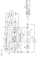
- an engine controller 1 comprises a four-cylinder engine 2 and an electronic control unit (hereinafter referred to as "ECU") 3 that controls the engine 2.
- ECU electronice control unit
- the engine 2 has a first combustion chamber 4 which comprises a cylinder 4a and a piston 4b, and second to fourth combustion chambers 5, 6, and 7 with the same arrangement as in the first combustion chamber 4.
- the combustion chambers 4, 5, 6 and 7 communicate with intake ports 12, 13, 14 and 15 through intake valves 8, 9, 1 0 and 11, respectively.
- a surge tank 16, which absorbs pulsation of intake air, is provided at the upstream position of the intake ports 12, 13, 14, and 15.
- a throttle valve 18 is disposed inside an intake pipe 17 that is provided in the upstream portion of the surge tank 16.
- the throttle valve 18 is activated by a motor 19.
- the motor 19 changes the opening of the throttle valve 18 and controls the amount of intake air flowing through the intake pipe 17.
- the intake pipe 17 has a throttle bypass 20 that passes across the throttle valve 18.
- An idling speed control valve (hereinafter "ISCV") 21 regulates the throttle bypass 20.
- the ISCV 21 opens or closes in response to a command signal from the ECU 3, thus adjusting the amount of intake air flowing through the throttle bypass 20.
- the engine 2 further comprises an ignition control system 22 equipped with an ignition coil, which generates the high voltage required for ignition, and a distributor 24, which distributes the high voltage generated in the ignition 22 to the respective spark plugs (not shown) of the cylinders in response to the revolution of a crankshaft 23.
- an ignition control system 22 equipped with an ignition coil, which generates the high voltage required for ignition, and a distributor 24, which distributes the high voltage generated in the ignition 22 to the respective spark plugs (not shown) of the cylinders in response to the revolution of a crankshaft 23.
- the engine controller 1 has the following sensors for detecting various parameters: an intake pressure sensor 31, which is placed on the surge tank 16 to detect a level of intake pressure; a rotation speed sensor 32, which transmits a rotation angle signal every time the camshaft of the distributor 24 rotates by 15° corresponding to one-half of a crank shaft rotation angle of 30°; a throttle position sensor 33, which detects an opening of the throttle valve 18; and an accelerator operated amount sensor 34, which detects the displacement of an accelerator pedal 34a.
- an intake pressure sensor 31 which is placed on the surge tank 16 to detect a level of intake pressure
- a rotation speed sensor 32 which transmits a rotation angle signal every time the camshaft of the distributor 24 rotates by 15° corresponding to one-half of a crank shaft rotation angle of 30°
- a throttle position sensor 33 which detects an opening of the throttle valve 18
- an accelerator operated amount sensor 34 which detects the displacement of an accelerator pedal 34a.
- the ECU 3 is a arithmetic-logic circuit mainly comprising a CPU 3a, a ROM 3b and a RAM 3c.
- the ECU 3 is connected through a common bus 3d to an input port 3e and an output port 3f to exchange data with the outside.
- the ECU 3 actuates the motor 19 and the ISCV 21 based on the detection signals transmitted from the intake pressure sensor 31, the rotation speed sensor 32, and the throttle position sensor 33, and executes feedback control in which the rotation speed of the engine 2 is controlled to coincide with a target rotation speed.
- the ECU 3 comprises single feedback controller.
- two kinds of the feedback control system that have the same control characteristics can be obtained.
- the feedback control systems in Figs. 3A and 3B are distinguished from each other by adding suffix "a" or "b" to the symbols representing the elements of the control system.
- the control systems in Figs. 3A and 3B are executed by the same aforementioned arithmetic-logic circuit, which mainly comprises the CPU 3a.
- the control systems shown in Figs. 3A and 3B consist of discrete systems that are realized by executing a series of programs shown in the flowchart in Figs. 6A and 6B.
- the control system shown in Fig. 3A is a discrete system based on the revolution speed of the engine 2.
- the control system shown in Fig. 3B is a discrete system based on the crank angle of the engine 2. As described later, in the control system of Fig.
- a rotation speed squared ⁇ 2 calculated by a first multiplying section J1a and a target rotation speed squared ⁇ r 2 calculated by a second multiplying section J2a are used, while in the control system of Fig. 3B, an actual rotation speed of the engine 2 and a target rotation speed ⁇ r are used.
- target rotation speed setting sections Ma and Mb set the target rotation speed wr, and the actual rotation speed ⁇ of the engine 2 is controlled to coincide with the target rotation speed ⁇ r.
- actual operating conditions of the engine 2 are detected by detecting the actual rotation speed ⁇ and an intake pressure P.
- the first multiplying section J1a calculates the rotation speed squared ⁇ 2 from the detected rotation speed ⁇ of the engine 2.
- the rotation speed squared ⁇ 2 is transmitted together with the detected intake pressure P into disturbance compensators Ga1 and Ga2.
- the detected rotation speed ⁇ is transmitted with the detected intake pressure P directly into the disturbance compensators Gb1 and Gb2.
- the disturbance compensators Gal (Gb1) ) and Ga2 (Gb2) formulate disturbance values ⁇ and ⁇ p reflecting deviations between the actual engine 2 and an engine model.
- functions ⁇ (P, ⁇ 2 ) and ⁇ p(P, ⁇ 2 ) of the intake pressure P and the rotation speed square ⁇ 2 are determined.
- functions ⁇ (P, ⁇ ) and ⁇ p(P, ⁇ ) of the intake pressure P and the rotation speed ⁇ are determined.
- the disturbance values are not limited to these functions. Functions of detected values representing changes in the operating conditions of the engine 2, such as water temperature in the water jacket of the engine 2, intake air temperature and atmospheric pressure are also possible.
- the calculation method could be formulation of results of testing the engine 2, formulation of results of operating a simulated engine, or interpolation using established tables.
- a linear calculation section Sa (Sb) estimates load torque Te of the engine 2 based on the rotation speed squared ⁇ 2 (the rotation speed ⁇ ), the intake pressure P, the disturbance values ⁇ and ⁇ p calculated by the disturbance compensators Ga1 (Gb1) and Ga2 (Gb2), and a variable u ⁇ (u t ) (described later).
- a regulator Ra (Rb) multiplies a determinant of the rotation speed squared ⁇ 2 (the rotation speed ⁇ ) and the intake pressure P by an optimal feedback gain F1, and executes a feedback of the rotation speed squared ⁇ 2 (the rotation speed ⁇ ) and the intake pressure P.
- a second multiplying section J2a calculates the target rotation speed squared ⁇ r 2 from the target rotation speed ⁇ r.
- An integral compensator Ia (Ib) integrally compensates for unexpected disturbance by multiplying the deviation between the target rotation speed squared ⁇ r 2 (the target rotation speed ⁇ r) and the actual rotation speed squared ⁇ 2 (the actual rotation speed ⁇ ) by an optimal feedback gain F2, and by accumulating the multiplied deviation sequentially.
- a limiter La (Lb) determines upper-limit and lower-limit values for the values calculated by the integral compensator Ia (Ib).
- the limiter La (Lb) restricts the output value from the integral compensator Ia (Ib) to the range between the upper-limit and lower-limit values, and enhances the responsiveness of the feedback control system by preventing feedback va-lues from overshooting and undershooting.
- a feedforward controller FFa determines a control input value by multiplying the target rotation speed squared ⁇ r 2 (the target rotation speed ⁇ r) to be controlled by a gain F3, and enhances the responsiveness of the control system.
- Gain calculators Ba1 (Bb1) and Ba2 (Bb2) multiply the output values from the linear calculation section Sa (Sb) and the output values from the disturbance compensators Ga1 (Gb1) and Ga2 (Gb2) by optimal feedback gains F4 and F5, respectively.
- the output values from the regulator Ra (Rb), the limiter La (Lb), the feedforward controller FFa (FFb) and the gain calculators Ba1 (Bb1) and Ba2 (Bb2) are added up to calculate the variable u ⁇ (u t ).
- the variable u ⁇ (u t ) is transmitted back to the linear calculation section Sa (Sb), and is also sent together with the disturbance value ⁇ p from the disturbance compensator Ga2 (Gb2) and the intake pressure P, into a converter Ca (Cb).
- the converter Ca (Cb) determines a throttle opening ⁇ t as a final control quantity.
- a dynamic physical model of the engine 2 for this embodiment is now described to explain the adequacy of the aforementioned construction of the engine controller 1, the calculation made by the linear calculation section Sa (Sb), and the calculation of the gains F1 through F5.
- Equation (1) The behavior of the engine 2 is precisely expressed by equation (1) for motion of the engine 2 and equation (4) for mass conservation of the intake air.
- M ⁇ (d ⁇ /dt) Ti - Te - Tf
- M denotes the inertial moment of the rotating portion of the engine 2
- Te denotes the load torque of the engine 2.
- Ti denotes the output torque expected from the pressure in the cylinder of the engine 2.
- the portion of the indicated torque Ti which portion cannot be expressed as a function of the intake pressure P alone, is formulated as a deviation. The value of this deviation ⁇ (P, ⁇ ) is determined by experiment.
- the first and second terms ( ⁇ 2 ⁇ 2 + ⁇ 3 ) on the right side of equation (3) represent a mechanical torque loss, and the third term ⁇ 4 ⁇ (P-Pa) on the right side of equation (3) represents the engine pumping pressure loss.
- Equation (7) is obtained by substituting equations (2) and (3) for equation (1), substituting equations (5) and (6) for equation (4), and solving these equations for the actual rotation speed ⁇ and the intake pressure P.
- ⁇ denotes a differential for the crank angle ⁇ .
- I denotes an identity matrix
- Equation (27) is the last row of the following equation (28).
- Equations (37) and (38) are then modified to the following equations (40) and (41).
- Y(k) Y(k-1)+ ⁇ X(k)
- equations (30) and (31) are arranged as follows: xr(k+1) ⁇ xr(k)
- the variable u(k) calculated using equation (54) corresponds to the variable u t defined by equation (9) and the variable u ⁇ defined by the equation (13).
- the variable u(k) should be converted to the throttle opening ⁇ t as the final control quantity.
- the throttle opening ⁇ t can be easily obtained by solving either of the following equations (55) and (56).
- F(P, ⁇ t) (C 2 /V) ⁇ u t + ⁇ 5 ⁇ P ⁇ ⁇ - ⁇ p
- F(P, ⁇ t) ⁇ (C 2 /V) ⁇ u ⁇ - ⁇ p ⁇
- Ta is the temperature of the intake air (i.e. the temperature of an air cleaner)
- S( ⁇ t) is an effective throttle opening area with regard to the throttle opening ⁇ t
- Pa is the discharged air pressure
- R is a gas constant. Since throttle valves have a complicated configuration, it is difficult to theoretically obtain the throttle effective opening area from a structural constant. However, by obtaining only the throttle opening ⁇ t, the throttle effective opening area can be precisely obtained. The throttle effective opening area can be experimentally obtained from the intake air continuously flowing through the throttle valve 18. As a result of experiments on the engine 2 for this embodiment, S( ⁇ t) and ⁇ t have been found to have the relationship as shown in Fig. 4.
- ⁇ is a function of a ratio (P/Pa) between the intake pressure P and the discharged-air pressure Pa.
- the value of ⁇ is obtained as follows:
- Fig. 5 shows the results of experiments for obtaining the relationship between the function ⁇ and the ratio (P/Pa).
- the mass flow mt can be precisely obtained by detecting the intake pressure P, the discharged-air pressure Pa, and the throttle opening ⁇ t.
- the throttle opening ⁇ t can be easily obtained from the mass flow mt, the intake pressure P, and the discharged-air pressure Pa.
- the first term on the right side of the equation (47) corresponds to the function of the regulators Ra and Rb.
- the second term on the right side of the equation (47) refers to the function of the integral compensators Ia and Ib.
- the converters Ca and Cb calculate the throttle opening ⁇ t, the actual control quantity, from the variables u ⁇ and ut, respectively, as illustrated in the tables corresponding in Figs. 4 and 5, and in equations (55) or (56).
- the coefficients F 1 through F 5 by which the terms in equation (54) are multiplied correspond to the feedback gains F 1 through F 5 shown in Figs. 3A and 3B.
- the coefficients F 1 through F 5 in Fig. 3A differ in their value from those in Fig. 3B.
- the aforementioned discrete control system is executed by the ECU 3.
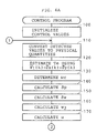
- the engine control program will be explained next with reference to the flowchart in Figs. 6A and 6B.
- the program is stored in ROM 3b.
- the CPU 3a begins and repeats this engine control program.
- step 100 initializes control values. For example, an initial value is set in the integral compensators Ia and Ib, and an initial value for the internal state quantity z is set so that the linear calculation sections Sa and Sb can make calculations.
- step 110 receives the values detected by the intake pressure sensor 31, the rotation speed sensor 32 and the other sensors for detecting the current operating state of the engine 2, and converts the detected values into the physical quantities required for the execution of control. For example, the actual rotation speed ⁇ of the engine 2 is detected, or the rotation speed squared ⁇ 2 is calculated from the rotation speed ⁇ .
- step 120 estimates the load torque Te by making a static calculation of equation (27).
- step 130 determines the target rotation speed ⁇ r of the engine 2.
- the target rotation speed ⁇ r is determined by a system where a converter ⁇ 1 calculates a vehicle target speed from an accelerator opening and the running environment of the engine 2, and a converter ⁇ 2 receives information such as the vehicle target speed calculated by the converter ⁇ 1, and a shift position and a clutch position of a transmission connected to the engine 2.
- the converter ⁇ 2 thus determines the target rotation speed ⁇ r.
- the system for determining the target rotation speed ⁇ r can be separate from the program shown in Figs. 6A and 6B, or the system can be part of the processing at step 130.
- the structure of the system is determined by the capacity of the ECU 3.
- Steps 140 and 150 calculate the disturbance values ⁇ p and ⁇ in equations (7) and (8), respectively, by searching a table for ⁇ p and ⁇ .
- the table for detecting the disturbance values is stored beforehand in the ROM 3b, based on the operating state of the engine 2 detected in step 110.
- Step 160 calculates the variable w 2t or w 2 ⁇ .
- the variables are defined by the equations (10) and (14).
- step 170 calculates the variable u(k), i.e., u t and u ⁇ using the equation (47).
- step 180 calculates the function F(P, ⁇ t) using the equations (55) and (56).
- step 190 calculates the function ⁇ from the intake-air pressure P and the discharged-air pressure Pa, using the characteristic graph in Fig. 5.
- step 200 calculates the effective throttle opening area S( ⁇ t) using these functions F(P, ⁇ t) and ⁇ according to the equation (57).
- step 210 the effective throttle opening area S( ⁇ t) is converted to the throttle opening ⁇ t, the control quantity, using the graph in Fig. 4.
- step 220 executes control by transmitting the throttle opening ⁇ t to the output section 3f of the ECU 3, and by actuating the motor 19.
- step 230 integrates the differences between control target values and actual values according to the following equation (60) which corresponds to the second term of equation (54): Se ⁇ Se + F 2 ⁇ yi - yr(i) ⁇
- Step 240 calculates the quantity z of the internal state using equation (26). One cycle of the discrete control is thus completed.
- step 250 it is determined whether the engine 2 has been stopped by a key switch (not shown) and control need not be continued. If it is determined that further control is required, the process goes back to step 110, repeating the control. If the conditions for stopping the control exist, the process ends.
- the deviations of the actual engine from the engine model can be minimized by using the measurable control quantities representing the internal state of the engine 2.
- the deviations that cannot be measured are incorporated as the disturbance values ⁇ p and ⁇ into the control system to enhance the precision of the engine model.
- the actual rotation speed can be stably controlled and can quickly converge to the target rotation speed ⁇ r.
- the load torque Te which is physically significant, is estimated for this embodiment as a variable representing the internal state of the engine 2.
- the estimated value of the load torque Te can also be used for the other control systems such as an ignition timing control system and a fuel injection volume control system.
- the control apparatus for the embodiment can thus be used effectively.
Landscapes
- Engineering & Computer Science (AREA)
- Chemical & Material Sciences (AREA)
- Combustion & Propulsion (AREA)
- Mechanical Engineering (AREA)
- General Engineering & Computer Science (AREA)
- Combined Controls Of Internal Combustion Engines (AREA)
- Electrical Control Of Air Or Fuel Supplied To Internal-Combustion Engine (AREA)
Claims (4)
- Verfahren zur nichtlinearen rückgekoppelten Steuerung einer Brennkraftmaschine, umfassend die Schritte:a) Vorbereiten eines Verhaltensmodells der Brennkraftmaschine durch Formulieren einer Bewegungsgleichung, die die Fluktuationsbewegung der Brennkraftmaschine repräsentiert:
 b) Formulieren einer Massenerhaltungsgleichung, die Fluktuationen im Ansaugluftdruck der Brennkraftmaschine während einer vorbestimmten Zeit repräsentiert, einschließlich einem Massenflussabschnitt, welcher einen nicht meßbaren Zustand der Brennkraftmaschine darstellt:
 c) Formulieren des Ausgangsdrehmoments Ti durch die folgende Gleichung:
 d) Formulieren der Massenflüsse mt und mc durch die folgenden Gleichungen:
 - Erfassen eines meßbaren Zustands der Brennkraftmaschine durch Erfassen eines Ansaugdrucks der Ansaugluft und einer Drehzahl der Brennkraftmaschine,e) Ermitteln von nicht meßbare Faktoren darstellenden Abweichungen zwischen dem tatsächlichen Betrieb der Brennkraftmaschine und dem nachgebildeten Verhalten der Brennkraftmaschine in Übereinstimmung mit dem Ansaugdruck der Ansaugluft und der Drehzahl der Brennkraftmaschine (Schritt S1, Schritte 140 und 150),f) Einbeziehen dieser Abweichungen in die Bewegungsgleichung und die Massenerhaltungsgleichung (Schritt S1),g) Abschätzen des Lastmoments Te durch entwickeln der simultanen Gleichungen der Bewegungsgleichung und der Massenerhaltungsgleichung für ein verbessertes System (Schritt S2, Schritt 120),h) Ausführen einer optimalen rückgekoppelten Steuerung der Drehzahl der Brennkraftmaschine auf der Grundlage des Ansaugdrucks der Ansaugluft, den formulierten Abweichungen und dem abgeschätzten Lastmoment (Schritt S3, Schritt 220),i) Ermitteln der Drosselklappenöffnung θt als eine Steuervariable,j) Ermitteln einer gewünschten Drehzahl der Brennkraftmaschine in Übereinstimmung mit einem Fahrzustand des Fahrzeugs,k) Ermitteln von δω(P,ω) in Übereinstimmung mit dem Ansaugdruck und der Drehzahl der Brennkraftmaschine,l) Ermitteln von δp(P,ω) in Übereinstimmung mit dem Ansaugdruck und der Drehzahl der Brennkraftmaschine,m) Ermitteln von Variablen ut, uθt auf der Grundlage des abgeschätzten Lastmoments, der gewünschten Drehzahl der Brennkraftmaschine und den Störwerten δω(P,ω), δp(P,ω), um die Drehzahl der Brennkraftmaschine in Richtung der gewünschten Drehzahl der Brennkraftmaschine nachzuführen, undn) Umwandeln der Steuervariablen ut, uθt in eine Steuergröße für die Drosselklappenöffnung θt.
 - Verfahren zur nichtlinearen rückgekoppelten Steuerung einer Brennkraftmaschine nach Anspruch 1, bei dem der Drehmomentverlust Tf durch die folgende Gleichung ausgedrückt wird:

- Verfahren zur nichtlinearen rückgekoppelten Steuerung einer Brennkraftmaschine nach Anspruch 1, bei dem der Abweichungsermittlungsschritt das experimentelle Ermitteln der Beziehung zwischen den Abweichungen und dem meßbaren Zustand der Brennkraftmaschine umfaßt.
- Vorrichtung zur nichtlinearen rückgekoppelten Steuerung zur Ausführung des Verfahrens nach Anspruch 1, umfassend:
eine Einrichtung (31, 32) zum Erfassen eines meßbaren Zustands der Brennkraftmaschine durch Erfassen eines Ansaugdrucks der Ansaugluft und einer Drehzahl der Brennkraftmaschine, und
eine Recheneinrichtung (3) zuma) Vorbereiten eines Verhaltensmodells der Brennkraftmaschine durch Formulieren einer Bewegungsgleichung, die die Fluktuationsbewegung der Brennkraftmaschine repräsentiert: b) Formulieren einer Massenerhaltungsgleichung, die Fluktuationen im Ansaugluftdruck der Brennkraftmaschine während einer vorbestimmten Zeit repräsentiert, einschließlich einem Massenflussabschnitt, welcher einen nicht meßbaren Zustand der Brennkraftmaschine darstellt:
 c) Formulieren des Ausgangsdrehmoments Ti durch die folgende Gleichung:
 d) Formulieren der Massenflüsse mt und mc durch die folgenden Gleichungen:
 e) Ermitteln von nicht meßbare Faktoren darstellenden Abweichungen zwischen dem tatsächlichen Betrieb der Brennkraftmaschine und dem nachgebildeten Verhalten der Brennkraftmaschine in Übereinstimmung mit dem Ansaugdruck der Ansaugluft und der Drehzahl der Brennkraftmaschine (Schritt S1, Schritte 140 und 150),f) Einbeziehen dieser Abweichungen in die Bewegungsgleichung und die Massenerhaltungsgleichung (Schritt S1),g) Abschätzen des Lastmoments Te durch entwickeln der simultanen Gleichungen der Bewegungsgleichung und der Massenerhaltungsgleichung für ein verbessertes System (Schritt S2, Schritt 120),h) Ausführen einer optimalen rückgekoppelten Steuerung der Drehzahl der Brennkraftmaschine auf der Grundlage des Ansaugdrucks der Ansaugluft, den formulierten Abweichungen und dem abgeschätzten Lastmoment (Schritt S3, Schritt 220),i) Ermitteln der Drosselklappenöffnung θt als eine Steuervariable,j) Ermitteln einer gewünschten Drehzahl der Brennkraftmaschine in Übereinstimmung mit einem Fahrzustand des Fahrzeugs,k) Ermitteln von δω(P,ω) in Übereinstimmung mit dem Ansaugdruck und der Drehzahl der Brennkraftmaschine,l) Ermitteln von δp(P,ω) in Übereinstimmung mit dem Ansaugdruck und der Drehzahl der Brennkraftmaschine,m) Ermitteln von Variablen ut, uθt auf der Grundlage des abgeschätzten Lastmoments, der gewünschten Drehzahl der Brennkraftmaschine und den Störwerten δω(P,ω), δp(P,ω), um die Drehzahl der Brennkraftmaschine in Richtung der gewünschten Drehzahl der Brennkraftmaschine nachzuführen,n) Umwandeln der Steuervariablen ut, uθt in eine Steuergröße für die Drosselklappenöffnung θt.
Applications Claiming Priority (2)
| Application Number | Priority Date | Filing Date | Title |
|---|---|---|---|
| JP63089739A JP2674077B2 (ja) | 1988-04-12 | 1988-04-12 | 内燃機関の非線形フィードバック制御方法 |
| JP89739/88 | 1988-04-12 |
Publications (3)
| Publication Number | Publication Date |
|---|---|
| EP0337366A2 EP0337366A2 (de) | 1989-10-18 |
| EP0337366A3 EP0337366A3 (de) | 1990-03-07 |
| EP0337366B1 true EP0337366B1 (de) | 1996-12-18 |
Family
ID=13979134
Family Applications (1)
| Application Number | Title | Priority Date | Filing Date |
|---|---|---|---|
| EP89106348A Expired - Lifetime EP0337366B1 (de) | 1988-04-12 | 1989-04-11 | Verfahren und Vorrichtung zur nichtlinearen Regelung eines Innenverbrennungsmotors |
Country Status (4)
| Country | Link |
|---|---|
| US (1) | US5010866A (de) |
| EP (1) | EP0337366B1 (de) |
| JP (1) | JP2674077B2 (de) |
| DE (1) | DE68927558T2 (de) |
Families Citing this family (25)
| Publication number | Priority date | Publication date | Assignee | Title |
|---|---|---|---|---|
| DE4005735A1 (de) * | 1990-02-23 | 1991-08-29 | Bosch Gmbh Robert | Verfahren und einrichtung zur regelung/steuerung der laufruhe einer brennkraftmaschine |
| JP2696431B2 (ja) * | 1990-12-17 | 1998-01-14 | 株式会社ユニシアジェックス | 内燃機関のアイドル回転数制御装置 |
| FR2681908A1 (fr) * | 1991-09-27 | 1993-04-02 | Peugeot | Procede de correction des parametres de controle d'un moteur a combustion interne et dispositif de mise en óoeuvre du procede. |
| JP2833935B2 (ja) * | 1992-07-10 | 1998-12-09 | 三菱電機株式会社 | 内燃機関制御装置 |
| JPH0650195A (ja) * | 1992-07-30 | 1994-02-22 | Nippondenso Co Ltd | 内燃機関の回転数制御装置 |
| US5452207A (en) * | 1992-11-09 | 1995-09-19 | Ford Motor Company | Robust torque estimation using multiple models |
| FR2703404B1 (fr) * | 1993-03-29 | 1995-06-30 | Peugeot | Procede et dispositif de controle du fonctionnement d'un moteur a combustion interne d'un vehicule automobile . |
| US5651341A (en) * | 1995-02-08 | 1997-07-29 | Mazda Motor Corporation | Control system for dynamically operative apparatuses |
| US5577474A (en) * | 1995-11-29 | 1996-11-26 | General Motors Corporation | Torque estimation for engine speed control |
| US5623906A (en) * | 1996-01-22 | 1997-04-29 | Ford Motor Company | Fixed throttle torque demand strategy |
| JP3050794B2 (ja) * | 1996-03-01 | 2000-06-12 | 富士重工業株式会社 | エンジンの制御装置 |
| DE19618691A1 (de) * | 1996-05-09 | 1997-11-13 | Bosch Gmbh Robert | Verfahren und Vorrichtung zur Steuerung einer Brennkraftmaschine |
| FR2764941B1 (fr) * | 1997-06-19 | 1999-08-27 | Renault | Procede et dispositif de controle d'un moteur a combustion interne, a allumage commande |
| GB2329713A (en) * | 1997-09-30 | 1999-03-31 | Ford Global Tech Inc | IC engine net torque calculator |
| FR2779768B1 (fr) * | 1998-06-11 | 2000-08-18 | Renault | Procede et dispositif de regulation du fonctionnement d'un moteur a combustion interne lors d'un retour en regime de ralenti |
| FR2791395B1 (fr) * | 1999-03-23 | 2002-02-15 | Peugeot Citroen Automobiles Sa | Moteur a essence a quatre temps a allumage commande, a injection directe de carburant |
| JP3758134B2 (ja) * | 2000-10-23 | 2006-03-22 | 株式会社デンソー | 内燃機関の制御装置 |
| US6553958B1 (en) * | 2001-04-11 | 2003-04-29 | Ford Global Technologies, Inc. | Adaptive torque model for internal combustion engine |
| DE10129035A1 (de) * | 2001-06-15 | 2002-12-19 | Bosch Gmbh Robert | Verfahren und Vorrichtung zur Ermittlung einer Temperaturgröße in einer Massenstromleitung |
| US6584391B2 (en) * | 2001-07-23 | 2003-06-24 | International Engine Intellectual Property Company, Llc | Engine torque calculation |
| JP2004197614A (ja) * | 2002-12-17 | 2004-07-15 | Toyota Motor Corp | 内燃機関の圧力・温度算出装置 |
| JP2005016436A (ja) * | 2003-06-26 | 2005-01-20 | Honda Motor Co Ltd | 芝刈り機用エンジンの回転数制御装置 |
| US7191583B2 (en) * | 2003-09-25 | 2007-03-20 | Honda Motor Co., Ltd. | Lawn mower control system |
| JP5091815B2 (ja) * | 2008-09-18 | 2012-12-05 | 株式会社クボタ | 作業車の搬送状態検出構造 |
| US9546605B2 (en) * | 2011-12-08 | 2017-01-17 | Toyota Jidosha Kabushiki Kaisha | Throttle control device for controlling engine torque |
Family Cites Families (16)
| Publication number | Priority date | Publication date | Assignee | Title |
|---|---|---|---|---|
| JPS578316A (en) * | 1980-06-17 | 1982-01-16 | Mitsubishi Heavy Ind Ltd | Intake device for 4-cycle internal combustion engine |
| JPS5993945A (ja) * | 1982-11-19 | 1984-05-30 | Nippon Denso Co Ltd | 内燃機関のアイドル運転制御方法 |
| JPS59120747A (ja) * | 1982-12-27 | 1984-07-12 | Nissan Motor Co Ltd | エンジンの空燃比推定装置 |
| JPS59120751A (ja) * | 1982-12-28 | 1984-07-12 | Nissan Motor Co Ltd | 内燃機関のアイドル回転速度制御方法 |
| JPS6125858A (ja) * | 1984-07-16 | 1986-02-04 | Ricoh Co Ltd | サ−マルヘツド駆動方式 |
| DE3526409A1 (de) * | 1984-08-16 | 1986-02-27 | Volkswagen AG, 3180 Wolfsburg | Schaltungsanordnung zur vermeidung ruckartiger drehmomentaenderungen im antriebsstrang eines fahrzeugs |
| JPH0697003B2 (ja) * | 1984-12-19 | 1994-11-30 | 日本電装株式会社 | 内燃機関の運転状態制御装置 |
| JPH0612093B2 (ja) * | 1985-02-19 | 1994-02-16 | 日本電装株式会社 | 内燃機関制御装置 |
| US4785780A (en) * | 1986-07-08 | 1988-11-22 | Nippondenso Co., Ltd. | Control apparatus |
| JPS6371551A (ja) * | 1986-09-12 | 1988-03-31 | Toyota Motor Corp | 内燃機関の負荷トルク推定装置 |
| JPS6375336A (ja) * | 1986-09-17 | 1988-04-05 | Toyota Motor Corp | 内燃機関の吸入空気圧力推定装置 |
| JP2564806B2 (ja) * | 1986-09-18 | 1996-12-18 | トヨタ自動車株式会社 | 内燃機関のフイ−ドバツク制御方法 |
| JPS6375338A (ja) * | 1986-09-18 | 1988-04-05 | Toyota Motor Corp | 内燃機関の同定方法 |
| JPS6375337A (ja) * | 1986-09-18 | 1988-04-05 | Toyota Motor Corp | 内燃機関の同定方法 |
| JP2564808B2 (ja) * | 1986-09-20 | 1996-12-18 | トヨタ自動車株式会社 | 内燃機関の非線形フイ−ドバツク制御方法 |
| JPH081146B2 (ja) * | 1987-04-21 | 1996-01-10 | トヨタ自動車株式会社 | 内燃機関の非線形フイ−ドバツク制御装置 |
-
1988
- 1988-04-12 JP JP63089739A patent/JP2674077B2/ja not_active Expired - Lifetime
-
1989
- 1989-04-11 DE DE68927558T patent/DE68927558T2/de not_active Expired - Lifetime
- 1989-04-11 EP EP89106348A patent/EP0337366B1/de not_active Expired - Lifetime
- 1989-04-12 US US07/337,178 patent/US5010866A/en not_active Expired - Lifetime
Also Published As
| Publication number | Publication date |
|---|---|
| DE68927558D1 (de) | 1997-01-30 |
| EP0337366A2 (de) | 1989-10-18 |
| JPH01262347A (ja) | 1989-10-19 |
| DE68927558T2 (de) | 1997-07-10 |
| US5010866A (en) | 1991-04-30 |
| JP2674077B2 (ja) | 1997-11-05 |
| EP0337366A3 (de) | 1990-03-07 |
Similar Documents
| Publication | Publication Date | Title |
|---|---|---|
| EP0337366B1 (de) | Verfahren und Vorrichtung zur nichtlinearen Regelung eines Innenverbrennungsmotors | |
| KR930002080B1 (ko) | 내연기관의 아이들회전수 제어장치 | |
| EP0185552B1 (de) | Vorrichtung zum Steuern des Betriebs eines Innenverbrennungsmotors | |
| US4860707A (en) | Non-linear feedback controller for internal combustion engine | |
| US5282449A (en) | Method and system for engine control | |
| KR100287665B1 (ko) | 내연 기관용 제어 장치 및 제어 방법 | |
| EP0670420B1 (de) | System zur Abschätzung des Luft/Kraftstoffverhältnisses für eine Brennkraftmaschine | |
| US6065449A (en) | Fuel injection control device for an internal combustion engine | |
| EP0518289B1 (de) | Vorrichtung zur Regelung der Drehzahl einer Brennkraftmaschine | |
| JP2512787B2 (ja) | 内燃機関のスロットル開度制御装置 | |
| EP1835158A2 (de) | Vorrichtung und Verfahren zur Steuerung eines Verbrennungsmotors | |
| EP1296048B1 (de) | Regelungseinrichtung für Mehrzweckmotor | |
| US4984545A (en) | Control system for internal combustion engine | |
| US5590630A (en) | Idling speed control system and the method thereof | |
| US4638778A (en) | Idle speed control apparatus for internal combustion engine | |
| JP2564806B2 (ja) | 内燃機関のフイ−ドバツク制御方法 | |
| EP1624173B1 (de) | Methode zur Motordrehmomentberechnung | |
| EP0456616B1 (de) | Methode und Ausrüstung zur Steuerung der Leerlaufdrehzahl einer Innenbrennkraftmaschine | |
| EP0332119B1 (de) | Elektronisches Motor-Steuerungsverfahren | |
| JP2564808B2 (ja) | 内燃機関の非線形フイ−ドバツク制御方法 | |
| JPS6330491B2 (de) | ||
| JP2510186B2 (ja) | 制御装置 | |
| JPS6375336A (ja) | 内燃機関の吸入空気圧力推定装置 | |
| JP2748553B2 (ja) | 内燃機関のアイドル回転数制御装置 | |
| JP2946832B2 (ja) | 内燃機関のアイドル回転数制御装置 |
Legal Events
| Date | Code | Title | Description |
|---|---|---|---|
| PUAI | Public reference made under article 153(3) epc to a published international application that has entered the european phase |
Free format text: ORIGINAL CODE: 0009012 |
|
| AK | Designated contracting states |
Kind code of ref document: A2 Designated state(s): DE FR GB |
|
| PUAL | Search report despatched |
Free format text: ORIGINAL CODE: 0009013 |
|
| AK | Designated contracting states |
Kind code of ref document: A3 Designated state(s): DE FR GB |
|
| 16A | New documents despatched to applicant after publication of the search report | ||
| 17P | Request for examination filed |
Effective date: 19900515 |
|
| 17Q | First examination report despatched |
Effective date: 19911021 |
|
| GRAG | Despatch of communication of intention to grant |
Free format text: ORIGINAL CODE: EPIDOS AGRA |
|
| GRAH | Despatch of communication of intention to grant a patent |
Free format text: ORIGINAL CODE: EPIDOS IGRA |
|
| GRAH | Despatch of communication of intention to grant a patent |
Free format text: ORIGINAL CODE: EPIDOS IGRA |
|
| GRAA | (expected) grant |
Free format text: ORIGINAL CODE: 0009210 |
|
| AK | Designated contracting states |
Kind code of ref document: B1 Designated state(s): DE FR GB |
|
| ET | Fr: translation filed | ||
| REF | Corresponds to: |
Ref document number: 68927558 Country of ref document: DE Date of ref document: 19970130 |
|
| PLBE | No opposition filed within time limit |
Free format text: ORIGINAL CODE: 0009261 |
|
| STAA | Information on the status of an ep patent application or granted ep patent |
Free format text: STATUS: NO OPPOSITION FILED WITHIN TIME LIMIT |
|
| 26N | No opposition filed | ||
| REG | Reference to a national code |
Ref country code: GB Ref legal event code: IF02 |
|
| REG | Reference to a national code |
Ref country code: GB Ref legal event code: 746 Effective date: 20060419 |
|
| PGFP | Annual fee paid to national office [announced via postgrant information from national office to epo] |
Ref country code: DE Payment date: 20080417 Year of fee payment: 20 Ref country code: FR Payment date: 20080312 Year of fee payment: 20 |
|
| PGFP | Annual fee paid to national office [announced via postgrant information from national office to epo] |
Ref country code: GB Payment date: 20080416 Year of fee payment: 20 |
|
| REG | Reference to a national code |
Ref country code: GB Ref legal event code: PE20 Expiry date: 20090410 |
|
| PG25 | Lapsed in a contracting state [announced via postgrant information from national office to epo] |
Ref country code: GB Free format text: LAPSE BECAUSE OF EXPIRATION OF PROTECTION Effective date: 20090410 |