EP0456616B1 - Methode und Ausrüstung zur Steuerung der Leerlaufdrehzahl einer Innenbrennkraftmaschine - Google Patents
Methode und Ausrüstung zur Steuerung der Leerlaufdrehzahl einer Innenbrennkraftmaschine Download PDFInfo
- Publication number
- EP0456616B1 EP0456616B1 EP91830162A EP91830162A EP0456616B1 EP 0456616 B1 EP0456616 B1 EP 0456616B1 EP 91830162 A EP91830162 A EP 91830162A EP 91830162 A EP91830162 A EP 91830162A EP 0456616 B1 EP0456616 B1 EP 0456616B1
- Authority
- EP
- European Patent Office
- Prior art keywords
- engine
- speed
- air
- values
- ignition advance
- Prior art date
- Legal status (The legal status is an assumption and is not a legal conclusion. Google has not performed a legal analysis and makes no representation as to the accuracy of the status listed.)
- Expired - Lifetime
Links
- 238000002485 combustion reaction Methods 0.000 title claims description 17
- 238000000034 method Methods 0.000 title claims description 11
- 239000011159 matrix material Substances 0.000 claims description 23
- 238000013178 mathematical model Methods 0.000 claims description 14
- 230000006870 function Effects 0.000 claims description 11
- AVUYXHYHTTVPRX-UHFFFAOYSA-N Tris(2-methyl-1-aziridinyl)phosphine oxide Chemical compound CC1CN1P(=O)(N1C(C1)C)N1C(C)C1 AVUYXHYHTTVPRX-UHFFFAOYSA-N 0.000 claims description 5
- 230000001276 controlling effect Effects 0.000 claims description 4
- 230000001105 regulatory effect Effects 0.000 claims description 4
- 238000004364 calculation method Methods 0.000 claims description 3
- 102100027094 Echinoderm microtubule-associated protein-like 1 Human genes 0.000 description 5
- 101001057941 Homo sapiens Echinoderm microtubule-associated protein-like 1 Proteins 0.000 description 5
- 101000653787 Mus musculus Protein S100-A11 Proteins 0.000 description 5
- 230000009471 action Effects 0.000 description 5
- 238000012937 correction Methods 0.000 description 4
- 238000010586 diagram Methods 0.000 description 4
- 230000000694 effects Effects 0.000 description 4
- 235000000332 black box Nutrition 0.000 description 3
- 230000001934 delay Effects 0.000 description 3
- 230000008901 benefit Effects 0.000 description 2
- 230000006835 compression Effects 0.000 description 2
- 238000007906 compression Methods 0.000 description 2
- 238000012545 processing Methods 0.000 description 2
- 230000004044 response Effects 0.000 description 2
- 238000004088 simulation Methods 0.000 description 2
- 230000003068 static effect Effects 0.000 description 2
- 230000032683 aging Effects 0.000 description 1
- 238000004378 air conditioning Methods 0.000 description 1
- 238000004458 analytical method Methods 0.000 description 1
- 230000015572 biosynthetic process Effects 0.000 description 1
- 238000004422 calculation algorithm Methods 0.000 description 1
- 238000013461 design Methods 0.000 description 1
- 230000004069 differentiation Effects 0.000 description 1
- 239000000446 fuel Substances 0.000 description 1
- 230000010354 integration Effects 0.000 description 1
- 230000001788 irregular Effects 0.000 description 1
- 238000004519 manufacturing process Methods 0.000 description 1
- 239000000203 mixture Substances 0.000 description 1
- 230000010355 oscillation Effects 0.000 description 1
- 238000005086 pumping Methods 0.000 description 1
- 238000012360 testing method Methods 0.000 description 1
- 238000012546 transfer Methods 0.000 description 1
- 230000001052 transient effect Effects 0.000 description 1
- 238000011144 upstream manufacturing Methods 0.000 description 1
Images


Classifications
-
- F—MECHANICAL ENGINEERING; LIGHTING; HEATING; WEAPONS; BLASTING
- F02—COMBUSTION ENGINES; HOT-GAS OR COMBUSTION-PRODUCT ENGINE PLANTS
- F02D—CONTROLLING COMBUSTION ENGINES
- F02D37/00—Non-electrical conjoint control of two or more functions of engines, not otherwise provided for
- F02D37/02—Non-electrical conjoint control of two or more functions of engines, not otherwise provided for one of the functions being ignition
-
- F—MECHANICAL ENGINEERING; LIGHTING; HEATING; WEAPONS; BLASTING
- F02—COMBUSTION ENGINES; HOT-GAS OR COMBUSTION-PRODUCT ENGINE PLANTS
- F02D—CONTROLLING COMBUSTION ENGINES
- F02D41/00—Electrical control of supply of combustible mixture or its constituents
- F02D41/02—Circuit arrangements for generating control signals
- F02D41/14—Introducing closed-loop corrections
- F02D41/1401—Introducing closed-loop corrections characterised by the control or regulation method
-
- F—MECHANICAL ENGINEERING; LIGHTING; HEATING; WEAPONS; BLASTING
- F02—COMBUSTION ENGINES; HOT-GAS OR COMBUSTION-PRODUCT ENGINE PLANTS
- F02D—CONTROLLING COMBUSTION ENGINES
- F02D41/00—Electrical control of supply of combustible mixture or its constituents
- F02D41/24—Electrical control of supply of combustible mixture or its constituents characterised by the use of digital means
- F02D41/26—Electrical control of supply of combustible mixture or its constituents characterised by the use of digital means using computer, e.g. microprocessor
- F02D41/263—Electrical control of supply of combustible mixture or its constituents characterised by the use of digital means using computer, e.g. microprocessor the program execution being modifiable by physical parameters
-
- F—MECHANICAL ENGINEERING; LIGHTING; HEATING; WEAPONS; BLASTING
- F02—COMBUSTION ENGINES; HOT-GAS OR COMBUSTION-PRODUCT ENGINE PLANTS
- F02D—CONTROLLING COMBUSTION ENGINES
- F02D41/00—Electrical control of supply of combustible mixture or its constituents
- F02D41/02—Circuit arrangements for generating control signals
- F02D41/14—Introducing closed-loop corrections
- F02D41/1401—Introducing closed-loop corrections characterised by the control or regulation method
- F02D2041/1413—Controller structures or design
- F02D2041/1415—Controller structures or design using a state feedback or a state space representation
-
- F—MECHANICAL ENGINEERING; LIGHTING; HEATING; WEAPONS; BLASTING
- F02—COMBUSTION ENGINES; HOT-GAS OR COMBUSTION-PRODUCT ENGINE PLANTS
- F02D—CONTROLLING COMBUSTION ENGINES
- F02D41/00—Electrical control of supply of combustible mixture or its constituents
- F02D41/02—Circuit arrangements for generating control signals
- F02D41/14—Introducing closed-loop corrections
- F02D41/1401—Introducing closed-loop corrections characterised by the control or regulation method
- F02D2041/1433—Introducing closed-loop corrections characterised by the control or regulation method using a model or simulation of the system
-
- F—MECHANICAL ENGINEERING; LIGHTING; HEATING; WEAPONS; BLASTING
- F02—COMBUSTION ENGINES; HOT-GAS OR COMBUSTION-PRODUCT ENGINE PLANTS
- F02D—CONTROLLING COMBUSTION ENGINES
- F02D41/00—Electrical control of supply of combustible mixture or its constituents
- F02D41/02—Circuit arrangements for generating control signals
- F02D41/14—Introducing closed-loop corrections
- F02D41/1401—Introducing closed-loop corrections characterised by the control or regulation method
- F02D41/1406—Introducing closed-loop corrections characterised by the control or regulation method with use of a optimisation method, e.g. iteration
Definitions
- the present invention relates to a method and equipment for the feedback control of the idling speed of an internal combustion engine to which air is supplied in operation through a duct with a throttle valve.
- the object of the present invention is to provide an improved method and equipment for the feedback control of the idling speed of an internal combustion engine which are, at the same time, both efficient and "robust", that is, which are not critically sensitive to calibration carried out on a particular engine but are adapted to achieve satisfactory operation even with variations in the parameters of the engine characteristics, for example, variations due to ageing or to tolerances intrinsic in the manufacturing processes.
- the invention also relates to equipment for the feedback control of the idling speed of an internal combustion engine which implements the method defined above, according to claim 4
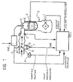
- an air inlet duct of an internal combustion engine E with spark ignition is indicated A. Air coming from a filter (not shown) passes through this duct to the engine E, in the direction of the arrows shown.
- the duct A includes a throttle valve indicated B.
- Two by-pass ducts indicated C and D extend between the regions upstream and downstream of the throttle valve B.
- a regulating screw S is provided, in known manner, in the bypass duct C.
- the rate of flow of the air through the by-pass duct D is controlled by a solenoid valve F.
- An engine speed sensor for example of the phonic wheel type, is indicated 1.
- a sensor, indicated 2 for sensing the air pressure in the duct A is provided downstream of the by-pass duct D.
- An electrical sensor for sensing the temperature of the engine E and a sensor for sensing the position of the throttle valve B are indicated 3 and 4.
- the latter may, for example, be of the potentiometric type.
- the sensors 1 to 4 are connected to corresponding inputs of an electronic control unit generally indicated ECU in Figure 1.
- This unit has a first output which controls the solenoid valve F and a second output which is connected to the input of an ignition-advance control device, indicated IAC.
- the unit ECU regulates the idling speed of the engine E by modifying the duty-cycle of the control signal PWM for the solenoid valve F and by supplying the control device IAC with a signal for correcting the advance.
- the solenoid valve F is able to exert a sensible effect on the quantity of air supplied to the engine E within quite a wide range of engine speeds, for example, within a band of approximately 2,500 revolutions per minute.
- a variation in the duty-cycle of the control signal for the solenoid valve cannot however, produce immediate results because of intrinsic delays due, for example, to the voumetric capacity of the inlet manifold and because of delays introduced by the intake and compression phases.
- the two main quantities which are measured in the engine E for the purposes of closing the control loop are the instantaneous speed of the engine and the absolute pressure in the inlet manifold.
- the unit ECU also acts on the basis of auxiliary signals supplied thereto by the temperature sensor 3 and by the position sensor 4 associated with the throttle valve B.
- the temperature sensor 3 serves the unit ECU for the selection from its memory of the correct reference values for the engine speed, the inlet manifold pressure and the reference values for the duty-cycle of the solenoid valve F and the ignition advance.
- the information provided by the position sensor 4, however, indicates whether the engine is idling and thus serves, in the final analysis, to cause the intervention or the de-activation of the idling-speed control.
- control system is based on a mathematical model of the engine which will now be described with reference to Figure 2.
- a first, fundamental decision which must be made is whether to use a "black-box" type model or a model based on physical operating principles of the engine.
- a mathematical model based on the physical operating principles of the engine permits the use of state variables which have immediate physical significance. It is thus possible to refine the model while it is being established and, if necessary, to correct it progressively so as to take account more and more thoroughly of aspects of the engine's operation.
- the mathematical model adopted in the system according to the invention is a second-order model.
- the band width of the model adopted is approximately 1Hz. This means that the impulsive components of the engine speed and of the absolute pressure in the inlet manifold are not detected and the division of the combustion cycle into the intake, compression, expansion and exhaust stages does not therefore appear in the model, nor is the fact that the engine is a multi-cylinder system taken into consideration. It is therefore assumed that the system has a continuous mode of operation.
- the range of variation of the idling speed of the engine is quite limited compared with the overall range of variability of the engine speed.
- the speed whilst during idling the speed may vary between, for example, 700 and 1,100 revolutions per minute, the absolute range of variation of the speed may, for example, be between 700 and 7,000 revolutions per minute.
- the model adopted is expressed in terms of incremental variables.
- the values of the quantities expressed in the model do not represent the total, absolute values of the variables, but the variations in those variables relative to respective reference values.
- the engine is shown schematically while idling in four functional blocks indicated BL1, BL2, BL3 and BL4.
- the block BL1 represents the electromagnetic actuator piloted by the control unit ECU, that is, the solenoid valve F of Figure 1.
- the block BL2 represents the inlet manifold A of the engine.
- the block BL3 takes account of phenomena connected with the combustion chamber.
- the block BL4 takes account of the moving mechanical parts of the engine.
- the block BL1 in fact comprises a gain block K1 which receives a variable duty-cycle (PWM) signal indicated VAE at its input.
- PWM variable duty-cycle
- the output of the block K1 represents the air flow admitted to the inlet manifold.
- the gain K1 is thus the relationship between the air flow and the duty-cycle of the solenoid valve F.
- the block BL2 includes an adder 10 which receives the output of the block K1 and the output of a gain block K3 with positive and negative signs respectively.
- This latter block takes account of the pumping action of the pistons in the cylinders and receives at its input the rate of revolution (RPM) of the engine from the block BL4.
- the output of the adder 10 is fed to an integrator 11.
- the quantity, indicated MAP, output by the integrator is the absolute pressure in the inlet manifold of the engine.
- a block K2 is interposed between the output of the integrator 11 and an input of the adder 10 which has a negative sign and takes account of the delay introduced by the filling of the capacity of the system.
- the gain K2 is inversely proportional to the volume of the inlet manifold.
- the block BL3 includes a gain block K4 whose input is connected to the output of BL2.
- the block K4 takes account of the relationship between the pressure MAP in the manifold A and the torque produced.
- the block BL3 includes an adder 13 to which are fed the ignition advance signal ADV, through a gain block K6, and the output of a gain block K5, whose input is supplied with the engine speed signal (RPM).
- This latter block takes account of the variations in the volumetric efficiency of the engine with variations in its speed.
- the quantity output by the block BL3 is a torque and this is fed, with a positive sign, to the input of an adder 14 in the block BL4 which receives, with negative signs, a signal indicative of the load torque and the output of a gain block K7, which represents the coefficient of viscous friction.
- the output of the adder 14 is fed to the input of an integrator 16 with a transfer characteristic of 1/Js, where J represents the moment of inertia of the engine and s represents the Laplace variable.
- respective predefined reference values RPM0 and MAP0 are subtracted at 21 and 22 from the current speed RPM and absolute pressure MAP in the inlet manifold.
- the difference or error values ERPM and EMAP speed and pressure are thus available at the outputs of the blocks 21 and 22.
- the integral of the speed error ERPM is indicated IRPM and is available at the output of an integration operator 23 whose input is connected to the output of the adder 21.
- the integrator 23 compensates for the static variations in the engine speed caused by loads which exert a continuous braking action such as, for example, an electric fan.
- a gain matrix Kc is produced and, in the embodiment shown, has dimensions of 2 x 4.
- the matrix contains the values of gain coefficients, which are calculated beforehand in the manner which will be described below, and correlates the variations in the quantity of air to be supplied to the engine and the variations in the advance with the instantaneous values assumed by the state variables IRPM, ERPM, EMAP and SDER.
- the reference values VAEO, ADVO, RPMO and MAPO conveniently are tabulated in memory devices of the unit ECU as functions of the engine temperature detected by the sensor 3 of Figure 1.
- the output of the differential operator 26 and the output ⁇ ADV of the matrix Kc are connected to the input of a state observer SO.
- the state variable SDER output by the state observer SO thus represents the internal state of the differentiator 26.
- a performance index is used, which is defined as follows:
- I represents a quadratic cost index constituted by the integral with time of the square of the deviations of the states and of the input quantities from their nominal values, which are zero since, in the case of the present model, incremental variables are adopted. This index is therefore a positive quantity which must be minimised.
- Q and R represent positive diagonal matrices which determine the weights of the individual components of x and u in the formation of the index I.
- the matrix Kc depends on the model adopted for the engine (by means of the matrices A and B) and also depends on the weights assigned to x and u (by means of the matrices Q and R). In other words, the matrix Kc takes account of the dynamic behaviour of the engine and of the control objectives fixed by the designer.
- the diagonal matrices Q and R have dimensions of 4x4 and 2x2 respectively. In order to calculate Kc, it is therefore necessary to assign six weight coefficients.
- This figure shows the changes in the engine speed error as a function of time expressed in seconds on the abscissa.
- control algorithm described above was implemented with an electronic control unit formed with a 16-bit microprocessor.
Landscapes
- Engineering & Computer Science (AREA)
- Chemical & Material Sciences (AREA)
- Combustion & Propulsion (AREA)
- Mechanical Engineering (AREA)
- General Engineering & Computer Science (AREA)
- Computer Hardware Design (AREA)
- Microelectronics & Electronic Packaging (AREA)
- Electrical Control Of Air Or Fuel Supplied To Internal-Combustion Engine (AREA)
- Combined Controls Of Internal Combustion Engines (AREA)
- Electrical Control Of Ignition Timing (AREA)
Claims (6)
- Verfahren für die Rückkopplungsregelung der Leerlaufdrehzahl einer Verbrennungskraftmaschine (E), der beim Betrieb über eine Leitung (A) mit einem Drosselventil (B) Luft zugeführt wird, wobei das Verfahren folgende Schritte umfaßt:a) Erfassen der Drehzahl (RPM) des Motors (E) und des Luftdruckes (MAP) der Leitung (A) des Motors (E);b) Berechnen der Differenz oder der Fehlerabweichung (ERPM) zwischen der festgestellten Motordrehzahl (RPM) und einer vorgegebenen "Ziel-Drehzahl "(RPMO) sowie der Differenz oder der Fehlerabweichung (EMAP) zwischen dem festgestellten Luftdruck (MAP) und einem vorgegebenen Referenzdruck (MAPO);c) Berechnen des Integrals (IRPM) des Motordrehzahlfehlers (ERPM);d) Auswählen der Koeffizientenwerte aus einer vorberechneten Matrix von Verstärkungskoeffizienten (Kc), welche den augenblicklichen, aus vier vorgegebenen und auf den Zustand des Motors bezogenen Variablen angenommenen Werten entsprechen;wobei die Matrix (Kc) die Änderungen (ΔVAE) der dem Motor zuzuführenden Luftmenge und die Änderungen (ΔADV) der Zündungsvorverstellung zu den augenblicklichen Werten in Beziehung setzt, die aus dem Drehzahlfehler (ERPM), dem Integral dieses Fehlers (IRPM), dem Luftdruckfehler (EMAP) und einer weiteren Zustandsvariablen (SDER) abgeleitet sind, die sich auf den internen Zustand eines Differentialoperators (26) beziehen, der auf den Wert der Zündungsvorverstellungsänderung (ΔADV) einwirkt;
wobei die Werte der Koeffizienten der Verstärkungsmatrix (Kc) zuvor auf der Basis eines linearen Systems von Gleichungen vierter Ordnung berechnet werden, welche in Übereinstimmung mit den Merkmalen eines vorgegebenen linearen mathematischen Modells (Fig. 2) des Motors (E) die zuvor genannten Zustandsvariablen (ERPM, IRPM, EMAP, SDER) mit der dem Motor zugeführten Luftmenge (VAE) und mit der Zündungsvorverstellung (ADV) funktional in Beziehung setzen, und auf der Basis der Berechnung eines zuvor als Funktion (x) der Zustandsvariablen vordefinierten Leistungsdexes (I), der dem Motor zugeführten Luftmenge (VAE) und der Zündungsvorverstellung (ADV);e) Differenzieren des Wertes (ΔADV) der Zündungsvorverstellungsänderung, welcher den Werten der aus der Matrix (Kc) ausgewählten Verstärkungskoeffizienten entspricht, mittels des genannten Differentialoperators (26); undf) Bestimmen der dem Motor zuzuführenden Luftmenge (VAE) und der dem Motor vorzugebenden Zündungsvorverstellung (ADV) in Abhängigkeit von dem vom Differentialoperator (26) gelieferten Wert und von den aus der Verstärkungsmatrix (Kc) ausgewählten Koeffizienten. - Verfahren nach Anspruch 1, dadurch gekennzeichnet, daß die vorgegebenen Werte der Drehzahl (RPMO) und des Luftdruckes (MAPO) in der Leitung entsprechend vordefinierten Funktionen der Temperatur des Motors (E) veränderlich sind.
- Verfahren nach Anspruch 1 oder Anspruch 2, dadurch gekennzeichnet, daß die dem Motor zurückzuführende Luftmenge und die dem Motor vorzugebende Zündungsvorverstellung als inkrementale Werte relativ zu vordefinierten Referenzwerten (VAEO, ADVO) bestimmt werden, die entsprechend zuvor aufgestellten Funktionen der Temperatur des Motors (E) veränderlich sind.
- System zur Rückkopplungsregelung der Leerlaufdrehzahl einer Verbrennungskraftmaschine (E), der im Betrieb Luft durch eine Leitung (A) mit einem Drosselventil (B) zugeführt wird, wobei das System in einer Kombination folgendes umfaßt:- einen elektrisch gesteuerten Verstellantrieb (F) in einer Leitung (D), die das Drosselventil (B) zum Regulieren der dem Motor (E) zugeführten Luft umgeht;- Sensormittel (1, 2) zum Liefern von für die Drehzahl (RPM) des Motors (E) und den Luftdruck (MAP) in der Einlaßleitung (A) des Motors (E) bezeichnenden elektrischen Signalen;- eine elektronische Steuereinheit (ECU), die mit dem Stellantrieb (F), den Sensormitteln (1, 2) und mit Mitteln (IAC) zum Steuern der Zündungsvorverstellung des Motors (E) verbunden ist, wobei die Einheit ausgelegt ist:wobei die Matrix (Kc) die Änderungen (ΔVAE) der dem Motor zuzuführenden Luftmenge und die Änderungen (ΔADV) der Zündungsvorverstellung zu den augenblicklichen Werten in Beziehung setzt, die aus dem Drehzahlfehler (ERPM), dem Integral dieses Fehlers (IRPM), dem Luftdruckfehler (EMAP) und einer weiteren Zustandsvariablen (SDER) abgeleitet sind, die sich auf den internen Zustand eines Differentialoperators (26) bezieht, der auf den Wert der Zündungsvorverstellungsänderung (ΔADV) einwirkt;a) zum Erfassen der Drehzahl (RPM) des Motors (E) und des Luftdruckes (MAP) in der Leitung (A) des Motors (E);b) zum Berechnen der Differenz oder der Fehlerabweichung (ERPM) zwischen der erfaßten Motordrehzahl (RPM) und einer vorgegebenen Solldrehzahl (RPMO) sowie der Differenz oder der Fehlerabweichung (EMAP) zwischen dem erfaßten Luftdruck (MAP) und einem vorgegebenen Referenzdruck (MAPO);c) zum Berechnen des Integrals (IRPM) des Motordrehzahlfehlers (ERPM);d) zum Auswählen der Koeffizientenwerte aus einer vorberechneten Matrix von Verstärkungskoeffizienten (Kc), welche den augenblicklichen, aus vier vorgegebenen und auf den Zustand des Motors bezogenen Variablen (ERPM, IRPM, EMAP, SDER) angenommenen Werten entsprechen;
wobei die Werte der Koeffizienten der Verstärkungsmatrix (Kc) zuvor auf der Basis eines linearen Systems von Gleichungen vierter Ordnung berechnet werden, welche in Übereinstimmung mit den Merkmalen eines vorgegebenen linearen mathematischen Modells (Fig. 2) des Motors (E) die zuvor genannten Zustandsvariablen (ERPM, IRPM, EMAP, SDER) mit der dem Motor zugeführten Luftmenge (VAE) und mit der Zündungsvorverstellung (ADv) funktional in Beziehung setzen, und auf der Basis der Berechnung eines zuvor als Funktion (x) der Zustandsvariablen vordefinierten Leistungsindexes (I), der dem Motor zugeführten Luftmenge (vAE) und der Zündungsvorverstellung (ADV);e) zum Differenzieren des Wertes (ΔADV) der Zündungsvorverstellungsänderung, welcher den Werten der aus der Matrix (Kc) ausgewählten verstärkungskoeffizienten entspricht, mittels des Differentialoperators (26); undf) zum Ansteuern des elektrisch gesteuerten Stellantriebes (F) und der Mittel (IAC) zum Steuern der Zündungsvorverstellung in Abhängigkeit von dem vom Differentialoperator (26) gelieferten Wert und von den aus der Verstärkungsmatrix (Kc) ausgewählten Koeffizienten. - System nach Anspruch 4, dadurch gekennzeichnet, daß die vorgegebenen Werte der Drehzahl (RPMO) und des Luftdruckes (MAPO) in der Leitung entsprechend vordefinierten Funktionen der Temperatur des Motors (E) veränderlich sind.
- System nach Anspruch 4 oder Anspruch 5, dadurch gekennzeichnet, daß die Werte für die dem Motor zuzuführende Luftmenge und für die dem Motor vorzugebende Zündungsvorverstellung als inkrementale Werte relativ zu vordefinierten Referenzwerten (VAEO, ADVO) bestimmt werden, welche entsprechend zuvor eingestellten Funktionen der Temperatur des Motors (E) veränderlich sind.
Applications Claiming Priority (2)
| Application Number | Priority Date | Filing Date | Title |
|---|---|---|---|
| IT6733390 | 1990-05-07 | ||
| IT67333A IT1241215B (it) | 1990-05-07 | 1990-05-07 | Procedimento ed apparato per il controllo della velocita' di rotazione al minimo di un motore a combustione interna. |
Publications (2)
| Publication Number | Publication Date |
|---|---|
| EP0456616A1 EP0456616A1 (de) | 1991-11-13 |
| EP0456616B1 true EP0456616B1 (de) | 1993-06-16 |
Family
ID=11301532
Family Applications (1)
| Application Number | Title | Priority Date | Filing Date |
|---|---|---|---|
| EP91830162A Expired - Lifetime EP0456616B1 (de) | 1990-05-07 | 1991-04-23 | Methode und Ausrüstung zur Steuerung der Leerlaufdrehzahl einer Innenbrennkraftmaschine |
Country Status (5)
| Country | Link |
|---|---|
| US (1) | US5121726A (de) |
| EP (1) | EP0456616B1 (de) |
| DE (1) | DE69100125T2 (de) |
| ES (1) | ES2041555T3 (de) |
| IT (1) | IT1241215B (de) |
Families Citing this family (10)
| Publication number | Priority date | Publication date | Assignee | Title |
|---|---|---|---|---|
| DE3932763C1 (de) * | 1989-09-30 | 1990-08-02 | Robert Bosch Gmbh, 7000 Stuttgart, De | |
| EP0518289B1 (de) * | 1991-06-10 | 1994-12-14 | Nippondenso Co., Ltd. | Vorrichtung zur Regelung der Drehzahl einer Brennkraftmaschine |
| US5463993A (en) * | 1994-02-28 | 1995-11-07 | General Motors Corporation | Engine speed control |
| JPH1150937A (ja) * | 1997-07-31 | 1999-02-23 | Sanshin Ind Co Ltd | 船外機用エンジンにおける暖機制御方法及び装置 |
| FR2779768B1 (fr) * | 1998-06-11 | 2000-08-18 | Renault | Procede et dispositif de regulation du fonctionnement d'un moteur a combustion interne lors d'un retour en regime de ralenti |
| US6178373B1 (en) * | 1999-04-12 | 2001-01-23 | Ford Motor Company | Engine control method using real-time engine system model |
| DE102004041660B3 (de) * | 2004-08-27 | 2006-05-04 | Siemens Ag | Verfahren und Vorrichtung zur Ermittlung eines Ausgabedrehmoments |
| US8103431B2 (en) * | 2008-01-23 | 2012-01-24 | GM Global Technology Operations LLC | Engine vacuum enhancement in an internal combustion engine |
| DE102012003581B3 (de) * | 2012-02-27 | 2013-07-18 | Iav Gmbh Ingenieurgesellschaft Auto Und Verkehr | Leerlaufregler und Verfahren zum Betrieb von Brennkraftmaschinen |
| CN111810309B (zh) * | 2020-06-23 | 2022-11-01 | 哈尔滨工程大学 | 一种基于闭环观测器的高压共轨系统喷油量预测方法 |
Family Cites Families (7)
| Publication number | Priority date | Publication date | Assignee | Title |
|---|---|---|---|---|
| JPS5951150A (ja) * | 1982-09-16 | 1984-03-24 | Nissan Motor Co Ltd | 内燃機関のアイドル回転速度制御方法 |
| JPH0697003B2 (ja) * | 1984-12-19 | 1994-11-30 | 日本電装株式会社 | 内燃機関の運転状態制御装置 |
| JPH0612093B2 (ja) * | 1985-02-19 | 1994-02-16 | 日本電装株式会社 | 内燃機関制御装置 |
| IT1185801B (it) * | 1985-06-11 | 1987-11-18 | Weber Spa | Sistema di controllo automatico del regime di rotazione minimo di un motore endotermico |
| US4785780A (en) * | 1986-07-08 | 1988-11-22 | Nippondenso Co., Ltd. | Control apparatus |
| JPS63219857A (ja) * | 1987-03-09 | 1988-09-13 | Mitsubishi Electric Corp | エンジン回転速度制御方法 |
| JPH081146B2 (ja) * | 1987-04-21 | 1996-01-10 | トヨタ自動車株式会社 | 内燃機関の非線形フイ−ドバツク制御装置 |
-
1990
- 1990-05-07 IT IT67333A patent/IT1241215B/it active IP Right Grant
-
1991
- 1991-04-23 DE DE91830162T patent/DE69100125T2/de not_active Expired - Fee Related
- 1991-04-23 EP EP91830162A patent/EP0456616B1/de not_active Expired - Lifetime
- 1991-04-23 ES ES199191830162T patent/ES2041555T3/es not_active Expired - Lifetime
- 1991-05-07 US US07/696,797 patent/US5121726A/en not_active Expired - Fee Related
Also Published As
| Publication number | Publication date |
|---|---|
| ES2041555T3 (es) | 1993-11-16 |
| IT9067333A0 (it) | 1990-05-07 |
| EP0456616A1 (de) | 1991-11-13 |
| DE69100125D1 (de) | 1993-07-22 |
| IT1241215B (it) | 1993-12-29 |
| IT9067333A1 (it) | 1991-11-07 |
| DE69100125T2 (de) | 1993-09-30 |
| US5121726A (en) | 1992-06-16 |
Similar Documents
| Publication | Publication Date | Title |
|---|---|---|
| US5282449A (en) | Method and system for engine control | |
| KR930002080B1 (ko) | 내연기관의 아이들회전수 제어장치 | |
| EP0185552B1 (de) | Vorrichtung zum Steuern des Betriebs eines Innenverbrennungsmotors | |
| EP0337366B1 (de) | Verfahren und Vorrichtung zur nichtlinearen Regelung eines Innenverbrennungsmotors | |
| US5270935A (en) | Engine with prediction/estimation air flow determination | |
| EP0728926B1 (de) | Einrichtung zur Steuerung des Luft-Kraftstoffverhältnisses in einer Brennkraftmaschine | |
| US6065449A (en) | Fuel injection control device for an internal combustion engine | |
| EP0582085A2 (de) | Brennstoffdosierungsteuersystem und Verfahren zum Schätzen des Zylinderluftstroms in Verbrennungsmotoren | |
| JP2890586B2 (ja) | 内燃機関の回転数制御装置 | |
| EP0456616B1 (de) | Methode und Ausrüstung zur Steuerung der Leerlaufdrehzahl einer Innenbrennkraftmaschine | |
| US5190020A (en) | Automatic control system for IC engine fuel injection | |
| US4860707A (en) | Non-linear feedback controller for internal combustion engine | |
| JP2512787B2 (ja) | 内燃機関のスロットル開度制御装置 | |
| US5421302A (en) | Engine speed control state prediction | |
| US5720258A (en) | Internal combustion engine control | |
| US4984545A (en) | Control system for internal combustion engine | |
| US5249558A (en) | Idle speed control system for internal combustion engine | |
| JP2564806B2 (ja) | 内燃機関のフイ−ドバツク制御方法 | |
| US5638788A (en) | Automotive actuator interface | |
| Takahashi et al. | A simple engine model for idle speed control | |
| JPH04140437A (ja) | エンジンのスロットル弁制御装置 | |
| JP2564808B2 (ja) | 内燃機関の非線形フイ−ドバツク制御方法 | |
| JPS6330491B2 (de) | ||
| JPS6325177B2 (de) | ||
| JPS6328226B2 (de) |
Legal Events
| Date | Code | Title | Description |
|---|---|---|---|
| PUAI | Public reference made under article 153(3) epc to a published international application that has entered the european phase |
Free format text: ORIGINAL CODE: 0009012 |
|
| AK | Designated contracting states |
Kind code of ref document: A1 Designated state(s): DE ES FR GB SE |
|
| 17P | Request for examination filed |
Effective date: 19911130 |
|
| 17Q | First examination report despatched |
Effective date: 19920422 |
|
| GRAA | (expected) grant |
Free format text: ORIGINAL CODE: 0009210 |
|
| AK | Designated contracting states |
Kind code of ref document: B1 Designated state(s): DE ES FR GB SE |
|
| REF | Corresponds to: |
Ref document number: 69100125 Country of ref document: DE Date of ref document: 19930722 |
|
| ET | Fr: translation filed | ||
| REG | Reference to a national code |
Ref country code: ES Ref legal event code: FG2A Ref document number: 2041555 Country of ref document: ES Kind code of ref document: T3 |
|
| PLBE | No opposition filed within time limit |
Free format text: ORIGINAL CODE: 0009261 |
|
| STAA | Information on the status of an ep patent application or granted ep patent |
Free format text: STATUS: NO OPPOSITION FILED WITHIN TIME LIMIT |
|
| 26N | No opposition filed | ||
| EAL | Se: european patent in force in sweden |
Ref document number: 91830162.3 |
|
| PGFP | Annual fee paid to national office [announced via postgrant information from national office to epo] |
Ref country code: SE Payment date: 19960314 Year of fee payment: 6 |
|
| PGFP | Annual fee paid to national office [announced via postgrant information from national office to epo] |
Ref country code: ES Payment date: 19960418 Year of fee payment: 6 |
|
| PG25 | Lapsed in a contracting state [announced via postgrant information from national office to epo] |
Ref country code: SE Effective date: 19970424 Ref country code: ES Free format text: LAPSE BECAUSE OF NON-PAYMENT OF DUE FEES Effective date: 19970424 |
|
| EUG | Se: european patent has lapsed |
Ref document number: 91830162.3 |
|
| PGFP | Annual fee paid to national office [announced via postgrant information from national office to epo] |
Ref country code: GB Payment date: 19980320 Year of fee payment: 8 |
|
| PGFP | Annual fee paid to national office [announced via postgrant information from national office to epo] |
Ref country code: DE Payment date: 19980325 Year of fee payment: 8 |
|
| REG | Reference to a national code |
Ref country code: ES Ref legal event code: FD2A Effective date: 19990301 |
|
| PG25 | Lapsed in a contracting state [announced via postgrant information from national office to epo] |
Ref country code: GB Free format text: LAPSE BECAUSE OF NON-PAYMENT OF DUE FEES Effective date: 19990423 |
|
| PGFP | Annual fee paid to national office [announced via postgrant information from national office to epo] |
Ref country code: FR Payment date: 19990430 Year of fee payment: 9 |
|
| GBPC | Gb: european patent ceased through non-payment of renewal fee |
Effective date: 19990423 |
|
| PG25 | Lapsed in a contracting state [announced via postgrant information from national office to epo] |
Ref country code: DE Free format text: LAPSE BECAUSE OF NON-PAYMENT OF DUE FEES Effective date: 20000201 |
|
| PG25 | Lapsed in a contracting state [announced via postgrant information from national office to epo] |
Ref country code: FR Free format text: LAPSE BECAUSE OF NON-PAYMENT OF DUE FEES Effective date: 20001229 |
|
| REG | Reference to a national code |
Ref country code: FR Ref legal event code: ST |