EP0337574A1 - Vorrichtung zum Zusammenstellen oder Auseinandersortieren einer Bindeeinheit, bestehend aus vier Ordnermechanismen - Google Patents
Vorrichtung zum Zusammenstellen oder Auseinandersortieren einer Bindeeinheit, bestehend aus vier Ordnermechanismen Download PDFInfo
- Publication number
- EP0337574A1 EP0337574A1 EP89200916A EP89200916A EP0337574A1 EP 0337574 A1 EP0337574 A1 EP 0337574A1 EP 89200916 A EP89200916 A EP 89200916A EP 89200916 A EP89200916 A EP 89200916A EP 0337574 A1 EP0337574 A1 EP 0337574A1
- Authority
- EP
- European Patent Office
- Prior art keywords
- mechanisms
- file
- file mechanisms
- conveyor belt
- conveyor
- Prior art date
- Legal status (The legal status is an assumption and is not a legal conclusion. Google has not performed a legal analysis and makes no representation as to the accuracy of the status listed.)
- Granted
Links
- 230000007246 mechanism Effects 0.000 title claims abstract description 114
- 238000012856 packing Methods 0.000 title claims abstract description 43
- 238000011144 upstream manufacturing Methods 0.000 claims 2
- 238000010276 construction Methods 0.000 description 6
- 210000005069 ears Anatomy 0.000 description 2
- 230000005484 gravity Effects 0.000 description 1
- 210000003128 head Anatomy 0.000 description 1
- 230000007257 malfunction Effects 0.000 description 1
- 210000001331 nose Anatomy 0.000 description 1
- 210000003857 wrist joint Anatomy 0.000 description 1
Images





Classifications
-
- B—PERFORMING OPERATIONS; TRANSPORTING
- B42—BOOKBINDING; ALBUMS; FILES; SPECIAL PRINTED MATTER
- B42C—BOOKBINDING
- B42C7/00—Manufacturing bookbinding cases or covers of books or loose-leaf binders
- B42C7/002—Manufacturing loose-leaf binders, folders
Definitions
- the invention relates to a device for assembling (disassembling) a packing unit consisting of four file mechanisms.
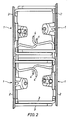
- the file mechanisms are arranged in pairs, being in line, with the ends of the operating levers projecting from the base plates directed towards each other, whilst a pair of such aligned mechanisms are moved with their bows between the bows of a further pair of aligned file mechanisms, so that the bows of the four file mechanisms assembled into a packing unit are enclosed, as it were, between the base plates of the file mechanisms.
- the assembly or disassembly of a packing unit can be effected by means of a device which is provided with a pair of receiving parts, on each of which a pair of file mechanisms, being in line, can be placed with their base plates, whilst means have been provided for pivoting the two receiving parts relative to each other between a first position for placing (removing) the file mechanisms on (from) the receiving parts and a second position, in which the file mechanisms are enclosed between the receiving parts with their bows moved between each other.
- the assembly and disassembly of the packing unit can be done quickly and efficiently by mechanic means.
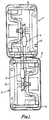
- Fig 1 illustrates a pair of file mechanisms 1 which are provided, in the usual and known manner, with a base plate 2 and a pair of bows 3 provided on said base plate 2, which bows can be opened and closed by means of an operating lever 4.
- a pair of these file mechanisms are placed in line, as illustrated in plan view in fig 1, whereby the bows of the two file mechanisms are located side by side, therefore, and the free end of an operating lever has been put through a neighbouring bow of an adjacent file mechanism and is located above the base plate 2 of said adjacent file mechanism.
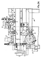
- the part of the device which is diagrammatically illustrated in plan view in Fig. 3 joins up with a device for producing the file mechanisms.
- the file mechanisms always leave the machine in question in the same position and from this machine they are supplied to the device according to the invention via a downwardly sloping chute 5.
- the file mechanisms thereby move along the chute with their longitudinal axes parallel to the longitudinal direction of the chute and all with their operating levers extending in the same direction.
- the lower end of the chute runs into one end of a conveyor belt 6 which is supported by the frame of the device and which can be driven by means of driving means (not shown), and whose upper part will move in the direction according to arrow A during operation in order to move the file mechanisms 1 in the direction according to arrow A.
- the change-over 7, 8 can be pivoted clockwise, seen in fig 3, by means of the setting cylinder 10, so that the end of the change-over 7, 8 directed towards the chute 5 will come to lie near the lower end of the chute, seen in fig 3, as a result of which the file mechanisms coming from the chute can be discharged sideways, i.e. upwards seen in fig 3.
- a pair of horizontal pins 11 and 12 are provided near the side of the conveyor belt, said pins being supported in their longitudinal direction and transversely to the longitudinal direction of the conveyor belt 6 by bushes 13 fixed in the frame.
- the pins 11 ans 12 are provided with forked heads 14 which are coupled, by means of pivot pins 15, to the ends of a lever 16 which is pivotable relative to the frame about a pin 17 extending parallel to the pins 15.
- the lever 16 in its turn is coupled to the piston rod 18 of a setting cylinder 19 which is fixed to the frame, so that the lever 16 can be pivoted to and fro by means of the setting cylinder 19.
- the pins can alternately be put in the path of movement of the file mechanisms supplied by means of the conveyor belt 6 in order to space the file mechanisms supplied in a continuous row from one another and place them one by one opposite a stamp 20 arranged near the end of the conveyor belt 6, which stamp is movable to and fro across the conveyor belt, transversely to the longitudinal direction of the conveyor belt 6, by means of a setting cylinder 21 fixed to the frame.
- a guideway 22 which extends between the side of the conveyor belt 6 and a rotary table 23 which is pivotable about a vertical axis.
- the rotary table can be pivoted through 180° about its vertical axis of rotation by means of an adjusting means 24. Furthermore a longitudinal groove 25 is provided in the upper surface of the rotary table, said groove having such dimensions that the base plate 2 of a file mechanism fits therein.
- the file mechanisms will be supplied, one by one, to the rotary table 23, such that they will come to lie with their base plate in the groove 25.
- a file mechanism present in the groove can be pushed from the rotary table 23, in the direction according to arrow B, by means of a pushing means 26 which is fixed to the end of a piston rod 27 of a setting cylinder 28 fixed to the frame.
- a feeler 28′ is fixed to the end of the piston rod 27 projecting from the setting cylinder 28 at the side remote from the pushing plate 26, said feeler being movable to and fro between a pair of adjustable stops 29 and 30 in order to determine the length of the stroke of the pushing means.
- the file mechanisms coming from the rotary table are moved in their longitudinal direction along a gravity conveyor 31 in the direction of a pair of chain conveyors 32 and 33 arranged side by side and parallel to each other.
- each chain conveyor comprises a pair of endless chains 35 guided around sprocket wheels 34, fingers 36 being fixed, regularly spaced from one another, to the links of said chain.
- sprocket wheels 38 fixed to a common shaft 37.
- a ratchet and ratchet wheel mechanism 39 provided with a lever 40, which can be pivoted to and fro by means of a setting cylinder 41 for rotating the shaft 37 in steps. It will be apparent that said stepwise rotation of the shaft 37 will also result in a stepwise movement of the chains 35 of the chain conveyors 32 and 33.
- the distance between the successive fingers 36 of the chain conveyors approximately corresponds with the width of a base plate 2 of a file mechanism.
- Two file mechanisms supplied in succession will therefore be placed in line on the conveyors 32 and 33, whereby care is taken when the machine is adjusted that the two co-axial file mechanisms in question take the position illustrated in fig 1 relative to each other.
- a pair of pushing means 42 which are fixed to the ends of piston rods 43, which form part of setting cylinders 44. Also here the ends of the piston rods 43 projecting from the setting cylinders 44 are provided with feelers 45, which are movable between adjustable stops 46 by means of which the stroke of the pushing means 42 can be adjusted.
- the pushing means 42 When the conveyors 32 and 33 take up a position in which a group of two file mechanisms is located opposite each pushing means the pushing means 42 will be set in action in order to push the file mechanisms in question from the conveyors 32 and 33 in the direction according to arrow D.
- the pairs of file mechanisms moved in the direction according to arrow D, which are arranged relative to each other as illustrated in fig 1, are moved over a slide plate 47 towards the part of the device according to the invention illustrated in figs 6 and 7.
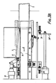
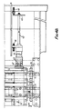
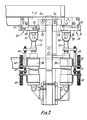
- This part comprises a pair of receiving parts 48 and 49, provided with plate-shaped parts 50, horizontally arranged in the illustrated position, to whose longitudinal edges there are fixed strips 51 having projecting noses for forming rebates 52.
- each plate 50 is large enough for receiving a group of two file mechanisms, arranged as illustrated in fig 1, on each of the receiving parts.
- ears 53 are fixed to the sides of the receiving parts directed towards each other.
- the receiving parts are pivotally coupled to the frame, near their side edges directed towards each other, by means of said ears 53 and horizontal pins 54 extending in the longitudinal direction of the receiving parts.
- each piston rod 57 there is fixed a rod 60 projecting from the cylinder and extending parallel to the piston rod, a feeler 61 being fixed to one end of said rod 60.
- the feeler 61 is movable between adjustable stops 62, by means of which the stroke of the relevant setting cylinder 58 is adjustable.
- the construction has been made such that the two receiving parts are pivotable through 90° about the axes 54 by means of the setting cylinders 58, in the direction according to arrow E and F respectively.
- the bows of the file mechanisms supported by the receiving parts will automatically be moved between one another, so that then the file mechanisms supported in pairs by the receiving parts 48 and 49 will have been put in the position illustrated in fig 2 relative to each other.
- a pushing means 63 which is fixed to the end of a piston rod 65 forming part of a setting cylinder 64, is arranged near the receiving means 48 and 49 for pushing the packing unit which has been formed away from its position between said receiving parts 48 and 49 which are pivoted towards each other. It will be apparent that by moving the pushing means from its position illustrated in fig 6 to the left the unit which has been formed and which is present between the receiving parts can be pushed out in order to be delivered to a table 65, which is arranged at the side of the receiving means remote from the setting cylinder 64.
- the packing units consisting of four file mechanisms thus supplied to the table can be moved in the direction according to arrow G by means of a pusher stamp 67 which is movable to and fro across the table 65 by means of a setting cylinder 66.
- the packing units gradually move toward the end of the table thereby.
- a desired number of packing units e.g. four or five
- a further pusher stamp 68 which is movable to and fro by means of a setting cylinder 69
- such an assembly of a desired number of packing units can be moved in the direction according to arrow H toward a take off table 70.
- the packing units may then be transferred to e.g. a box or a container for transport. Said transfer of the packing units may be done by hand or automatically, e.g. by means of magnetizable pick up plates or the like.
- Several layers, each consisting of a desired number of packing units may be stacked in the box or the container thereby.
- the packing units may be lifted from a container and be deposited on a table 71, e.g. in layers, by means of a electromagnetic pick up plate or the like.
- the packing units can then be moved in the direction according to arrow K by means of a pushing means (not shown), so that always one row or packing units lying side by side will come to lie on the upper part of a conveyor belt 72 moving in the direction according to arrow L.
- This conveyor belt places the packing unit in front of a pushing means 73, which pushes always one packing unit between a pair of receiving parts 74 and 75 corresponding with the receiving parts 48 and 49, which receiving parts 74 and 75 take up the position pivoted towards each other when a packing unit is being pushed between the receiving parts.
- each receiving part again supports one pair of file mechanisms which take up a position relative to each other as illustrated in fig 1.
- said file mechanisms are moved on the upper part of a conveyor belt 77 by means of further pushing means 76, said upper part moving in the direction according to arrow M.
- the mechanisms are placed opposite the pushing means 78 in the manner illustrated in fig 8, by means of which pushing means 78 the file mechanisms are moved on the rotary tables 79 corresponding with the rotary tables 23, and are moved from said rotary tables on the upper part of a conveyor belt 80 moving in the direction according to arrow N.
- the file mechanisms will alternately be pivoted through 180° by means of the rotary tables 79 thereby, so that all mechanisms present on the conveyor belt 80 take the same position.
- the mechanisms are supplied to a device (not shown), by means of which the mechanisms will be mounted in the files and be fixed therein.
- Fig 9 illustrates a variant to the construction according to fig 8.
- the left-hand row seen in this figure, of the mechanisms supplied on the conveyor belt 77 is carried further than the right-hand row.
- the mechanisms of the right-hand row are thereby moved directly onto the conveyor belt 80, whilst the mechanisms of the left-hand row are supplied to rotary tables 79 in order to be pivoted through 180° prior to being supplied to the conveyor belt 80.
- the mechanisms can be handled at a greater speed than with the embodiment according to fig 8.
- the file mechanisms are supplied to rotary tables 81 from the receiving parts 74 and 75.
- the file mechanisms supplied to the rotary tables are pivoted through 180° or supplied directly to a conveyor belt 82 moving to and fro, in order to be moved on the conveyor belt 80 from there.
Landscapes
- Engineering & Computer Science (AREA)
- Manufacturing & Machinery (AREA)
- Mechanical Engineering (AREA)
- Control And Other Processes For Unpacking Of Materials (AREA)
- Specific Conveyance Elements (AREA)
- Automatic Assembly (AREA)
- Auxiliary Devices For And Details Of Packaging Control (AREA)
Priority Applications (1)
| Application Number | Priority Date | Filing Date | Title |
|---|---|---|---|
| AT89200916T ATE82909T1 (de) | 1988-04-14 | 1989-04-12 | Vorrichtung zum zusammenstellen oder auseinandersortieren einer bindeeinheit, bestehend aus vier ordnermechanismen. |
Applications Claiming Priority (2)
| Application Number | Priority Date | Filing Date | Title |
|---|---|---|---|
| NL8800967A NL8800967A (nl) | 1988-04-14 | 1988-04-14 | Inrichting voor het samenstellen (uiteennemen) van een uit vier ordnermechanieken bestaande verpakkingseenheid. |
| NL8800967 | 1988-04-14 |
Publications (2)
| Publication Number | Publication Date |
|---|---|
| EP0337574A1 true EP0337574A1 (de) | 1989-10-18 |
| EP0337574B1 EP0337574B1 (de) | 1992-12-02 |
Family
ID=19852129
Family Applications (1)
| Application Number | Title | Priority Date | Filing Date |
|---|---|---|---|
| EP89200916A Expired - Lifetime EP0337574B1 (de) | 1988-04-14 | 1989-04-12 | Vorrichtung zum Zusammenstellen oder Auseinandersortieren einer Bindeeinheit, bestehend aus vier Ordnermechanismen |
Country Status (7)
| Country | Link |
|---|---|
| EP (1) | EP0337574B1 (de) |
| AT (1) | ATE82909T1 (de) |
| DE (1) | DE68903663T2 (de) |
| DK (1) | DK167965B1 (de) |
| ES (1) | ES2037390T3 (de) |
| GR (1) | GR3007123T3 (de) |
| NL (1) | NL8800967A (de) |
Cited By (2)
| Publication number | Priority date | Publication date | Assignee | Title |
|---|---|---|---|---|
| EP0696519A1 (de) * | 1994-08-11 | 1996-02-14 | Karl Bene & Co. Fabrik für Bürobedarf GmbH | Verfahren und Vorrichtungen zum Versorgen einer Ordner-Fertigungsstrasse mit Ordnermechaniken |
| EP0803378A1 (de) * | 1996-04-25 | 1997-10-29 | ELBA-Bürosysteme Erich Kraut GmbH & Co. | Vorrichtung zum Zusammenlegen und Auseinanderlegen von ineinanderlegbaren Gegenständen |
Citations (1)
| Publication number | Priority date | Publication date | Assignee | Title |
|---|---|---|---|---|
| DE1301012B (de) * | 1966-11-19 | 1969-08-14 | Fraenkisches Dachziegel Und Dr | Anordnung zum Entnehmen getrockneter Dachziegel aus Elevatoren, Niederlaessen, Speichergeruesten od. dgl. zum Stapeln und zum Setzen auf Brennwagen |
-
1988
- 1988-04-14 NL NL8800967A patent/NL8800967A/nl not_active Application Discontinuation
-
1989
- 1989-04-12 AT AT89200916T patent/ATE82909T1/de not_active IP Right Cessation
- 1989-04-12 DE DE8989200916T patent/DE68903663T2/de not_active Expired - Fee Related
- 1989-04-12 DK DK176889A patent/DK167965B1/da not_active IP Right Cessation
- 1989-04-12 EP EP89200916A patent/EP0337574B1/de not_active Expired - Lifetime
- 1989-04-12 ES ES198989200916T patent/ES2037390T3/es not_active Expired - Lifetime
-
1993
- 1993-02-23 GR GR920402735T patent/GR3007123T3/el unknown
Patent Citations (1)
| Publication number | Priority date | Publication date | Assignee | Title |
|---|---|---|---|---|
| DE1301012B (de) * | 1966-11-19 | 1969-08-14 | Fraenkisches Dachziegel Und Dr | Anordnung zum Entnehmen getrockneter Dachziegel aus Elevatoren, Niederlaessen, Speichergeruesten od. dgl. zum Stapeln und zum Setzen auf Brennwagen |
Cited By (2)
| Publication number | Priority date | Publication date | Assignee | Title |
|---|---|---|---|---|
| EP0696519A1 (de) * | 1994-08-11 | 1996-02-14 | Karl Bene & Co. Fabrik für Bürobedarf GmbH | Verfahren und Vorrichtungen zum Versorgen einer Ordner-Fertigungsstrasse mit Ordnermechaniken |
| EP0803378A1 (de) * | 1996-04-25 | 1997-10-29 | ELBA-Bürosysteme Erich Kraut GmbH & Co. | Vorrichtung zum Zusammenlegen und Auseinanderlegen von ineinanderlegbaren Gegenständen |
Also Published As
| Publication number | Publication date |
|---|---|
| DK176889D0 (da) | 1989-04-12 |
| DE68903663T2 (de) | 1993-04-08 |
| GR3007123T3 (de) | 1993-07-30 |
| NL8800967A (nl) | 1989-11-01 |
| DE68903663D1 (de) | 1993-01-14 |
| DK167965B1 (da) | 1994-01-10 |
| EP0337574B1 (de) | 1992-12-02 |
| ATE82909T1 (de) | 1992-12-15 |
| DK176889A (da) | 1989-10-15 |
| ES2037390T3 (es) | 1993-06-16 |
Similar Documents
| Publication | Publication Date | Title |
|---|---|---|
| US4519505A (en) | Egg transfer system | |
| US4505373A (en) | Egg transfer system | |
| US4618054A (en) | Equipment for feeding packaging blanks to a packaging machine | |
| CA2058843C (en) | Load former-palletizer | |
| EP1015365B1 (de) | Platten-zuführvorrichtung | |
| US4768328A (en) | Automatic tray packer | |
| US4413462A (en) | Accumulator and stacker for sandwiched biscuits and the like | |
| CA1108100A (en) | Tray loader | |
| US7565781B2 (en) | Conveyor for feeding small objects to a blister-film loader | |
| US5865106A (en) | Sandwich cookie making machine | |
| US4264253A (en) | Method and apparatus for forming a lumber stack and placing sticks between adjacent courses in the stack | |
| US2576366A (en) | Biscuit loading mechanism for conveyers | |
| US2936557A (en) | Sandwich assembly and packaging machine | |
| CA2482282C (en) | Apparatus for stacking elongated members | |
| US3593837A (en) | Packaging machine | |
| EP0337574B1 (de) | Vorrichtung zum Zusammenstellen oder Auseinandersortieren einer Bindeeinheit, bestehend aus vier Ordnermechanismen | |
| US3275165A (en) | Transfer mechanism for small elongate articles | |
| US3297129A (en) | Apparatus for conveying chocolate bars or slabs | |
| US3056482A (en) | Bread handling apparatus | |
| US3106048A (en) | Apparatus for depanning, slicing, dispensing and packaging baked articles | |
| US4645062A (en) | Transfer apparatus for flat items | |
| US4330055A (en) | Board feeder for lumber handling systems | |
| US3402803A (en) | Article conveying, collecting and metering method and apparatus | |
| US4671401A (en) | Method of and apparatus for conveying articles | |
| US2971415A (en) | Apparatus for feeding, cutting and stacking flat stock |
Legal Events
| Date | Code | Title | Description |
|---|---|---|---|
| PUAI | Public reference made under article 153(3) epc to a published international application that has entered the european phase |
Free format text: ORIGINAL CODE: 0009012 |
|
| AK | Designated contracting states |
Kind code of ref document: A1 Designated state(s): AT BE CH DE ES FR GB GR IT LI LU NL SE |
|
| 17P | Request for examination filed |
Effective date: 19900417 |
|
| 17Q | First examination report despatched |
Effective date: 19920114 |
|
| ITF | It: translation for a ep patent filed | ||
| GRAA | (expected) grant |
Free format text: ORIGINAL CODE: 0009210 |
|
| AK | Designated contracting states |
Kind code of ref document: B1 Designated state(s): AT BE CH DE ES FR GB GR IT LI LU NL SE |
|
| REF | Corresponds to: |
Ref document number: 82909 Country of ref document: AT Date of ref document: 19921215 Kind code of ref document: T |
|
| REF | Corresponds to: |
Ref document number: 68903663 Country of ref document: DE Date of ref document: 19930114 |
|
| ET | Fr: translation filed | ||
| REG | Reference to a national code |
Ref country code: ES Ref legal event code: FG2A Ref document number: 2037390 Country of ref document: ES Kind code of ref document: T3 |
|
| REG | Reference to a national code |
Ref country code: GR Ref legal event code: FG4A Free format text: 3007123 |
|
| PLBE | No opposition filed within time limit |
Free format text: ORIGINAL CODE: 0009261 |
|
| STAA | Information on the status of an ep patent application or granted ep patent |
Free format text: STATUS: NO OPPOSITION FILED WITHIN TIME LIMIT |
|
| 26N | No opposition filed | ||
| PGFP | Annual fee paid to national office [announced via postgrant information from national office to epo] |
Ref country code: GB Payment date: 19940411 Year of fee payment: 6 Ref country code: CH Payment date: 19940411 Year of fee payment: 6 |
|
| PGFP | Annual fee paid to national office [announced via postgrant information from national office to epo] |
Ref country code: ES Payment date: 19940414 Year of fee payment: 6 |
|
| PGFP | Annual fee paid to national office [announced via postgrant information from national office to epo] |
Ref country code: SE Payment date: 19940420 Year of fee payment: 6 Ref country code: BE Payment date: 19940420 Year of fee payment: 6 |
|
| PGFP | Annual fee paid to national office [announced via postgrant information from national office to epo] |
Ref country code: GR Payment date: 19940427 Year of fee payment: 6 |
|
| PGFP | Annual fee paid to national office [announced via postgrant information from national office to epo] |
Ref country code: FR Payment date: 19940429 Year of fee payment: 6 Ref country code: AT Payment date: 19940429 Year of fee payment: 6 |
|
| PGFP | Annual fee paid to national office [announced via postgrant information from national office to epo] |
Ref country code: NL Payment date: 19940430 Year of fee payment: 6 Ref country code: LU Payment date: 19940430 Year of fee payment: 6 |
|
| PGFP | Annual fee paid to national office [announced via postgrant information from national office to epo] |
Ref country code: DE Payment date: 19940530 Year of fee payment: 6 |
|
| EPTA | Lu: last paid annual fee | ||
| EAL | Se: european patent in force in sweden |
Ref document number: 89200916.8 |
|
| PG25 | Lapsed in a contracting state [announced via postgrant information from national office to epo] |
Ref country code: LU Free format text: LAPSE BECAUSE OF NON-PAYMENT OF DUE FEES Effective date: 19950412 Ref country code: GB Effective date: 19950412 Ref country code: AT Effective date: 19950412 |
|
| PG25 | Lapsed in a contracting state [announced via postgrant information from national office to epo] |
Ref country code: SE Effective date: 19950413 |
|
| PG25 | Lapsed in a contracting state [announced via postgrant information from national office to epo] |
Ref country code: ES Free format text: LAPSE BECAUSE OF NON-PAYMENT OF DUE FEES Effective date: 19950415 |
|
| PG25 | Lapsed in a contracting state [announced via postgrant information from national office to epo] |
Ref country code: LI Effective date: 19950430 Ref country code: CH Effective date: 19950430 Ref country code: BE Effective date: 19950430 |
|
| BERE | Be: lapsed |
Owner name: EGIDIUS JANSSEN N.V. Effective date: 19950430 |
|
| PG25 | Lapsed in a contracting state [announced via postgrant information from national office to epo] |
Ref country code: GR Free format text: THE PATENT HAS BEEN ANNULLED BY A DECISION OF A NATIONAL AUTHORITY Effective date: 19951031 |
|
| PG25 | Lapsed in a contracting state [announced via postgrant information from national office to epo] |
Ref country code: NL Effective date: 19951101 |
|
| GBPC | Gb: european patent ceased through non-payment of renewal fee |
Effective date: 19950412 |
|
| REG | Reference to a national code |
Ref country code: CH Ref legal event code: PL |
|
| PG25 | Lapsed in a contracting state [announced via postgrant information from national office to epo] |
Ref country code: FR Effective date: 19951229 |
|
| REG | Reference to a national code |
Ref country code: GR Ref legal event code: MM2A Free format text: 3007123 |
|
| NLV4 | Nl: lapsed or anulled due to non-payment of the annual fee |
Effective date: 19951101 |
|
| PG25 | Lapsed in a contracting state [announced via postgrant information from national office to epo] |
Ref country code: DE Effective date: 19960103 |
|
| EUG | Se: european patent has lapsed |
Ref document number: 89200916.8 |
|
| REG | Reference to a national code |
Ref country code: FR Ref legal event code: ST |
|
| REG | Reference to a national code |
Ref country code: ES Ref legal event code: FD2A |
|
| PG25 | Lapsed in a contracting state [announced via postgrant information from national office to epo] |
Ref country code: IT Free format text: LAPSE BECAUSE OF NON-PAYMENT OF DUE FEES Effective date: 20050412 |