EP0337619A1 - Système de communication - Google Patents
Système de communication Download PDFInfo
- Publication number
- EP0337619A1 EP0337619A1 EP89302818A EP89302818A EP0337619A1 EP 0337619 A1 EP0337619 A1 EP 0337619A1 EP 89302818 A EP89302818 A EP 89302818A EP 89302818 A EP89302818 A EP 89302818A EP 0337619 A1 EP0337619 A1 EP 0337619A1
- Authority
- EP
- European Patent Office
- Prior art keywords
- information
- station
- network
- allocation
- generating
- Prior art date
- Legal status (The legal status is an assumption and is not a legal conclusion. Google has not performed a legal analysis and makes no representation as to the accuracy of the status listed.)
- Granted
Links
Images




Classifications
-
- H—ELECTRICITY
- H04—ELECTRIC COMMUNICATION TECHNIQUE
- H04J—MULTIPLEX COMMUNICATION
- H04J14/00—Optical multiplex systems
- H04J14/08—Time-division multiplex systems
-
- H—ELECTRICITY
- H04—ELECTRIC COMMUNICATION TECHNIQUE
- H04J—MULTIPLEX COMMUNICATION
- H04J14/00—Optical multiplex systems
- H04J14/02—Wavelength-division multiplex systems
- H04J14/0226—Fixed carrier allocation, e.g. according to service
-
- H—ELECTRICITY
- H04—ELECTRIC COMMUNICATION TECHNIQUE
- H04J—MULTIPLEX COMMUNICATION
- H04J14/00—Optical multiplex systems
- H04J14/02—Wavelength-division multiplex systems
- H04J14/0227—Operation, administration, maintenance or provisioning [OAMP] of WDM networks, e.g. media access, routing or wavelength allocation
- H04J14/0228—Wavelength allocation for communications one-to-all, e.g. broadcasting wavelengths
- H04J14/023—Wavelength allocation for communications one-to-all, e.g. broadcasting wavelengths in WDM passive optical networks [WDM-PON]
- H04J14/0232—Wavelength allocation for communications one-to-all, e.g. broadcasting wavelengths in WDM passive optical networks [WDM-PON] for downstream transmission
-
- H—ELECTRICITY
- H04—ELECTRIC COMMUNICATION TECHNIQUE
- H04J—MULTIPLEX COMMUNICATION
- H04J14/00—Optical multiplex systems
- H04J14/02—Wavelength-division multiplex systems
- H04J14/0227—Operation, administration, maintenance or provisioning [OAMP] of WDM networks, e.g. media access, routing or wavelength allocation
- H04J14/0241—Wavelength allocation for communications one-to-one, e.g. unicasting wavelengths
- H04J14/0242—Wavelength allocation for communications one-to-one, e.g. unicasting wavelengths in WDM-PON
- H04J14/0245—Wavelength allocation for communications one-to-one, e.g. unicasting wavelengths in WDM-PON for downstream transmission, e.g. optical line terminal [OLT] to ONU
- H04J14/0247—Sharing one wavelength for at least a group of ONUs
-
- H—ELECTRICITY
- H04—ELECTRIC COMMUNICATION TECHNIQUE
- H04J—MULTIPLEX COMMUNICATION
- H04J14/00—Optical multiplex systems
- H04J14/02—Wavelength-division multiplex systems
- H04J14/0227—Operation, administration, maintenance or provisioning [OAMP] of WDM networks, e.g. media access, routing or wavelength allocation
- H04J14/0241—Wavelength allocation for communications one-to-one, e.g. unicasting wavelengths
- H04J14/0242—Wavelength allocation for communications one-to-one, e.g. unicasting wavelengths in WDM-PON
- H04J14/0249—Wavelength allocation for communications one-to-one, e.g. unicasting wavelengths in WDM-PON for upstream transmission, e.g. ONU-to-OLT or ONU-to-ONU
- H04J14/0252—Sharing one wavelength for at least a group of ONUs, e.g. for transmissions from-ONU-to-OLT or from-ONU-to-ONU
-
- H—ELECTRICITY
- H04—ELECTRIC COMMUNICATION TECHNIQUE
- H04J—MULTIPLEX COMMUNICATION
- H04J14/00—Optical multiplex systems
- H04J14/02—Wavelength-division multiplex systems
- H04J14/0278—WDM optical network architectures
- H04J14/0282—WDM tree architectures
-
- H—ELECTRICITY
- H04—ELECTRIC COMMUNICATION TECHNIQUE
- H04J—MULTIPLEX COMMUNICATION
- H04J3/00—Time-division multiplex systems
- H04J3/02—Details
- H04J3/06—Synchronising arrangements
- H04J3/0635—Clock or time synchronisation in a network
- H04J3/0682—Clock or time synchronisation in a network by delay compensation, e.g. by compensation of propagation delay or variations thereof, by ranging
-
- H—ELECTRICITY
- H04—ELECTRIC COMMUNICATION TECHNIQUE
- H04J—MULTIPLEX COMMUNICATION
- H04J3/00—Time-division multiplex systems
- H04J3/16—Time-division multiplex systems in which the time allocation to individual channels within a transmission cycle is variable, e.g. to accommodate varying complexity of signals, to vary number of channels transmitted
- H04J3/1694—Allocation of channels in TDM/TDMA networks, e.g. distributed multiplexers
Definitions
- the invention relates to communication systems and to such systems employing a passive network, for example a passive optical network.
- a passive network for example a passive optical network.
- Such passive networks control the operation of the network at the local exchange or head end for a number of customers.
- optical fibres have the capacity to handle a range of services beyond telephony.
- coaxial cable TV networks have, in the main, been used totally separately from the telephone network. It is now becoming clear that beyond the development of the switched-star network and improved advanced optical fibre technology, there is a need for a more flexible telephony based system with additional services provided.
- the present invention is concerned with a configuration capable of producing an enhanced service capability typically on a local fibre network using passive networks employing optical splitting to reduce and share costs.
- a bidirectional broadband and telephony network controllable from the exchange or head end of the network including means at the exchange or head end for allocating time slots for information packets to travel without interference to and from a plurality of receiving stations, wherein the allocating means includes means for determing the round-trip delay between the exchange or head end and each of the receiving stations and means for adjusting the round trip delay to ensure correct spacing of the information packets during passage through the network, and includes means for interrogating stations and enforcing allocation thereto to ensure each stations minimum bandwidth requirements are fulfilled, and means for dynamically allocating spare capacity to each station for bursty services.
- FIG. 1 shows a proposed configuration for a passive optical network.
- the exchange telephony block 10 provides telephony at a rate typically 20 Mbit/s on one wavelength ( ⁇ 1) and the TV block 11 provides broadcast TV on a second wavelength ( ⁇ 2) and these pass to the local exchange end 15.
- a single mode optical fibre (16) is fanned out to a number of customers premises (30, 31) via passive optical splitters (17, 18) located at the cabinet (c) and street Distribution Point (DP) positions respectively, for example.
- An 8-way split is allowable at the cabinet and a 16-way split at the DP.
- the maximum amount of splitting is selected to be 32 to keep within the optical power budget available for broadband bit-rates in this particular configuration.
- the advantages of a passive telephony network of this kind include low maintenance costs, reduced amounts of installed fibre, low fibre count cable requirements and sharing of exchange opto-electronic devices.
- the total number of customers can be increased to 128 by using 4 feeds from the head end to the cabinet. Each feed splits 32 ways.
- the single telephony-only feed can be split over the same fibre paths to all 128 customers because of its smaller bit-rate.
- Figure 3 shows the proposed configuration capable of handling the additional facilities. Individual connections are multiplexed within these channels using ATD (Asynchronous time division) and carried using a common new wavelength for the two directions of transmission.
- ATD Asynchronous time division
- the ATD channel would be routed as shown via the service access switch 42 (also based on ATD) and used as a very flexible integrated access channel for any customer requiring a mix of broadband and narrowband services.
- terminal A of the switch 42 could handle incoming and outgoing information to/from the ATD Broadband network and terminal B will handle incoming and outgoing information from other networks.
- the ATD channels are handled by ATD block (40) using wavelength 3 and for both outgoing and incoming information which will pass via the local exchange end 15 in optical form to be handled with other broadband or narrow band services.
- This wavelength carries two channels, one for the downstream directions to the customers and one for the upstream direction from the customers end to the exchange.
- All ATD packets from the exchange end are received by all customers and the actions performed are determined by header information such that a customer will accept the packet and/or re-use the packet for upstream communication or ignore the packet.
- An ATD channel bit rate of about 150 Mbit/s shared over 32 customers produces and average capacity of about 4 Mbit/s per customer. Given that ATD dynamically assigns capacity, it is expected that customers will usually be able to obtain much higher capacities on demand (eg a high probability of least 15 Mbit/s). Also, in either form of the embodiment almost the entire capacity of the link can be utilised by a single customer during those times when other customers are idle. Thus a gross bit rate of 150 Mbit/s for the ATD channel could be suitable for a wide range of business customers having bursty data services and narrowband services to transmit. In the longer term it will also be suitable for residential customers requiring viewphone connections.
- constant bit rate or variable bit rate video codecs will be used for viewphone (the latter perhaps based on a mean bit-rate of 64 kbit/s and a peak bit rate of 384 kbit/s.
- ATD channel does not restrict the choice since it would be capable of carrying either format.
- Very large bit rate services are carried on separate wavelengths (ie on wavelength ⁇ 2). Therefore the bit rate required per customer on the ATD channel is significantly smaller than would be required if ATD carried a full range of services.
- the proposed ATD configuration lends itself to being retrofitted to the Figure 1 arrangement or to a telephony only passive optical network of the type disclosed, without replacing the entire network.
- the ATD channel is provided with its own specific wavelength for the upstream and downstream direction, and customers' equipments are fitted with a wavelength filter (20) to receive this channel.
- Customer 30 can have the capability of multiple services including ATD, telephony and broadcast TV. The customer 31 still only needs the telephony service and therefore is so restricted.
- the ATD channel carries a digital multiplex with a gross bit rate of either 150 Mbit/s or 600 Mbit/s for example.
- the ATD channel is handled at the customer's end as shown in Figure 4.
- a wavelength filter (20) is associated with each channel and at optical/electrical interfaces (45, 46) data is buffered respectively to and from the local exchange end (via the distribution point and cabinet).
- Block 47 described in more detail in Figure 5 will contain a phased-locked loop, locked to the ATD transmission from the local exchange end, and used to control the frequency of transmission in the upstream direction. Additionally, each block 47 will contain an elastic buffer. The local exchange end adjusts the size of the buffer so that there is an equal number of bits in each round-trip path (exchange end to any customer and back). Suitable signals to control the size of the elastic buffers are sent over the ATD channel to access control (47) from the local exchange end.
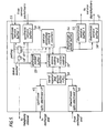
- the configuration of Figure 4 is shown in more detail in Figure 5.
- the wavelength filters 20 of Figure 4 cooperate with the downstream and upstream opto-electronic interfaces 46,45.
- the electrical output of interface 46 is received by register/buffer block 50.
- the output of block 50 is available to interface 45.
- the block 50 also contains the phase locked loop locked to the ATD transmission from the local exchange end.
- the elastic buffer within block 50 ensures correct adjustment of the round trip delay.
- Control block 52 connected to block 50 will control upstream access as well as downstream control.
- the downstream buffer 54 handles received packets passed via control 52 and the data is passed to the appropriate service buffers 57,58.
- Buffer 57 may handle viewphone or voice information and buffer 58 may deal with bursty data for example.
- the received packets are then available for conversion in standard depacketisers for receipt by the customer as voice or other data. Viewphone or data for transmission back to the exchange end for example would be received (after conversion in to digital form as necessary and packetised) by buffers 55 and 59.
- Buffer 55 could handle viewphone or voice services for example and buffer 59 could handle other data. Data from these buffers can be made available for transmission dependent on polling block 49 which will operate under the control of allocation control 56.
- This polling and allocation will depend on the priority given to services associated with buffers 55 and 59 and the allocation allowance provided from the 'd' counters within block 56.
- additional information concerning packet arrivals in buffers 55 and 59 is detected in monitoring block 48 and sent via the telephony channel (as represented by the broken line in Figure 5 from queue monitoring block 48).
- the packet information made available from buffers 61 and 62 passed to upstream packet buffer 53 to control 52 which will add information to the header to indicate 'd' allocation requirements (as described in more detail below) and thence to register/buffer 50 to interface 45 to pass along the optical medium to the exchange end.
- the local exchange end transmits a continuous series of ATD cells, which may be full or empty.
- ATD cells ATD cells
- each customer's equipment will extract cell synchronisation from either specially recognisable synchronisation cells injected regularly by the local exchange end, or from recognising the known information content and header content of empty cells.
- each cell will begin with sufficient bits so that the receiver can re-synchronise to any change of phase.
- a suitable line code eg coded mark inversion (CMI) will be used in both directions of transmission.
- the cell size is around 36 octets, with a format as described below. The same cell size is used for upstream and downstream transmissions.
- the downstream ATD block at the exchange end is shown in more detail in Figure 6.
- the information from the service access switch 42 is received by packet buffer 60.
- Customer identification is taken care of by connection number translator 61.
- the assembly block 67 assembles the packet in the format required to meet cell size and synchronising field requirements and this is made available to the customer via the opto-electronic interface 74.
- Ranging control 70 can also have access to assembler 67 to determine and set round-trip delay.
- the ranging parameters can be set via a man-machine interface for example.
- the connection number translator 64 detects incoming ranging control cells and passes this to block 70 to facilitate measurement of round trip delay. Ranging control can then if required send out further control cells via blocks 67 and 74 to the customer end to adjust the size of the elastic buffer within block 50 to ensure the round trip delay is identical with other customers. Additionally translator 64 holds connection number information identifying customers.
- Assembler 68 provides the access and control field information respectfully to accompanying the packet information to identify customers and also identify the type of information being sent (eg ranging indication or normal data). Controller 66 has the stored 'd' value applicable to the amount of access available and extracts information from the headers of packets received from the customers via blocks 73 and 63 to determine the latest 'd' allocation requirements.
- the controller 66 is shown in more detail in Figure 7.
- the change allocation control 76 receives the change allocation header subfield (as described below) from upstream packet buffer 63.
- Current 'd' values are stored for all customers in store 79.
- This is connected to poller 71 to allow loading of current 'd' values to the poller or to receive from the poller 71 a request for all current 'd' values.
- the poller 71 also provides a message to block 76 to reset rates or to initiate confirmation of the latest received "change allocation" information from a customer.
- Registers 78 have information on each customer concerning requests, modification or checks on any customer 'd' value. The latest allocation requests for all customers are held in store 77.
- packet buffer 63 This buffer provides an output to the service access switch 42.
- the buffer 63 also is accessed by the translator 64 which translates customers connection numbers.
- Polling block 17 may make use of 'd' allocation information provided on the ATD channels and (in one embodiment) use the telephony channel (as represented by the broken lines) for polling customers who have indicated that packets are waiting.
- the telephony channel of Figure 2 showed 17 subframe periods with a ranging capability within a single 2ms frame and Figure 8 is structured so that each customer has access to separate parts of the subframe (in this example subframe part 1) to enable both telephony and ATD users access to the telephony and ATD users to access to the telephony channel (in one of the embodiments).
- the configuration is of 70 sectors each of 32 bits for ATD control or telephony plus 18 bits spare to give the 2258 channels of size 1 bit.
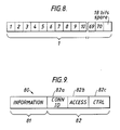
- the two multiple-user ATD channels on wavelength ⁇ 3 will typically have the cell format shown in Figure 8.
- Each packet 80 will be carried in the time slot structure in the system in either direction and will include an information field portion 81 and a header portion 82.
- the header is provided with three sub-fields 82a - 82c relating to the sub-fields of CONTROL, ACCESS, and CONNECTION ID respectively.
- the 'ACCESS' sub-field 82b contains customer address information, to be used to control transmissions in the upstream direction.
- customer address information As the downstream ATD cells are sent from the local exchange end, each with a specific setting of the ACCESS field provided by block 68 of Figure 6, a customer's equipment with matching address has the right to transmit one ATD cell in the upstream direction.
- the address value is set by the local exchange end based on information received about active terminals as described below. Thus this sub-field determines which customer is allowed to transmit next.
- the Connector I.D. (CONN ID) 82a sub-field of the header contains a connection number (typically 16 bits) which is examined by the receiving circuitary of each customer's equipment (ie block 52) to determine whether the downstream cells should be kept or discarded. There is additionally a requirement to include some bits for label error detection/correction (e.g. 4-8 bits). Thus the CONN ID sub-field determines which customer receives a downstream cell.
- the information field 81 has a size typically around 32 octets.
- a suitable method of downstream mulitplexing can employ a time slot configuration described in European Patent Publication 0168265 for example, where 'd' packages can be assigned to users to prevent monopolising the network.
- the control (CTRL) sub-field 82c of the header contains the following control information: - full/empty indication. - reset/transmit indication. - broadcasting indication. - ranging indication. - priority indication. - change allocation.
- the local exchange end equipment can measure the round-trip delay to any customer and back.
- Such measurement periods are initiated by the local exchange end sending specially recognised 'ranging' cells, with the upstream ACCESS field (upstream right to transmit) set to the customer to be measured.
- a continuous train of such cells are sent from block 70 of Figure 6 from the exchange end throughout the measurement period. This mode of operation is required so that the local exchange end can adjust the delay in the round trip path to ensure that upstream cells from different customers are correctly interleaved.
- ranging is considered to be only occasionally required and may be intiated via a man-machine interface as described above in relation to Figure 6.
- the telephone channel is used to provide the local exchange with information about active terminals.
- control of upstream polling is via two mechanisms: - information from this telephony channel on packet arrivals - polling 'recently' active users for their whole 'd' value.
- each multiservice customer is assigned 70 bits per frame. This is further subdivided into 64 bits which are set according to packet arrivals, and a further 6 bits indicating the sum of all packet arrivals in the last frame period.
- the 70 bits are dispersed regularly throughout the frame such that any adjacent group of 32 bits on this channel carries 1 bit from each of the broadband customers. If an ATD cell arrives for upstream transmission on a customer's equipment, this is indicated to the local exchange end by setting one bit, i.e. that customer's next assigned bit in the current frame. Further packet arrivals will be likewise indicated. In this way, the local exchange end receives updated information about waiting cells on each customer's equipment approximately every 1.5 microseconds (apart from the ranging period of the telephony channel).
- the upstream multiplexing is controlled from the local exchange and based on two mechanisms. - polling on each customer' control channel exactly once every 4 milliseconds - polling all active customers at least once every 125 microseconds for their permitted allocation (i.e. their 'd' value - see below)
- the polling is effected by blocks 71 and 68 of Figure 6.
- the local exchange access controller 68 regards each customer's access equipment as two devices. At the customer's end these two 'devices' are the separate responses of the access equipment to two different ACCESS addresses which it will match with.
- the first 'device' is the allocation control (Control 56 and block 52 of Figure 5) which is responsible for sending all 'change allocation' messages to the controller at the local exchange, via appropriate settings of the header. As stated above, it has a guaranteed access rate of one cell every 4 milliseconds.
- User data eg signalling information
- the header is also set to 'full'. In this case the data part is treated as belonging to the connection whose identity is given by CONN ID.
- the frequency of these transmissions from all customers' equipments may be used to provide a minimum level of monitoring of the round-trip delay so as to compute any necessary fine tuning to be conveyed to the customer's equipment.
- the second 'device' comprises the control 52 and buffer 53 and is always considered to be active by the controller at the local exchange, and is given a permitted upstream allocation - which may include zero. Changing the allocation of this device is the method by which the customer's equipment gains an appropriate upstream access rate for its queues.
- any downstream cell with either of the two matching values of ACCESS causes the next waiting cell to be transmitted upstream.
- This upstream cell will then be set to be transmitted upstream.
- This upstream cell will then be set to 'full' and the CONN ID value will be set to the appropriate connection number.
- the ACCESS field matches the control channel then the 'change allocation' part of the header is appropriately set.
- the 8 settings of the 'change allocation' field are - increase 'd' by l/ repeat increase 'd' by l - no change/ repeat no change - decrease 'd' by l/repeat decrease 'd' by l - 'd' equals zero/ repeat 'd' equals zero
- the local exchange controller (block 66) maintains 3 registers 78 for each customer, i.e. dREQ, dCHECK, and dMOD as shown in Figure 7.
- the register dREQ determines the current allocation (as described din the next section), the other two registers contain intermediate values.
- the rules governing the use of these 3 registers are set out in Table 1.
- This scheme fully corrects any isolated case of an incorrectly received control message, in either the upstream or downstream direction.
- a limited error correction field in all ATD headers eg correcting any single bit error
- the number of cases whree the allocation is incorrectly set is expected to be extremely small.
- the exchange end also operates a scheme which provides guaranteed access to each customer every 125 microseconds.
- the exchange end block 79 stores an integer value, known as 'd' value, for each customer which is the number of cells the customer requires to be guaranteed to be transmitted upstream every 125 microseconds. Every time a customer is polled by block 71 an associated counter in block 71 is decremented, starting from the value 'd'. When the counter reaches zero, the customer cannot be polled even if he has further cells waiting. Polling of that customer can only begin again after the local exchange end control block 66 via block 79 has 'reset' all counters within poller 71. In the case of the first embodiment, this condition is reached when the local exchange end has no more customers which it may validly poll (either because no more cells are waiting or all customers have exhausted their 'd' values).
- each customer is polled until his 'd' counter in poller 71 reaches zero, regardless of whether he has packets waiting. When his counter reaches zero, the customer cannot be polled until the polling of all other customers has been completed.
- the local exchange end will poll (via block 71) all customers who have been active during the last frame. Polling will contrinue to the level of each customer's 'd' value regardless of whether they have cells waiting or not. Then the local exchange end 66 will reset all its counters and block 71 begin polling again according to the same pattern.
- the local exchange end Whenever the local exchange end performs a reset of the counters, it indicates this to all customers' equipments by setting the control field of a downstream cell to indicate 'reset'. This information is used by each customer's equipment to rest different service queues of waiting cells to control the amount of cells which any one service queue can submit for upstream transmission.
- every customer is given an initial 'd' value of l, and this guarantee of access is maintained.
- a 'd' of l is equivalent to primary rate access to all 32 customers on demand.
- an idle customer will have a 'd' value of zero to prevent unnecessary polling, but every customer is guaranteed a 'd' value of l on demand (via blocks 56, 52, 50 and 45 to the exchange end blocks 73, 63 and 66), therefore no customer may increase his guaranteed access rate to a level where other customers could be refused a minimum 'd' of l.
- the controller 66 at the local exchange may receive requests from block 56 to increase a customer's 'd' value via the 'change allocation' setting. It will comply with this request provided the current level of guaranteed access is not already equal to the available capacity (ie approximately 65 cells every 125 microseconds, given a gross bit rate of around 150 Mbit/s).
- the customers equipment block 56 via block 60 will measure the number of cell arrivals, say every 4 milliseconds. If the number of arrivals exceeds the current 'd' (or part of 'd' assigned to these services) the customer's equipment as just described will signal to the local exchange end for an increase in its 'd' allocation. As already stated, the local exchange end will comply with this request if possible, but will not allow already allocated bandwidth to be used.
- change allocation information is supplied whenever the customer is next polled having first indicated that a packet is waiting via the telephony channel.
- the customers' equipment will generate a signalling call to verify its current 'd' requirements and ensure that the local exchange end remains in step with all recent changes.
- the frequency of these transmissions from all customers' equipments may be used to provide a minimum level of monitoring of the round-trip delay so as to compute any necessary fine tuning to be conveyed to the customers' equipment via the ordinary telephony channel.
- the customer's equipment sends an 'increase d' setting on its next upstream control cell.
- the local exchange end block 66 maintains both a copy of each customer's ideal requirements in the dREQ register and also holds the permitted 'd' value in another register in block 66.
- Normally 'd' is set equal to dREQ. However 'd' may be held less than dREQ until additional capacity becomes free. When this happens, any customer 'd' value which is less than its dREQ can be increased by 1 via block 76 (and no 'd' can be increased by 2 until all other such customers have received an increase of 1).
- the delay experienced by a cell will depend upon its service priority and the allocation of the total 'd' value (for a given customer) which has been assigned to its service queue.
- the delay is composed of two parts: - a round-trip delay to indicate the cell arrival to the exchange end and receive permission to transmit from the exchange end. - a random waiting period. This would be typically less than 10 microsecpnds (and would never be more than 125 microseconds for those cells requiring guaranteed access).
- the random component of delay is the only component arising in this case.
- the ATD channel is capable if carrying a wide mix of services, some bursty and some requiring guaranteed bandwidth. It may be used in an environment where there are some telephony-only customers on the original channel mixed with other customers whose services have migrated onto the ATD channel.
- the propose channels would allow the flexible use of bandwidth to carry dialogue services as they evolve.
- the migration from narrow band to broadband to the ATD situation could be effected in stages as required.
- passive network has been described in terms of optical fibre, other configurations e.g. copper cable or wire-less transmission coulld be envisaged.
- end 15 of Figure 3 has been described as the exchange end, this term is meant to encompass a location where multiple packet handling is arranged for a number of remote users (sometimes called a head end).
Landscapes
- Engineering & Computer Science (AREA)
- Computer Networks & Wireless Communication (AREA)
- Signal Processing (AREA)
- Data Exchanges In Wide-Area Networks (AREA)
- Optical Communication System (AREA)
- Interconnected Communication Systems, Intercoms, And Interphones (AREA)
- Two-Way Televisions, Distribution Of Moving Picture Or The Like (AREA)
- Pharmaceuticals Containing Other Organic And Inorganic Compounds (AREA)
- Superconductors And Manufacturing Methods Therefor (AREA)
- Small-Scale Networks (AREA)
- Eye Examination Apparatus (AREA)
Priority Applications (1)
| Application Number | Priority Date | Filing Date | Title |
|---|---|---|---|
| AT89302818T ATE95963T1 (de) | 1988-03-24 | 1989-03-21 | Kommunikationssystem. |
Applications Claiming Priority (2)
| Application Number | Priority Date | Filing Date | Title |
|---|---|---|---|
| GB888807050A GB8807050D0 (en) | 1988-03-24 | 1988-03-24 | Communication system |
| GB8807050 | 1988-03-24 |
Publications (2)
| Publication Number | Publication Date |
|---|---|
| EP0337619A1 true EP0337619A1 (fr) | 1989-10-18 |
| EP0337619B1 EP0337619B1 (fr) | 1993-10-13 |
Family
ID=10634053
Family Applications (1)
| Application Number | Title | Priority Date | Filing Date |
|---|---|---|---|
| EP89302818A Expired - Lifetime EP0337619B1 (fr) | 1988-03-24 | 1989-03-21 | Système de communication |
Country Status (11)
| Country | Link |
|---|---|
| US (1) | US5142532A (fr) |
| EP (1) | EP0337619B1 (fr) |
| JP (1) | JP3061825B2 (fr) |
| AT (1) | ATE95963T1 (fr) |
| AU (1) | AU616509B2 (fr) |
| CA (1) | CA1324204C (fr) |
| DE (1) | DE68909828T2 (fr) |
| ES (1) | ES2046466T3 (fr) |
| GB (1) | GB8807050D0 (fr) |
| HK (1) | HK135296A (fr) |
| WO (1) | WO1989009518A1 (fr) |
Cited By (20)
| Publication number | Priority date | Publication date | Assignee | Title |
|---|---|---|---|---|
| EP0425732A1 (fr) * | 1989-11-03 | 1991-05-08 | Siemens Aktiengesellschaft | Système optique passif de télécommunication |
| EP0437072A1 (fr) * | 1990-01-11 | 1991-07-17 | Stc Plc | Système de communication TDM/TDMA point à multipoint avec structure de frame par paquets |
| EP0544975A1 (fr) * | 1991-12-05 | 1993-06-09 | ALCATEL BELL Naamloze Vennootschap | Système d'attribution d'unités temporelles |
| DE4204461C1 (fr) * | 1992-02-14 | 1993-07-15 | Siemens Ag, 8000 Muenchen, De | |
| WO1993019540A1 (fr) * | 1992-03-26 | 1993-09-30 | Siemens Aktiengesellschaft | Procede de repartition d'intervalles de temps de transmission dans un reseau optique passif |
| EP0593812A1 (fr) * | 1992-10-22 | 1994-04-27 | Siemens Aktiengesellschaft | Procédé pour supprimer la dérive entre le débit de cellules d'information attendu et le débit de cellules d'information réel |
| US5519830A (en) * | 1993-06-10 | 1996-05-21 | Adc Telecommunications, Inc. | Point-to-multipoint performance monitoring and failure isolation system |
| EP0740431A1 (fr) * | 1995-04-28 | 1996-10-30 | ALCATEL BELL Naamloze Vennootschap | Procédé d'administration AMRT, station centrale, station terminale et réseau réalisant ce procédé |
| EP0691760A3 (fr) * | 1994-07-07 | 1997-09-03 | Plessey Telecomm | Multiplexage dans un réseau optique passif |
| EP0691763A3 (fr) * | 1994-07-07 | 1997-09-03 | Plessey Telecomm | Détermination de distance pour réseau de communication |
| WO1998019495A1 (fr) * | 1996-10-31 | 1998-05-07 | Robert Bosch Gmbh | Procede pour la transmission de signaux dans un reseau |
| EP0720322A3 (fr) * | 1994-12-30 | 1998-06-10 | Alcatel N.V. | Réseau d'accès optique de communication |
| EP0769226A4 (fr) * | 1995-05-02 | 1998-10-28 | Motorola Inc | Methode et systeme de gestion du spectre des frequences entre diverses applications sur un support partage |
| EP0727883A3 (fr) * | 1995-02-10 | 1999-04-14 | Kabushiki Kaisha Toshiba | Système de réseau pour communication d'information, dispositif central de contrÔle pour communication d'information et dispositif pour communication d'information utilisé dans le système, procédé de transmission d'information et procédé de modulation |
| EP0861563A4 (fr) * | 1995-11-17 | 2001-04-04 | Next Level Comm | Mecanisme d'autorisation de transmission de cellules |
| GB2380102A (en) * | 2001-09-19 | 2003-03-26 | Fujitsu Ltd | Passive optical network system |
| EP1330077A1 (fr) * | 2002-01-17 | 2003-07-23 | Samsung Electronics Co. Ltd. | Procédé pour la mise en oeuvre de plusieurs fonctions, dont une méthode d'accès, dans un système de réseau optique passif utilisant gigabit ethernet |
| EP1091525A3 (fr) * | 1999-10-07 | 2004-06-23 | Oki Electric Industry Co., Ltd. | Dispositif de station de client de communication de paquets |
| EP1657834A1 (fr) * | 2004-11-16 | 2006-05-17 | Alcatel | Terminaison de liaison d'un réseau optique avec les composants partagés et système optique passif de réseau comportant mêmes |
| US20210211836A1 (en) * | 2018-07-06 | 2021-07-08 | Apple Inc. | Ranging Priority Indication |
Families Citing this family (69)
| Publication number | Priority date | Publication date | Assignee | Title |
|---|---|---|---|---|
| US5150247A (en) * | 1989-10-30 | 1992-09-22 | Broadband Technologies, Inc. | Fiber optic telecommunication system employing continuous downlink, burst uplink transmission format with preset uplink guard band |
| US6389010B1 (en) | 1995-10-05 | 2002-05-14 | Intermec Ip Corp. | Hierarchical data collection network supporting packetized voice communications among wireless terminals and telephones |
| LU87840A1 (fr) * | 1990-05-04 | 1991-05-07 | Siemens Ag | Passives optisches telekommunikationssystem |
| US5301057A (en) * | 1990-10-15 | 1994-04-05 | Dsc Communications Corporation | Subscriber interface for a fiber optic communications terminal |
| GB9022681D0 (en) * | 1990-10-18 | 1990-11-28 | British Telecomm | Passive optical network |
| US5282202A (en) * | 1991-03-28 | 1994-01-25 | Sprint International Communications Corp. | Composite frame reconfiguration in integrated services networks |
| BE1004813A3 (nl) * | 1991-05-08 | 1993-02-02 | Bell Telephone Mfg | Optische zender/ontvangerinrichting. |
| ES2048052B1 (es) * | 1991-09-05 | 1996-01-16 | Alcatel Standard Electrica | Arquitectura para sistemas de fibra optica con acceso multiple por division en el tiempo |
| US5528283A (en) * | 1992-06-22 | 1996-06-18 | Alcatel Network Systems, Inc. | Switched video distribution apparatus |
| US5311344A (en) * | 1992-09-02 | 1994-05-10 | At&T Bell Laboratories | Bidirectional lightwave transmission system |
| US5442389A (en) * | 1992-12-28 | 1995-08-15 | At&T Corp. | Program server for interactive television system |
| NL9300281A (nl) | 1993-02-12 | 1994-09-01 | Nederland Ptt | Optisch CATV systeem. |
| US5631935A (en) * | 1993-05-06 | 1997-05-20 | Run-Rad Unlimited Networking, Ltd. | Method and apparatus for governing information transfer using an efficient transport protocol |
| US5579143A (en) * | 1993-06-04 | 1996-11-26 | Ciena Corporation | Optical system with tunable in-fiber gratings |
| US5600473A (en) * | 1993-06-04 | 1997-02-04 | Ciena Corporation | Optical amplifier systems with add/drop multiplexing |
| US5528579A (en) * | 1993-06-11 | 1996-06-18 | Adc Telecommunications, Inc. | Added bit signalling in a telecommunications system |
| US5442390A (en) * | 1993-07-07 | 1995-08-15 | Digital Equipment Corporation | Video on demand with memory accessing and or like functions |
| US5408462A (en) * | 1993-10-07 | 1995-04-18 | Adc Telecommunications, Inc. | Protection switching apparatus and method |
| US5453737A (en) * | 1993-10-08 | 1995-09-26 | Adc Telecommunications, Inc. | Control and communications apparatus |
| US5479202A (en) * | 1993-11-01 | 1995-12-26 | Gte Laboratories Incorporated | Television receiver for accessing switched broadband networks |
| EP0669748A2 (fr) * | 1994-02-28 | 1995-08-30 | US WEST Technologies, Inc. | Délivrance de service utilisant une large bande |
| US5608446A (en) * | 1994-03-31 | 1997-03-04 | Lucent Technologies Inc. | Apparatus and method for combining high bandwidth and low bandwidth data transfer |
| US5608447A (en) * | 1994-05-27 | 1997-03-04 | Bell Atlantic | Full service network |
| US5818511A (en) * | 1994-05-27 | 1998-10-06 | Bell Atlantic | Full service network |
| US5488413A (en) * | 1994-06-14 | 1996-01-30 | Xel Communications, Inc. | CATV telephony system using subsplit band for both directions of transmission |
| JPH0818514A (ja) * | 1994-06-29 | 1996-01-19 | Fujitsu Ltd | 光加入者系同一波長双方向伝送方式 |
| US6334219B1 (en) | 1994-09-26 | 2001-12-25 | Adc Telecommunications Inc. | Channel selection for a hybrid fiber coax network |
| US6189037B1 (en) * | 1994-09-30 | 2001-02-13 | Intel Corporation | Broadband data interface |
| JP3511408B2 (ja) * | 1994-10-06 | 2004-03-29 | パイオニア株式会社 | Catv電話システムの端末器及びセンタ装置 |
| DE4438942A1 (de) * | 1994-10-31 | 1996-05-02 | Sel Alcatel Ag | Optisches Nachrichtenübertragungssystem für Kabelfernsehsignale und für teilnehmerindividuelle Signale |
| US5612948A (en) * | 1994-11-18 | 1997-03-18 | Motorola, Inc. | High bandwidth communication network and method |
| US5729824A (en) * | 1994-12-09 | 1998-03-17 | Raychem Corporation | Distributed digital loop carriers system using coaxial cable |
| US5659793A (en) * | 1994-12-22 | 1997-08-19 | Bell Atlantic Video Services, Inc. | Authoring tools for multimedia application development and network delivery |
| US5826102A (en) * | 1994-12-22 | 1998-10-20 | Bell Atlantic Network Services, Inc. | Network arrangement for development delivery and presentation of multimedia applications using timelines to integrate multimedia objects and program objects |
| USRE42236E1 (en) | 1995-02-06 | 2011-03-22 | Adc Telecommunications, Inc. | Multiuse subcarriers in multipoint-to-point communication using orthogonal frequency division multiplexing |
| US7280564B1 (en) | 1995-02-06 | 2007-10-09 | Adc Telecommunications, Inc. | Synchronization techniques in multipoint-to-point communication using orthgonal frequency division multiplexing |
| KR0179979B1 (ko) | 1995-10-13 | 1999-05-01 | 김광호 | 정보텔레비젼의 문자 표시장치 |
| US5790806A (en) * | 1996-04-03 | 1998-08-04 | Scientific-Atlanta, Inc. | Cable data network architecture |
| JP3429925B2 (ja) | 1995-11-28 | 2003-07-28 | パイオニア株式会社 | Catv通信方法、catv通信システム、そのセンタ装置、及び、その端末装置 |
| DE19547110A1 (de) * | 1995-12-16 | 1997-06-19 | Sel Alcatel Ag | Mobilfunksystem mit leitungsgebundenen Teilnehmeranschlüssen |
| US6219840B1 (en) * | 1996-03-29 | 2001-04-17 | Motorola, Inc. | Method for assigning communication resources in a communication system |
| US5999970A (en) * | 1996-04-10 | 1999-12-07 | World Gate Communications, Llc | Access system and method for providing interactive access to an information source through a television distribution system |
| US20040078824A1 (en) * | 1996-04-10 | 2004-04-22 | Worldgate Communications | Access system and method for providing interactive access to an information source through a television distribution system |
| US5956338A (en) * | 1996-07-09 | 1999-09-21 | Ericsson, Inc. | Protocol for broadband data communication over a shared medium |
| US5960353A (en) * | 1996-12-24 | 1999-09-28 | Lucent Technologies, Inc. | Microcell load measurement using feedback control |
| US5999612A (en) * | 1997-05-27 | 1999-12-07 | International Business Machines Corporation | Integrated telephony and data services over cable networks |
| US6049539A (en) * | 1997-09-15 | 2000-04-11 | Worldgate Communications, Inc. | Access system and method for providing interactive access to an information source through a networked distribution system |
| US6477143B1 (en) | 1998-01-25 | 2002-11-05 | Dror Ginossar | Method and apparatus for packet network congestion avoidance and control |
| US7272298B1 (en) | 1998-05-06 | 2007-09-18 | Burst.Com, Inc. | System and method for time-shifted program viewing |
| US7558472B2 (en) | 2000-08-22 | 2009-07-07 | Tivo Inc. | Multimedia signal processing system |
| US8577205B2 (en) | 1998-07-30 | 2013-11-05 | Tivo Inc. | Digital video recording system |
| US8380041B2 (en) | 1998-07-30 | 2013-02-19 | Tivo Inc. | Transportable digital video recorder system |
| US6233389B1 (en) | 1998-07-30 | 2001-05-15 | Tivo, Inc. | Multimedia time warping system |
| US6377782B1 (en) | 1999-03-01 | 2002-04-23 | Mediacell, Inc. | Method and apparatus for communicating between a client device and a linear broadband network |
| FR2790628B1 (fr) * | 1999-03-02 | 2001-06-01 | Sextant Avionique | Reseau de distribution d'informations et procede de gestion de panne de ce reseau |
| US7103907B1 (en) * | 1999-05-11 | 2006-09-05 | Tellabs Bedford, Inc. | RF return optical transmission |
| US20030128983A1 (en) * | 1999-05-11 | 2003-07-10 | Buabbud George H. | Digital RF return over fiber |
| US6460182B1 (en) * | 1999-05-11 | 2002-10-01 | Marconi Communications, Inc. | Optical communication system for transmitting RF signals downstream and bidirectional telephony signals which also include RF control signals upstream |
| JP2001292148A (ja) * | 2000-02-01 | 2001-10-19 | Hitachi Ltd | Atm通信装置及びその帯域制御方法 |
| JP4903298B2 (ja) * | 2000-04-14 | 2012-03-28 | ウォーターフロント・テクノロジーズ エルエルシー | 通信装置、通信システム及び音声・データ統合方法 |
| US6912060B1 (en) * | 2000-07-05 | 2005-06-28 | Lexmark International, Inc. | Photoprinter control of peripheral devices |
| KR20040026177A (ko) * | 2002-09-23 | 2004-03-30 | 삼성전자주식회사 | 방송 및 통신 신호를 수용할 수 있는 광가입자망 시스템 |
| KR20040094141A (ko) * | 2003-05-02 | 2004-11-09 | (주)세종네트워크테크놀로지스 | 광섬유를 이용한 미디어 통합형 홈 게이트웨이 시스템 |
| KR100724902B1 (ko) | 2004-01-30 | 2007-06-04 | 삼성전자주식회사 | 댁내 방송서비스 수용을 위한 수동형 광가입자망에프티티에이치 시스템 |
| KR100687707B1 (ko) | 2004-02-12 | 2007-02-27 | 한국전자통신연구원 | 통신 방송 융합 액세스 시스템과 그 방법 |
| EP1813111A2 (fr) | 2004-11-19 | 2007-08-01 | Tivo, Inc. | Procede et appareil de transfert securise d'un contenu diffuse precedement |
| KR100785299B1 (ko) * | 2005-09-22 | 2007-12-17 | 삼성전자주식회사 | 방송채널정보 제공시스템 및 그 방법 |
| US10225013B2 (en) * | 2016-12-01 | 2019-03-05 | Arris Enterprises Llc | Channel management to provide narrowcast data services using visible light communication |
| US11240176B2 (en) | 2018-08-21 | 2022-02-01 | At&T Intellectual Property I, L.P. | Time-spaced messaging for facilitating network communications |
Citations (3)
| Publication number | Priority date | Publication date | Assignee | Title |
|---|---|---|---|---|
| EP0138365A2 (fr) * | 1983-09-07 | 1985-04-24 | BRITISH TELECOMMUNICATIONS public limited company | Réseau de communications comportant un seul noeud et plusieurs stations |
| EP0168265A2 (fr) * | 1984-07-13 | 1986-01-15 | BRITISH TELECOMMUNICATIONS public limited company | Systèmes de communication |
| EP0182601A1 (fr) * | 1984-11-15 | 1986-05-28 | Nec Corporation | Appareil de communication de multiplexage temporel en directions multiples |
Family Cites Families (9)
| Publication number | Priority date | Publication date | Assignee | Title |
|---|---|---|---|---|
| CA1158738A (fr) * | 1980-04-30 | 1983-12-13 | Manitoba Telephone System (The) | Module de distribution de signaux video et de donnees avec terminal d'abonne |
| GB2125653B (en) * | 1982-08-04 | 1986-08-13 | Plessey Co Plc | Improved time slot arrangements for local area network systems |
| US4633462A (en) * | 1983-07-18 | 1986-12-30 | The Board Of Trustees Of The University Of Illinois | Multiple access communication on a CATV reverse channel |
| JPS61145995A (ja) * | 1984-12-20 | 1986-07-03 | Toshiba Corp | 集線分配装置 |
| GB8525591D0 (en) * | 1985-10-17 | 1985-11-20 | British Telecomm | Communications network |
| GB8526620D0 (en) * | 1985-10-29 | 1985-12-04 | British Telecomm | Communications network |
| JPH0761183B2 (ja) * | 1986-01-09 | 1995-06-28 | 株式会社東芝 | 集線分配装置 |
| GB8618118D0 (en) * | 1986-07-24 | 1986-09-03 | British Telecomm | Communications system |
| US5043982A (en) * | 1989-05-24 | 1991-08-27 | At&T Bell Laboratories | Multichannel multipoint network using time-division multiplexing incorporating a time offset for propagation delay |
-
1988
- 1988-03-24 GB GB888807050A patent/GB8807050D0/en active Pending
-
1989
- 1989-03-21 EP EP89302818A patent/EP0337619B1/fr not_active Expired - Lifetime
- 1989-03-21 WO PCT/GB1989/000299 patent/WO1989009518A1/fr not_active Ceased
- 1989-03-21 JP JP1503790A patent/JP3061825B2/ja not_active Expired - Lifetime
- 1989-03-21 US US07/601,701 patent/US5142532A/en not_active Expired - Lifetime
- 1989-03-21 ES ES198989302818T patent/ES2046466T3/es not_active Expired - Lifetime
- 1989-03-21 AT AT89302818T patent/ATE95963T1/de not_active IP Right Cessation
- 1989-03-21 DE DE89302818T patent/DE68909828T2/de not_active Expired - Lifetime
- 1989-03-21 AU AU33643/89A patent/AU616509B2/en not_active Ceased
- 1989-03-22 CA CA000594532A patent/CA1324204C/fr not_active Expired - Lifetime
-
1996
- 1996-07-25 HK HK135296A patent/HK135296A/en not_active IP Right Cessation
Patent Citations (3)
| Publication number | Priority date | Publication date | Assignee | Title |
|---|---|---|---|---|
| EP0138365A2 (fr) * | 1983-09-07 | 1985-04-24 | BRITISH TELECOMMUNICATIONS public limited company | Réseau de communications comportant un seul noeud et plusieurs stations |
| EP0168265A2 (fr) * | 1984-07-13 | 1986-01-15 | BRITISH TELECOMMUNICATIONS public limited company | Systèmes de communication |
| EP0182601A1 (fr) * | 1984-11-15 | 1986-05-28 | Nec Corporation | Appareil de communication de multiplexage temporel en directions multiples |
Non-Patent Citations (4)
| Title |
|---|
| ELECTRONICS LETTERS, vol. 23, no. 24, 19th November 1987, pages 1255-1257, Stevenage, Herts, GB; J.R. STERN et al.: "Passive optical local networks for telephony applications and beyond" * |
| IBM TECHNICAL DISCLOSURE BULLETIN, vol. 18, no. 2, July 1975, page 484, New York, US; R.L. WEST: "Time-frame structure for TDMA communication" * |
| IEEE INTERNATIONAL CONFERENCE ON COMMUNICATIONS 1985, Chicago, Illinois, 23rd-26th June 1985, vol. 2, pages 987-993, IEEE, New York, US; S. ARENACCIO et al.: "Asynchronous techniques for burst time plan changes in the ITALSAT system" * |
| PATENT ABSTRACTS OF JAPAN, vol. 8, no. 70 (E-235)[1507], 3rd April 1984; & JP-A-58 218 250 (MITSUBISHI DENKI K.K.) 19-12-1983 * |
Cited By (29)
| Publication number | Priority date | Publication date | Assignee | Title |
|---|---|---|---|---|
| EP0425732A1 (fr) * | 1989-11-03 | 1991-05-08 | Siemens Aktiengesellschaft | Système optique passif de télécommunication |
| EP0437072A1 (fr) * | 1990-01-11 | 1991-07-17 | Stc Plc | Système de communication TDM/TDMA point à multipoint avec structure de frame par paquets |
| US5353285A (en) * | 1991-12-05 | 1994-10-04 | Alcatel N.V. | Time slot management system |
| EP0544975A1 (fr) * | 1991-12-05 | 1993-06-09 | ALCATEL BELL Naamloze Vennootschap | Système d'attribution d'unités temporelles |
| DE4204461C1 (fr) * | 1992-02-14 | 1993-07-15 | Siemens Ag, 8000 Muenchen, De | |
| WO1993019540A1 (fr) * | 1992-03-26 | 1993-09-30 | Siemens Aktiengesellschaft | Procede de repartition d'intervalles de temps de transmission dans un reseau optique passif |
| EP0565739A1 (fr) * | 1992-03-26 | 1993-10-20 | Siemens Aktiengesellschaft | Procédé d'allocation de canaux temporals dans un réseau optique passif |
| EP0593812A1 (fr) * | 1992-10-22 | 1994-04-27 | Siemens Aktiengesellschaft | Procédé pour supprimer la dérive entre le débit de cellules d'information attendu et le débit de cellules d'information réel |
| US5519830A (en) * | 1993-06-10 | 1996-05-21 | Adc Telecommunications, Inc. | Point-to-multipoint performance monitoring and failure isolation system |
| US5655068A (en) * | 1993-06-10 | 1997-08-05 | Adc Telecommunications, Inc. | Point-to-multipoint performance monitoring and failure isolation system |
| EP0691760A3 (fr) * | 1994-07-07 | 1997-09-03 | Plessey Telecomm | Multiplexage dans un réseau optique passif |
| EP0691763A3 (fr) * | 1994-07-07 | 1997-09-03 | Plessey Telecomm | Détermination de distance pour réseau de communication |
| EP0720322A3 (fr) * | 1994-12-30 | 1998-06-10 | Alcatel N.V. | Réseau d'accès optique de communication |
| EP0727883A3 (fr) * | 1995-02-10 | 1999-04-14 | Kabushiki Kaisha Toshiba | Système de réseau pour communication d'information, dispositif central de contrÔle pour communication d'information et dispositif pour communication d'information utilisé dans le système, procédé de transmission d'information et procédé de modulation |
| US5754535A (en) * | 1995-04-28 | 1998-05-19 | Alcatel N.V. | Method for TDMA management, central station, terminal station and network system to perform this method |
| EP0740431A1 (fr) * | 1995-04-28 | 1996-10-30 | ALCATEL BELL Naamloze Vennootschap | Procédé d'administration AMRT, station centrale, station terminale et réseau réalisant ce procédé |
| CN1075913C (zh) * | 1995-04-28 | 2001-12-05 | 阿尔卡塔尔有限公司 | 用于tdma管理的方法,实现这种方法的中心站,终端站及网络系统 |
| EP0769226A4 (fr) * | 1995-05-02 | 1998-10-28 | Motorola Inc | Methode et systeme de gestion du spectre des frequences entre diverses applications sur un support partage |
| EP0861563A4 (fr) * | 1995-11-17 | 2001-04-04 | Next Level Comm | Mecanisme d'autorisation de transmission de cellules |
| WO1998019495A1 (fr) * | 1996-10-31 | 1998-05-07 | Robert Bosch Gmbh | Procede pour la transmission de signaux dans un reseau |
| EP1091525A3 (fr) * | 1999-10-07 | 2004-06-23 | Oki Electric Industry Co., Ltd. | Dispositif de station de client de communication de paquets |
| GB2380102A (en) * | 2001-09-19 | 2003-03-26 | Fujitsu Ltd | Passive optical network system |
| GB2380102B (en) * | 2001-09-19 | 2003-10-15 | Fujitsu Ltd | Passive optical network system |
| EP1330077A1 (fr) * | 2002-01-17 | 2003-07-23 | Samsung Electronics Co. Ltd. | Procédé pour la mise en oeuvre de plusieurs fonctions, dont une méthode d'accès, dans un système de réseau optique passif utilisant gigabit ethernet |
| US7289439B2 (en) | 2002-01-17 | 2007-10-30 | Samsung Electronics Co., Ltd. | Method for implementing various functions in gigabit ethernet-passive optical network system and structure of ethernet frame employed in the same |
| EP1657834A1 (fr) * | 2004-11-16 | 2006-05-17 | Alcatel | Terminaison de liaison d'un réseau optique avec les composants partagés et système optique passif de réseau comportant mêmes |
| US7613395B2 (en) | 2004-11-16 | 2009-11-03 | Alcatel Lucent | Optical network termination apparatus with shared components and passive optical network system comprising same |
| US20210211836A1 (en) * | 2018-07-06 | 2021-07-08 | Apple Inc. | Ranging Priority Indication |
| US11770676B2 (en) * | 2018-07-06 | 2023-09-26 | Apple Inc. | Ranging priority indication |
Also Published As
| Publication number | Publication date |
|---|---|
| DE68909828D1 (de) | 1993-11-18 |
| GB8807050D0 (en) | 1988-04-27 |
| JP3061825B2 (ja) | 2000-07-10 |
| CA1324204C (fr) | 1993-11-09 |
| AU616509B2 (en) | 1991-10-31 |
| DE68909828T2 (de) | 1994-04-14 |
| ATE95963T1 (de) | 1993-10-15 |
| WO1989009518A1 (fr) | 1989-10-05 |
| EP0337619B1 (fr) | 1993-10-13 |
| US5142532A (en) | 1992-08-25 |
| AU3364389A (en) | 1989-10-16 |
| HK135296A (en) | 1996-08-02 |
| JPH03504308A (ja) | 1991-09-19 |
| ES2046466T3 (es) | 1994-02-01 |
Similar Documents
| Publication | Publication Date | Title |
|---|---|---|
| EP0337619B1 (fr) | Système de communication | |
| EP0961522B1 (fr) | Nouveau procédé et dispositif de mise en forme du trafic dans un système d'access à large bande, basée sûr fibre optique | |
| EP0544975B1 (fr) | Système d'attribution d'unités temporelles | |
| US5166675A (en) | Communication system carrying out polling for request and data simultaneously and in parallel | |
| EP0889611B1 (fr) | Méthode de multiplexage dans le temps et dispositif correspondant à usage dans une station centrale et terminaux de réseau de communication | |
| US6317234B1 (en) | Communications network | |
| US6697374B1 (en) | Optical network communication system | |
| JPH11505378A (ja) | 顧客家屋内装置用の多重時間スロットもどりチャンネルを有する一点対多点の広帯域サービスドロップ | |
| EP0758822A1 (fr) | Méthode et circuit pour l'allocation dynamique de bande passante dans un système de communication TDM-AMRT | |
| KR19990067471A (ko) | 패킷 흐름제어에 관한 장치 및 방법 | |
| EP0810808B1 (fr) | Dispositif pour le transport de cellules ATM | |
| KR100786527B1 (ko) | 수동광분기망에서 맥을 위한 승인 요청 방법 | |
| US6298049B1 (en) | Method and arrangement for upstream timeslot assignment, and communication system wherein the method is used | |
| Angelopoulos et al. | A TDMA based Access Control Scheme for APON's | |
| US6243364B1 (en) | Upstream access method in bidirectional telecommunication system | |
| US7272315B1 (en) | Technique for transferring information in a passive optical network | |
| KR100758784B1 (ko) | 수동광분기망의 광대역국사장치에서의 맥 스케줄링 장치및 그 방법 | |
| JP2002185542A (ja) | 通信システム | |
| US6914909B2 (en) | Method to divide upstream timeslots in a time division multiple access system, related line terminator and related network terminator | |
| JP3697312B2 (ja) | 1対多通信システムのアクセス方式 | |
| JPH07505032A (ja) | 受動的光通信網における伝送時間割り当て方法 | |
| JP2002247064A (ja) | 親局装置、子局装置及び通信システム | |
| JPH08163168A (ja) | 多重通信方式 |
Legal Events
| Date | Code | Title | Description |
|---|---|---|---|
| PUAI | Public reference made under article 153(3) epc to a published international application that has entered the european phase |
Free format text: ORIGINAL CODE: 0009012 |
|
| AK | Designated contracting states |
Kind code of ref document: A1 Designated state(s): AT BE CH DE ES FR GB GR IT LI LU NL SE |
|
| 17P | Request for examination filed |
Effective date: 19900109 |
|
| 17Q | First examination report despatched |
Effective date: 19911122 |
|
| RAP1 | Party data changed (applicant data changed or rights of an application transferred) |
Owner name: BRITISH TELECOMMUNICATIONS PUBLIC LIMITED COMPANY |
|
| GRAA | (expected) grant |
Free format text: ORIGINAL CODE: 0009210 |
|
| AK | Designated contracting states |
Kind code of ref document: B1 Designated state(s): AT BE CH DE ES FR GB GR IT LI LU NL SE |
|
| PG25 | Lapsed in a contracting state [announced via postgrant information from national office to epo] |
Ref country code: AT Effective date: 19931013 Ref country code: CH Effective date: 19931013 Ref country code: LI Effective date: 19931013 Ref country code: GR Free format text: LAPSE BECAUSE OF FAILURE TO SUBMIT A TRANSLATION OF THE DESCRIPTION OR TO PAY THE FEE WITHIN THE PRESCRIBED TIME-LIMIT Effective date: 19931013 |
|
| REF | Corresponds to: |
Ref document number: 95963 Country of ref document: AT Date of ref document: 19931015 Kind code of ref document: T |
|
| ITF | It: translation for a ep patent filed | ||
| REF | Corresponds to: |
Ref document number: 68909828 Country of ref document: DE Date of ref document: 19931118 |
|
| REG | Reference to a national code |
Ref country code: CH Ref legal event code: PL |
|
| REG | Reference to a national code |
Ref country code: ES Ref legal event code: FG2A Ref document number: 2046466 Country of ref document: ES Kind code of ref document: T3 |
|
| ET | Fr: translation filed | ||
| PG25 | Lapsed in a contracting state [announced via postgrant information from national office to epo] |
Ref country code: LU Free format text: LAPSE BECAUSE OF NON-PAYMENT OF DUE FEES Effective date: 19940331 |
|
| PLBE | No opposition filed within time limit |
Free format text: ORIGINAL CODE: 0009261 |
|
| STAA | Information on the status of an ep patent application or granted ep patent |
Free format text: STATUS: NO OPPOSITION FILED WITHIN TIME LIMIT |
|
| 26N | No opposition filed | ||
| EAL | Se: european patent in force in sweden |
Ref document number: 89302818.3 |
|
| REG | Reference to a national code |
Ref country code: GB Ref legal event code: 732E |
|
| REG | Reference to a national code |
Ref country code: GB Ref legal event code: IF02 |
|
| PGFP | Annual fee paid to national office [announced via postgrant information from national office to epo] |
Ref country code: ES Payment date: 20020307 Year of fee payment: 14 |
|
| PGFP | Annual fee paid to national office [announced via postgrant information from national office to epo] |
Ref country code: BE Payment date: 20020308 Year of fee payment: 14 |
|
| PG25 | Lapsed in a contracting state [announced via postgrant information from national office to epo] |
Ref country code: ES Free format text: LAPSE BECAUSE OF NON-PAYMENT OF DUE FEES Effective date: 20030322 |
|
| PG25 | Lapsed in a contracting state [announced via postgrant information from national office to epo] |
Ref country code: BE Free format text: LAPSE BECAUSE OF NON-PAYMENT OF DUE FEES Effective date: 20030331 |
|
| BERE | Be: lapsed |
Owner name: BRITISH *TELECOMMUNICATIONS P.L.C. Effective date: 20030331 |
|
| REG | Reference to a national code |
Ref country code: ES Ref legal event code: FD2A Effective date: 20030322 |
|
| PGFP | Annual fee paid to national office [announced via postgrant information from national office to epo] |
Ref country code: NL Payment date: 20080214 Year of fee payment: 20 Ref country code: GB Payment date: 20080228 Year of fee payment: 20 Ref country code: SE Payment date: 20080218 Year of fee payment: 20 Ref country code: IT Payment date: 20080218 Year of fee payment: 20 |
|
| PGFP | Annual fee paid to national office [announced via postgrant information from national office to epo] |
Ref country code: FR Payment date: 20080211 Year of fee payment: 20 Ref country code: DE Payment date: 20080227 Year of fee payment: 20 |
|
| REG | Reference to a national code |
Ref country code: GB Ref legal event code: PE20 Expiry date: 20090320 |
|
| PG25 | Lapsed in a contracting state [announced via postgrant information from national office to epo] |
Ref country code: NL Free format text: LAPSE BECAUSE OF EXPIRATION OF PROTECTION Effective date: 20090321 |
|
| NLV7 | Nl: ceased due to reaching the maximum lifetime of a patent |
Effective date: 20090321 |
|
| PG25 | Lapsed in a contracting state [announced via postgrant information from national office to epo] |
Ref country code: GB Free format text: LAPSE BECAUSE OF EXPIRATION OF PROTECTION Effective date: 20090320 |