EP0337763B1 - Injecteur de combustible pour moteurs à injection - Google Patents
Injecteur de combustible pour moteurs à injection Download PDFInfo
- Publication number
- EP0337763B1 EP0337763B1 EP89303617A EP89303617A EP0337763B1 EP 0337763 B1 EP0337763 B1 EP 0337763B1 EP 89303617 A EP89303617 A EP 89303617A EP 89303617 A EP89303617 A EP 89303617A EP 0337763 B1 EP0337763 B1 EP 0337763B1
- Authority
- EP
- European Patent Office
- Prior art keywords
- fuel
- fuel injection
- injector assembly
- housing
- fuel injector
- Prior art date
- Legal status (The legal status is an assumption and is not a legal conclusion. Google has not performed a legal analysis and makes no representation as to the accuracy of the status listed.)
- Expired - Lifetime
Links
- 239000000446 fuel Substances 0.000 title claims description 83
- 238000002347 injection Methods 0.000 claims description 39
- 239000007924 injection Substances 0.000 claims description 39
- 238000002485 combustion reaction Methods 0.000 claims description 8
- 239000007921 spray Substances 0.000 claims description 2
- 230000001419 dependent effect Effects 0.000 description 3
- 238000011144 upstream manufacturing Methods 0.000 description 3
- 230000004907 flux Effects 0.000 description 2
- 238000000889 atomisation Methods 0.000 description 1
- 238000010276 construction Methods 0.000 description 1
- 238000004519 manufacturing process Methods 0.000 description 1
- 230000035699 permeability Effects 0.000 description 1
- 230000001737 promoting effect Effects 0.000 description 1
- 239000000126 substance Substances 0.000 description 1
- 230000001960 triggered effect Effects 0.000 description 1
Images


Classifications
-
- F—MECHANICAL ENGINEERING; LIGHTING; HEATING; WEAPONS; BLASTING
- F02—COMBUSTION ENGINES; HOT-GAS OR COMBUSTION-PRODUCT ENGINE PLANTS
- F02M—SUPPLYING COMBUSTION ENGINES IN GENERAL WITH COMBUSTIBLE MIXTURES OR CONSTITUENTS THEREOF
- F02M61/00—Fuel-injectors not provided for in groups F02M39/00 - F02M57/00 or F02M67/00
- F02M61/04—Fuel-injectors not provided for in groups F02M39/00 - F02M57/00 or F02M67/00 having valves, e.g. having a plurality of valves in series
- F02M61/047—Fuel-injectors not provided for in groups F02M39/00 - F02M57/00 or F02M67/00 having valves, e.g. having a plurality of valves in series the valves being formed by deformable nozzle parts, e.g. flexible plates or discs with fuel discharge orifices
-
- F—MECHANICAL ENGINEERING; LIGHTING; HEATING; WEAPONS; BLASTING
- F02—COMBUSTION ENGINES; HOT-GAS OR COMBUSTION-PRODUCT ENGINE PLANTS
- F02D—CONTROLLING COMBUSTION ENGINES
- F02D41/00—Electrical control of supply of combustible mixture or its constituents
- F02D41/008—Controlling each cylinder individually
- F02D41/0087—Selective cylinder activation, i.e. partial cylinder operation
-
- F—MECHANICAL ENGINEERING; LIGHTING; HEATING; WEAPONS; BLASTING
- F02—COMBUSTION ENGINES; HOT-GAS OR COMBUSTION-PRODUCT ENGINE PLANTS
- F02M—SUPPLYING COMBUSTION ENGINES IN GENERAL WITH COMBUSTIBLE MIXTURES OR CONSTITUENTS THEREOF
- F02M35/00—Combustion-air cleaners, air intakes, intake silencers, or induction systems specially adapted for, or arranged on, internal-combustion engines
- F02M35/10—Air intakes; Induction systems
- F02M35/10209—Fluid connections to the air intake system; their arrangement of pipes, valves or the like
- F02M35/10216—Fuel injectors; Fuel pipes or rails; Fuel pumps or pressure regulators
-
- F—MECHANICAL ENGINEERING; LIGHTING; HEATING; WEAPONS; BLASTING
- F02—COMBUSTION ENGINES; HOT-GAS OR COMBUSTION-PRODUCT ENGINE PLANTS
- F02M—SUPPLYING COMBUSTION ENGINES IN GENERAL WITH COMBUSTIBLE MIXTURES OR CONSTITUENTS THEREOF
- F02M35/00—Combustion-air cleaners, air intakes, intake silencers, or induction systems specially adapted for, or arranged on, internal-combustion engines
- F02M35/10—Air intakes; Induction systems
- F02M35/104—Intake manifolds
- F02M35/108—Intake manifolds with primary and secondary intake passages
- F02M35/1085—Intake manifolds with primary and secondary intake passages the combustion chamber having multiple intake valves
-
- F—MECHANICAL ENGINEERING; LIGHTING; HEATING; WEAPONS; BLASTING
- F02—COMBUSTION ENGINES; HOT-GAS OR COMBUSTION-PRODUCT ENGINE PLANTS
- F02M—SUPPLYING COMBUSTION ENGINES IN GENERAL WITH COMBUSTIBLE MIXTURES OR CONSTITUENTS THEREOF
- F02M51/00—Fuel-injection apparatus characterised by being operated electrically
- F02M51/06—Injectors peculiar thereto with means directly operating the valve needle
- F02M51/061—Injectors peculiar thereto with means directly operating the valve needle using electromagnetic operating means
- F02M51/0614—Injectors peculiar thereto with means directly operating the valve needle using electromagnetic operating means characterised by arrangement of electromagnets or fixed armature
- F02M51/0617—Injectors peculiar thereto with means directly operating the valve needle using electromagnetic operating means characterised by arrangement of electromagnets or fixed armature having two or more electromagnets
-
- F—MECHANICAL ENGINEERING; LIGHTING; HEATING; WEAPONS; BLASTING
- F02—COMBUSTION ENGINES; HOT-GAS OR COMBUSTION-PRODUCT ENGINE PLANTS
- F02M—SUPPLYING COMBUSTION ENGINES IN GENERAL WITH COMBUSTIBLE MIXTURES OR CONSTITUENTS THEREOF
- F02M51/00—Fuel-injection apparatus characterised by being operated electrically
- F02M51/06—Injectors peculiar thereto with means directly operating the valve needle
- F02M51/061—Injectors peculiar thereto with means directly operating the valve needle using electromagnetic operating means
- F02M51/0625—Injectors peculiar thereto with means directly operating the valve needle using electromagnetic operating means characterised by arrangement of mobile armatures
- F02M51/0664—Injectors peculiar thereto with means directly operating the valve needle using electromagnetic operating means characterised by arrangement of mobile armatures having a cylindrically or partly cylindrically shaped armature, e.g. entering the winding; having a plate-shaped or undulated armature entering the winding
- F02M51/0667—Injectors peculiar thereto with means directly operating the valve needle using electromagnetic operating means characterised by arrangement of mobile armatures having a cylindrically or partly cylindrically shaped armature, e.g. entering the winding; having a plate-shaped or undulated armature entering the winding the armature acting as a valve or having a short valve body attached thereto
-
- F—MECHANICAL ENGINEERING; LIGHTING; HEATING; WEAPONS; BLASTING
- F02—COMBUSTION ENGINES; HOT-GAS OR COMBUSTION-PRODUCT ENGINE PLANTS
- F02M—SUPPLYING COMBUSTION ENGINES IN GENERAL WITH COMBUSTIBLE MIXTURES OR CONSTITUENTS THEREOF
- F02M51/00—Fuel-injection apparatus characterised by being operated electrically
- F02M51/06—Injectors peculiar thereto with means directly operating the valve needle
- F02M51/08—Injectors peculiar thereto with means directly operating the valve needle specially for low-pressure fuel-injection
-
- F—MECHANICAL ENGINEERING; LIGHTING; HEATING; WEAPONS; BLASTING
- F02—COMBUSTION ENGINES; HOT-GAS OR COMBUSTION-PRODUCT ENGINE PLANTS
- F02M—SUPPLYING COMBUSTION ENGINES IN GENERAL WITH COMBUSTIBLE MIXTURES OR CONSTITUENTS THEREOF
- F02M2200/00—Details of fuel-injection apparatus, not otherwise provided for
- F02M2200/44—Valves, e.g. injectors, with valve bodies arranged side-by-side
Definitions
- the present invention relates to a fuel injector assembly for a fuel-injected engine, which has a plurality of intake passages opening into each combustion chamber.
- Some recent high-performance engines have two intake passages independently opening into each combustion chamber and associated with respective fuel injection valves for increased charging efficiency and independent fuel control required by the intake passages.
- One known fuel injection assembly for use with such a fuel-injected engine is disclosed in Japanese Laid-Open Patent Publication No. 60-32957.
- the intake passages have respective solenoid-operated fuel injection valves disposed therein.
- One of the intake passages is opened and closed dependent on the rotational speed of the engine or the load on the engine, and at the same time fuel injection valve disposed in said one intake passage is controlled in timed relation to the opening and closing of the intake passage.
- a cylinder head or an intake manifold in which the intake passages are defined must have delivery passages defined therein for distributing fuel to the respective fuel injection valves. Therefore, the cylinder head is complex in configuration, high in cost, and has to be assembled through an increased number of steps.
- a fuel injector assembly for an internal combustion engine, such assembly comprising a housing adapted to be mounted in an intake passage of an engine which opens into a cylinder thereof, characterised by two or more electro-magnetic fuel injection valve means located in respective passageways defined in the housing, and means for providing a magnetic shield extending between the adjacent fuel injection valve means of the assembly.
- All the solenoid-operated fuel injection valve means associated with each cylinder are assembled in a single housing and placed in the corresponding intake passage. Since fuel can be supplied through a common fuel supply passage to the fuel injection valve means associated with each cylinder, the cost of manufacture of the fuel injector assembly is reduced, and the fuel injection valve means can easily be installed in place. Because the magnetic shield layer is disposed between the fuel injection valve means, even when solenoids of the fuel injection valve means are selectively energized, they are not subjected to magnetic interference and can reliably be operated.
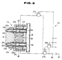
- FIGS. 1 through 3 show a fuel injector assembly according to an embodiment of the present invention.
- An intake passage 11 for introducing air is defined in the intake manifold or cylinder head of an engine (not shown) and has an inlet passage 12 and a pair of first and second branch passages 13a, 13b branched from the inlet passage 12 and opening into a combustion chamber (not shown) in an engine cylinder.
- the first and second branch passages 13a, 13b house therein respective intake valves 14a, 14b for selectively opening and closing intake ports of the first and second branch passages 13a, 13b.
- a shutter valve 15b is disposed in the first branch passage 13b for selectively opening and closing the first branch passage 13b.
- the intake valves 14a, 14b are openable and closable in synchronism with rotation of the crankshaft (not shown) of the engine through a known valve operating mechanism.
- the shutter valve 15a is openable and closable by an actuator (not shown) dependent on operating conditions of the engine in the manner disclosed in Japanese Laid-Open Patent Publication No. 60-32957 or 59-43922, for example.
- the inlet passage 12, or the upstream end of the intake passage 11, is connected to an air cleaner or the like for drawing in air.
- the intake passage 11 is provided in combination with one combustion chamber. Therefore, a four-cylinder engine has four intake passages 11 coupled respectively to the four combustion chambers.
- Two fuel injection valves 17a, 17b which are encased in a single housing 16 are disposed in the intake passage 11 just upstream of the point where the inlet passage 12 is branched into the first and second branch passages 13a, 13b.
- the housing 16 is fixed to a wall defining the intake passage 11 and has defined therein a fuel supply hole 18 and two housing holes 19a, 19b extending perpendicularly to the fuel supply hole 18.
- the fuel supply hole 18 is connected through a pipe or the like to the fuel injector assembly associated with an adjacent engine cylinder, and is coupled to a fuel pump (not shown).
- the housing holes 19a, 19b have ends directed toward the substantial centers of the branch passages 13a, 13 and opposite ends opening into the fuel supply hole 18.
- the housing holes 19a, 19b accomodate therein the respective fuel injection valves 17a, 17b which comprise springs 20a, 20b, solenoids 21a, 21b and needle valves 22a, 22b.
- the solenoids 21a, 21b are annularly fixedly positioned centrally in the respectively housing holes 19a, 19b and electrically connected to a driver circuit 23 (described later).
- the needle valves 22a, 22b have needles on their ends which are loosely fitted respectively in the end openings of the housing holes 19a, 19b, thus defining fuel injection nozzles 24a, 24b.
- the needle valves 22a, 22b also have respective tapered seats 22c, 22d near the needles and engageable with corresponding seats around the end openings of the housing holes 19a, 19b for closing the fuel injection valves 24a, 24b.
- the needle valves 22a, 22b are axially movably disposed in the housing holes 19a, 19b, respectively, and extend through the respective solenoids 21a, 21b. When the solenoids 21a, 21b are energised, the needle valves 22a, 22b are axially displaced to open the fuel injection valves 24a, 24b.
- the springs 20a, 20b act on the respective needle valves 22a, 22b for normally urging them in a direction to close the fuel injection nozzles 24a, 24b.
- the housing 16 has a vacant hole or air gap 25 having a rectangular cross section defined therein between the housing holes 19a, 19b, the vacant hole 25 serving as a magnetic shield air layer.
- the vacant hole 25 lies between the solenoids 21a, 21b and extend fully across the solenoids 21a, 21b to provide a shield against magnetic fluxes produced by the solenoids 21a, 21b.
- the vacant hole 25 is filled with air, but may be filled with a substance having a low magnetic permeability.
- the driver circuit 23 comprises a battery 26, a switching power transistor 27a connected between the battery 26 and the solenoid 21a, a power transistor 27b connected between the battery 26 and the solenoid 21b, and a transistor 28b for controlling the power transistor 27b.
- the power transistor 27b has an emitter connected to the solenoid 21b, a collector to the battery 26, and a base to the collector of the transistor 28b.
- the power transistor 27a has an emitter connected to the solenoid 21a, a collector to the battery 26, and a base to a control circuit (not shown) to which the emitter and base of the transistor 28b are also coupled.
- the control circuit produces a control signal to selectively turn on the power transistors 27a, 27b for selectively energizing the solenoids 21a, 21b of the fuel injection valves 17a, 17b to inject fuel.
- the solenoids 21a, 21b of both of the fuel injection valves 17a, 17b are energized to enable the fuel injection valves 17a, 17b to inject fuel from the nozzles 24a, 24b into the branch passages 13a, 13b.
- the fuel injector assembly can easily be installed in place, does not make the cylinder head or intake manifold complex in configuration, and can be manufactured at a low cost. It is not necessary to connect fuel supply pipes respectively to the fuel injection valves 17a, 17b because the fuel injection valves 17a, 17b share the fuel supply hole 18 defined in the housing 16.
- the cylinder head or intake manifold is therefore simple in construction and highly reliable in operation as there is no danger of fuel leakage which would otherwise be caused from separate fuel supply pipes.
- FIGS. 4 and 5 show a fuel injector assembly according to another embodiment of the present invention. Those parts shown in FIGS. 4 and 5 which are identical to those in FIGS. 1 through 3 are denoted by identical reference numerals.
- a housing 16 additionally defines therein an auxiliary air passage 29 connected to a region upstream of a throttle valve (not shown), and an auxiliary air injection hole 30 extending from the auxiliary air passage 29 and opening toward one of the branch passages 13a.
- a driver circuit 23 energizes the solenoid 21a of the fuel injection valve 17a at all times, and energizes the solenoid 21b on the fuel injection valve 17b with the transistor 28b and the power transistor 27b based on a control signal from the control circuit.
Landscapes
- Engineering & Computer Science (AREA)
- Chemical & Material Sciences (AREA)
- Combustion & Propulsion (AREA)
- Mechanical Engineering (AREA)
- General Engineering & Computer Science (AREA)
- Physics & Mathematics (AREA)
- Electromagnetism (AREA)
- Fuel-Injection Apparatus (AREA)
Claims (5)
Applications Claiming Priority (2)
| Application Number | Priority Date | Filing Date | Title |
|---|---|---|---|
| JP89726/88 | 1988-04-12 | ||
| JP63089726A JP2537263B2 (ja) | 1988-04-12 | 1988-04-12 | 燃料噴射式エンジンの吸気装置 |
Publications (2)
| Publication Number | Publication Date |
|---|---|
| EP0337763A1 EP0337763A1 (fr) | 1989-10-18 |
| EP0337763B1 true EP0337763B1 (fr) | 1992-08-05 |
Family
ID=13978768
Family Applications (1)
| Application Number | Title | Priority Date | Filing Date |
|---|---|---|---|
| EP89303617A Expired - Lifetime EP0337763B1 (fr) | 1988-04-12 | 1989-04-12 | Injecteur de combustible pour moteurs à injection |
Country Status (5)
| Country | Link |
|---|---|
| US (1) | US4955347A (fr) |
| EP (1) | EP0337763B1 (fr) |
| JP (1) | JP2537263B2 (fr) |
| CA (1) | CA1327297C (fr) |
| DE (1) | DE68902346T2 (fr) |
Families Citing this family (19)
| Publication number | Priority date | Publication date | Assignee | Title |
|---|---|---|---|---|
| GB2227281B (en) * | 1989-01-19 | 1993-03-10 | Ilmor Engineering Limited | Fuel injection assembly for internal combustion engine |
| JPH03279623A (ja) * | 1990-03-27 | 1991-12-10 | Mazda Motor Corp | 多弁式エンジンの制御装置 |
| JPH04128567A (ja) * | 1990-09-20 | 1992-04-30 | Mazda Motor Corp | エンジンの吸気装置 |
| CA2050452A1 (fr) * | 1990-11-19 | 1992-05-20 | John C. Hickey | Ensemble injecteur de carburant moule par injection |
| JP2887797B2 (ja) * | 1991-02-15 | 1999-04-26 | ヤマハ発動機株式会社 | 4サイクルエンジンの吸気装置 |
| JP3631770B2 (ja) * | 1993-01-22 | 2005-03-23 | 本田技研工業株式会社 | 内燃機関の吸気装置 |
| DE4307368A1 (de) * | 1993-03-09 | 1994-09-15 | Porsche Ag | Zylinderkopf für eine Brennkraftmaschine |
| US5447140A (en) * | 1993-12-20 | 1995-09-05 | General Motors Corporation | Fuel injection |
| DE4403148C2 (de) * | 1994-02-03 | 1999-01-28 | Iav Motor Gmbh | Elektromagnetisch ansteuerbares Mehrstrahleinspritzventil, insbesondere für Verbrennungsmotoren mit zwei Ansaugkanälen pro Zylinder |
| US5551401A (en) * | 1994-05-31 | 1996-09-03 | Suzuki Motor Corporation | Air suction system for internal combustion engine |
| JPH0821341A (ja) * | 1994-07-01 | 1996-01-23 | Yamaha Motor Co Ltd | 内燃機関の燃料供給装置 |
| FR2722538B1 (fr) * | 1994-07-12 | 1996-09-20 | Magneti Marelli France | Injecteur de carburant "bi-jet" a noyaux et entrefers en parallele pour moteur a combustion interne alimente par injection |
| FR2722541B1 (fr) * | 1994-07-12 | 1996-09-20 | Magneti Marelli France Sa | Injecteur de carburant "bi-jet" a aassistance pneumatique de pulverisation, pour moteur a combustioninterne alimente par injection |
| DE10034446A1 (de) * | 2000-07-15 | 2002-01-24 | Bosch Gmbh Robert | Brennstoffeinspritzventil |
| JP4110920B2 (ja) | 2002-10-25 | 2008-07-02 | トヨタ自動車株式会社 | 電磁駆動弁装置 |
| FI119030B (fi) * | 2005-04-28 | 2008-06-30 | Waertsilae Finland Oy | Polttomoottorin polttoaineen syöttölaitteiston ohjausjärjestelmä |
| DE102008044244A1 (de) | 2008-12-01 | 2010-06-02 | Robert Bosch Gmbh | Brennkraftmaschine |
| CN105484833B (zh) * | 2014-09-19 | 2019-05-17 | 浙江福爱电子有限公司 | 一种液体喷射计量单元 |
| CN106168149A (zh) * | 2015-05-22 | 2016-11-30 | 浙江福爱电子有限公司 | 一种机动车 |
Family Cites Families (13)
| Publication number | Priority date | Publication date | Assignee | Title |
|---|---|---|---|---|
| DE2412490A1 (de) * | 1974-03-15 | 1975-09-25 | Kunz Dieter | Einspritz- und vernebelungskopf |
| US4149496A (en) * | 1977-12-21 | 1979-04-17 | General Motors Corporation | Throttle body injection apparatus |
| US4508091A (en) * | 1979-10-26 | 1985-04-02 | Colt Industries Operating Corp | Fuel metering apparatus with multi-stage fuel metering valve assembly |
| JPS5770914A (en) * | 1980-10-20 | 1982-05-01 | Yamaha Motor Co Ltd | Air intake controller for multi-valvetype internal combustionn engine |
| US4347823A (en) * | 1981-02-24 | 1982-09-07 | General Motors Corporation | Throttle body injection apparatus with distribution skirt |
| US4465050A (en) * | 1981-05-19 | 1984-08-14 | Nippon Soken, Inc. | Device for atomizing the fuel for an internal-combustion engine |
| JPS5828475A (ja) * | 1981-08-10 | 1983-02-19 | 長坂 平吉 | 動力ハンマ− |
| JPS59131969U (ja) * | 1983-02-24 | 1984-09-04 | 日産自動車株式会社 | 燃料噴射装置 |
| JPH0799131B2 (ja) * | 1984-11-09 | 1995-10-25 | マツダ株式会社 | 燃料噴射式エンジンの吸気装置 |
| JPS61152770U (fr) * | 1985-03-14 | 1986-09-20 | ||
| JPS62203971A (ja) * | 1986-02-28 | 1987-09-08 | Fuji Heavy Ind Ltd | 内燃機関の燃料噴射装置 |
| US4708117A (en) * | 1986-04-14 | 1987-11-24 | Colt Industries Inc. | Multi-point fuel injection apparatus |
| JPS6361737A (ja) * | 1986-09-01 | 1988-03-17 | Hitachi Ltd | 燃料制御装置 |
-
1988
- 1988-04-12 JP JP63089726A patent/JP2537263B2/ja not_active Expired - Lifetime
-
1989
- 1989-04-12 DE DE8989303617T patent/DE68902346T2/de not_active Expired - Lifetime
- 1989-04-12 CA CA000596442A patent/CA1327297C/fr not_active Expired - Fee Related
- 1989-04-12 EP EP89303617A patent/EP0337763B1/fr not_active Expired - Lifetime
- 1989-04-12 US US07/337,012 patent/US4955347A/en not_active Expired - Fee Related
Also Published As
| Publication number | Publication date |
|---|---|
| JP2537263B2 (ja) | 1996-09-25 |
| US4955347A (en) | 1990-09-11 |
| DE68902346D1 (de) | 1992-09-10 |
| EP0337763A1 (fr) | 1989-10-18 |
| JPH01262361A (ja) | 1989-10-19 |
| DE68902346T2 (de) | 1992-12-10 |
| CA1327297C (fr) | 1994-03-01 |
Similar Documents
| Publication | Publication Date | Title |
|---|---|---|
| EP0337763B1 (fr) | Injecteur de combustible pour moteurs à injection | |
| KR950004962B1 (ko) | 엔진의 흡기장치 | |
| EP0985819B1 (fr) | Agencement de pompe à carburant et de soupape RGE dans un moteur à injection directe de carburant | |
| JP2500028B2 (ja) | 吸気ポ―ト圧力制御装置及びエンジン制御方法 | |
| US6634333B2 (en) | Direct injection type internal combustion engine | |
| ES2025054B3 (es) | Aparato para inyeccion de fuel para motores de combustion interna. | |
| EP0321313A3 (fr) | Moteur à combustion interne pour véhicule | |
| GB1115562A (en) | An improved fuel injection system for internal combustion engines | |
| EP0654123B1 (fr) | Injecteur de carburant entourant une tige de soupape d'admission | |
| BR8804298A (pt) | Valvula de injecao de combustivel eletromagneticamente comandada para motores de combustao interna | |
| US4408587A (en) | Fuel injection system | |
| ES2065168T3 (es) | Inyector de combustible para motores de combustion interna. | |
| JP3303619B2 (ja) | 内燃機関の燃料供給装置 | |
| JPS6145332Y2 (fr) | ||
| KR950013210B1 (ko) | 내연기관의 연료분사장치 | |
| GB2321085A (en) | Secondary air intake valve for a port-throttled i.c. engine | |
| KR200149885Y1 (ko) | 엔진의 연료 분사장치 | |
| JPH048295Y2 (fr) | ||
| JPS61232382A (ja) | エンジンの吸気装置 | |
| JPH0693941A (ja) | 内燃機関の燃料供給装置 | |
| JPH0245029B2 (fr) | ||
| JPS62203971A (ja) | 内燃機関の燃料噴射装置 | |
| JPS61237881A (ja) | エンジンの吸気装置 | |
| JPH0631586B2 (ja) | 多吸気弁式内燃機関の燃料噴射装置 | |
| JPH04365969A (ja) | エンジンの吸気装置 |
Legal Events
| Date | Code | Title | Description |
|---|---|---|---|
| PUAI | Public reference made under article 153(3) epc to a published international application that has entered the european phase |
Free format text: ORIGINAL CODE: 0009012 |
|
| AK | Designated contracting states |
Kind code of ref document: A1 Designated state(s): DE FR GB |
|
| 17P | Request for examination filed |
Effective date: 19891109 |
|
| 17Q | First examination report despatched |
Effective date: 19910322 |
|
| GRAA | (expected) grant |
Free format text: ORIGINAL CODE: 0009210 |
|
| AK | Designated contracting states |
Kind code of ref document: B1 Designated state(s): DE FR GB |
|
| PG25 | Lapsed in a contracting state [announced via postgrant information from national office to epo] |
Ref country code: FR Effective date: 19920805 |
|
| REF | Corresponds to: |
Ref document number: 68902346 Country of ref document: DE Date of ref document: 19920910 |
|
| EN | Fr: translation not filed | ||
| PLBE | No opposition filed within time limit |
Free format text: ORIGINAL CODE: 0009261 |
|
| STAA | Information on the status of an ep patent application or granted ep patent |
Free format text: STATUS: NO OPPOSITION FILED WITHIN TIME LIMIT |
|
| 26N | No opposition filed | ||
| PGFP | Annual fee paid to national office [announced via postgrant information from national office to epo] |
Ref country code: FR Payment date: 19950411 Year of fee payment: 7 |
|
| PGFP | Annual fee paid to national office [announced via postgrant information from national office to epo] |
Ref country code: GB Payment date: 19960403 Year of fee payment: 8 |
|
| PGFP | Annual fee paid to national office [announced via postgrant information from national office to epo] |
Ref country code: DE Payment date: 19960418 Year of fee payment: 8 |
|
| PG25 | Lapsed in a contracting state [announced via postgrant information from national office to epo] |
Ref country code: GB Effective date: 19970412 |
|
| GBPC | Gb: european patent ceased through non-payment of renewal fee |
Effective date: 19970412 |
|
| PG25 | Lapsed in a contracting state [announced via postgrant information from national office to epo] |
Ref country code: DE Free format text: LAPSE BECAUSE OF NON-PAYMENT OF DUE FEES Effective date: 19980101 |