EP0337787B1 - Luftreifen - Google Patents
Luftreifen Download PDFInfo
- Publication number
- EP0337787B1 EP0337787B1 EP89303690A EP89303690A EP0337787B1 EP 0337787 B1 EP0337787 B1 EP 0337787B1 EP 89303690 A EP89303690 A EP 89303690A EP 89303690 A EP89303690 A EP 89303690A EP 0337787 B1 EP0337787 B1 EP 0337787B1
- Authority
- EP
- European Patent Office
- Prior art keywords
- rubber layer
- foam
- rubber
- tread
- pneumatic tire
- Prior art date
- Legal status (The legal status is an assumption and is not a legal conclusion. Google has not performed a legal analysis and makes no representation as to the accuracy of the status listed.)
- Expired - Lifetime
Links
Images



Classifications
-
- B—PERFORMING OPERATIONS; TRANSPORTING
- B60—VEHICLES IN GENERAL
- B60C—VEHICLE TYRES; TYRE INFLATION; TYRE CHANGING; CONNECTING VALVES TO INFLATABLE ELASTIC BODIES IN GENERAL; DEVICES OR ARRANGEMENTS RELATED TO TYRES
- B60C1/00—Tyres characterised by the chemical composition or the physical arrangement or mixture of the composition
-
- B—PERFORMING OPERATIONS; TRANSPORTING
- B60—VEHICLES IN GENERAL
- B60C—VEHICLE TYRES; TYRE INFLATION; TYRE CHANGING; CONNECTING VALVES TO INFLATABLE ELASTIC BODIES IN GENERAL; DEVICES OR ARRANGEMENTS RELATED TO TYRES
- B60C11/00—Tyre tread bands; Tread patterns; Anti-skid inserts
- B60C11/14—Anti-skid inserts, e.g. vulcanised into the tread band
- B60C11/18—Anti-skid inserts, e.g. vulcanised into the tread band of strip form, e.g. metallic combs, rubber strips of different wear resistance
-
- B—PERFORMING OPERATIONS; TRANSPORTING
- B60—VEHICLES IN GENERAL
- B60C—VEHICLE TYRES; TYRE INFLATION; TYRE CHANGING; CONNECTING VALVES TO INFLATABLE ELASTIC BODIES IN GENERAL; DEVICES OR ARRANGEMENTS RELATED TO TYRES
- B60C1/00—Tyres characterised by the chemical composition or the physical arrangement or mixture of the composition
- B60C1/0016—Compositions of the tread
-
- B—PERFORMING OPERATIONS; TRANSPORTING
- B60—VEHICLES IN GENERAL
- B60C—VEHICLE TYRES; TYRE INFLATION; TYRE CHANGING; CONNECTING VALVES TO INFLATABLE ELASTIC BODIES IN GENERAL; DEVICES OR ARRANGEMENTS RELATED TO TYRES
- B60C11/00—Tyre tread bands; Tread patterns; Anti-skid inserts
-
- B—PERFORMING OPERATIONS; TRANSPORTING
- B60—VEHICLES IN GENERAL
- B60C—VEHICLE TYRES; TYRE INFLATION; TYRE CHANGING; CONNECTING VALVES TO INFLATABLE ELASTIC BODIES IN GENERAL; DEVICES OR ARRANGEMENTS RELATED TO TYRES
- B60C11/00—Tyre tread bands; Tread patterns; Anti-skid inserts
- B60C11/0041—Tyre tread bands; Tread patterns; Anti-skid inserts comprising different tread rubber layers
- B60C11/005—Tyre tread bands; Tread patterns; Anti-skid inserts comprising different tread rubber layers with cap and base layers
-
- B—PERFORMING OPERATIONS; TRANSPORTING
- B60—VEHICLES IN GENERAL
- B60C—VEHICLE TYRES; TYRE INFLATION; TYRE CHANGING; CONNECTING VALVES TO INFLATABLE ELASTIC BODIES IN GENERAL; DEVICES OR ARRANGEMENTS RELATED TO TYRES
- B60C11/00—Tyre tread bands; Tread patterns; Anti-skid inserts
- B60C11/0041—Tyre tread bands; Tread patterns; Anti-skid inserts comprising different tread rubber layers
- B60C11/005—Tyre tread bands; Tread patterns; Anti-skid inserts comprising different tread rubber layers with cap and base layers
- B60C11/0058—Tyre tread bands; Tread patterns; Anti-skid inserts comprising different tread rubber layers with cap and base layers with different cap rubber layers in the axial direction
-
- B—PERFORMING OPERATIONS; TRANSPORTING
- B60—VEHICLES IN GENERAL
- B60C—VEHICLE TYRES; TYRE INFLATION; TYRE CHANGING; CONNECTING VALVES TO INFLATABLE ELASTIC BODIES IN GENERAL; DEVICES OR ARRANGEMENTS RELATED TO TYRES
- B60C11/00—Tyre tread bands; Tread patterns; Anti-skid inserts
- B60C11/14—Anti-skid inserts, e.g. vulcanised into the tread band
- B60C2011/147—Foamed rubber or sponge rubber on the tread band
Definitions
- the present invention relates to a pneumatic tire, and more specifically to a pneumatic tire having good wear resistance in summer (including spring and autumn) without deteriorating steerability and heat durability and further having good drivability, braking ability and steerability on icy and snowy roads in winter.
- the present invention relates in particular to a pneumatic tire which can improve riding comfortability and road noise and further anticrack resistance at tire groove bottoms.
- studless tires and foam rubber tires having foam rubber on the tread are used to prevent dust pollution and road damage as all-season tires suitable for use in travelling both on icy and snowy roads in winter and on paved roads in summer.
- the present invention aims to provide a pneumatic tire having a tread improved in various tire performance required for both winter and summer, by making the best use of foam rubber which can improve various performance on icy and snowy roads, while preventing crack generation at groove bottoms on both tread side areas.
- the present invention provides a pneumatic tire having a tread portion composed of at least two rubber layers comprising a radially outward arranged outer rubber layer made of foam rubber the foam rate of which is 5 to 50% and the volume ratio of which with respect to said tread portion is at least 10%, and a radially inward arranged inner rubber layer having a Shore A hardness of 54 to 80 degrees which is higher than that of the outer rubber layer , and tread side portions with side rubbers having antibending and anticutting performance for covering both sides of the tread portion, and formed with a plurality of lateral grooves, a plurality of circumferential grooves, and a plurality block-shaped land portions defined by said lateral grooves and circumferential grooves and each of the land portions having laterally extending sipes, characterized in that each of said side rubbers is made of rubber including no foaming agent and extends from the side of the tread into the said lateral grooves to cover the lateral groove bottoms; at the lateral groove bottoms covered by said side rubbers, wedge-shaped portions of said outer
- a foam rate V A of the foam rubber at both side areas of the outer rubber layer is smaller than that V B of the foam rubber at the central area partitioned by a boundary surface parallel to an equatorial plane E from the side area.
- the boundary surface can alternatively be inclined deep in cross section from near the tire shoulder portion toward the center of the tread.
- a thickness D 3A of the outer rubber layer at the center of a groove bottom of the lateral groove is from 70 to 10 % of a thickness D3 between a groove bottom surface and a belt layer.
- a thickness D L of the outer rubber layer at a land portion between the tire surface and a boundary line L is from 15 to 85% of a depth D10 of a main groove.
- the outer rubber layer is preferably covered by a cover layer having a thickness of 0.3 to 0.4 mm and made of an ordinary rubber.
- the tread portion is composed of an outer foam rubber layer and an inner ordinary layer
- the hardness of the inner rubber layer is higher than that of the outer rubber layer, so that it is possible to reduce a change in groove width after vulcanization.
- the foam rate of the foam rubber at both side areas of the outer rubber layer is determined to be smaller than that of the foam rubber at the central area, it is possible to increase the rigidity of the tire shoulder portions or the lateral grooves, so that change in groove width after vulcanization can be reduced and further dynamic strain concentration during travelling can be reduced.
- the outer foam rubber layer is effective to improve tire performance on icy and snowy roads in winter
- the inner ordinary rubber layer is effective to reduce change in groove width after vulcanization, that is to prevent the radius of curvature of lateral groove bottoms from being reduced after vulcanization. Since the groove width in lateral grooves formed on both tire shoulder portions is not reduced, it is possible to reduce dynamic strain concentration in the lateral grooves and therefore to reduce crack generation at the lateral groove bottoms.
- the inventors have studied pneumatic tires having a foam rubber tread from the standpoints of the dynamic status of grooves during both manufacturing and travelling, in particular the status of groove bottoms on both the tread side areas, and found the following results:
- the pneumatic tire according to the present invention has a tread portion composed of at least two rubber layers comprised of a radially outward arranged outer rubber layer and a radially inward arranged inner rubber layer and tread side portions with side rubbers for covering both sides of the tread surface portion and formed with a plurality of lateral grooves extending in the tread crossing direction at least on both sides of the tread portion and arranged at regular intervals in the circumferential direction of the tire; Shore A hardness of the inner rubber layer is from 54 to 80 degrees and is higher than that of the outer rubber layer; and the outer rubber layer is made of foam rubber whose foam rate is from 5 to 50% and whose volume ratio with respect to the volume of the tread is at least 10%.
- the reason why the tread portion is composed of at least two outer and inner tread rubber layers is as follows:
- a foam rubber is used for the tread to improve various tire performance on icy and snowy roads in winter, after the vulcanizing pressure is removed, the foam rubber expands and therefore the lateral groove width is deformed smaller so that the radius of curvature at the lateral groove bottom is reduced.
- the rubber used for the inner tread layer is the ordinary rubber or a foam rubber with a foam rate smaller than that of the outer tread layer and a Shore A hardness (54 to 80 degrees) higher than that of the outer tread layer.
- the hardness is less than 54 degrees, the effect of reducing the groove width deformation is small; when the hardness is more than 80 degrees, the tire performance on icy and snowy roads is deteriorated.
- the outer foam rubber layer has a volume at least 10% or more of the total tread volume, more preferably 10 to 70% and most preferably 40 to 60%.
- the reason why the outer tread layer volume is determined to be at least 10% or more of the entire tread volume is that if less than 10%, the tire performance on icy and snowy roads cannot be improved effectively.
- the foam rate V of the outer rubber layer is from 5 to 50%, and preferably 5 to 30%. The reason why the foam rate V is determined to be from 5 to 50% is that if less than 5%, it is impossible to obtain softness of foam rubber at low temperature and if more than 50%, it is impossible to obtain practically sufficient wear resistance on dry roads (other than icy and snowy roads and wet roads).
- the average independent bubble diameter of foam rubber is preferably 5 to 150 »m, more preferably 10 to 100 »m.
- the reason why the average bubble diameter is determined to be 5 to 150 »m is that if less than 5 »m, the tire performance on icy and snowy roads is not improved and if more than 150 »m, wear resistance is reduced markedly and further deformation restoration force of the foam rubber (e.g. antideformation) is reduced markedly, thus resulting in tire block deformation and sipe clogging during travelling due to tire permanent set in fatigue and therefore lower tire performance on icy and snowy roads.
- more than 150 »m it is impossible to obtain a stable tire shape in manufacturing process since the anticutting performance is lowered and the blocks are easily broken off.
- the foam rubber includes 20 or more 30 to 120 »m diameter independent bubbles per unit area of 1 mm2 at the central area of the outer rubber layer, and the number of bubbles is more preferably 30 or more.
- the foam rubber used for the tread of the pneumatic tire according to the present invention is formed by adding a foaming agent to an ordinary rubber composition and by heating it under pressure in accordance with the ordinary tire manufacturing process.
- the foaming agent is suitably dinitropentamethylene-tetraamine, benzenesulfonylehydrazide, high boiling-point hydrocarbon compound (resin microcapsule).
- the block-shaped test sample was sliced into thin pieces with thickness of 2 »m; the sliced test pieces were aged for stabilization for one week after vulcanization to measure the density ⁇ 1 (g/cm3).
- the density ⁇ 0 of the non-foam rubber tread solid phase rubber was measured; and the foam rate V was calculated in accordance with the formula (1).
- Rectangular samples (4.6mm in width, 30mm in length and 2mm in thickness) were cut away from the foam rubber layer of the tread of test tires; and the elastic modulus was measured by a dynamic elastic modulus meter (Iwamoto Seisakusho) at temperature 300C, at frequency 60 H z and at amplitude strain 1%.
- a dynamic elastic modulus meter Iwamoto Seisakusho
- test tires were attached to an ordinary cornering performance test machine installed in a room and cornering powers were measured by applying a load of 395 kg to the test tires.
- the indices are indicated with the performance of the ordinary rubber tread tire as 100. The larger the indices are, the better will be the performance.
- test tires were attached to a 1800cc passenger car, and braking distances were measured on ice at ambient temperature -5 o C.
- the indices are indicated with the performance of the ordinary rubber tread tire as 100. The larger the indices are, the better will be the braking performance.
- test tires were attached to a fixed shaft of an ordinary projection override vibration test machine installed in a room, and variation in shaft load measured when the tires overrode the projections under load of 395kg.
- the indices are indicated with the performance of the ordinary rubber tread tire as 100. The larger the indices are, the better will be the riding comportability.
- test tires were attached to a 1800cc passenger car, and sound pressure was measured by a road noise meter when the car was travelling on a specified road noise test road.
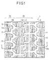
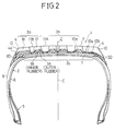
- Figs. 1 to 3 show a first embodiment of the pneumatic tire according to the present invention.
- a pneumatic tire (tire size: 165 SR13) 1 includes a tire case 2, and a tread portion 3 covering a crown portion 2a of the case 2 between two shoulder portions 4.
- the case 2 comprises a pair of bead portions 5, a carcass 6 made of rubber coated cords arranged substantially in the tire radial direction between the two bead portions 5, and a belt layer 7 arranged substantially in the tire circumferential direction outside the crown portion 2a of the carcass 6.
- side walls 8 are formed on both the axially outsides of the carcass 6 of the case 2.
- the tread portion 3 is composed of an outer rubber layer 3A arranged radially outward so as to be in contact with road surface and an inner rubber layer 3B arranged radially inward, and side rubber portions 3D for covering both the sides of the tread portion 3.
- the side rubber portion 3D is ordinary rubber including no foaming agent and, as shown in Figs. 2 and 3, covers the tread portion 3 to a position 4a on the side wall 8 or a position 10b of a bottom of lateral groove 10. Further, it is also possible to design the side rubber portion 3D so as to cover the shoulder portion 4 to an axially outside part 4b of the tread portion 3 as shown in Fig. 4.
- the above tread portion 3 can be manufactured by simultaneously extruding three rubbers of outer rubber layer; the inner rubber layer 3B and two relatively thin side rubber portions 3D from an extrusion machine into a trapezoidal (in cross section) shape in multilayer state or by separately extruding three rubber layers into three pieces of sheet, separately before bonding these rubbers.
- the volume V 3A of the outer rubber layer 3A is 60% of the total volume V of the tread 3.
- the tread 3 is formed with a plurality of lateral grooves 10 extending in the lateral direction of the tread 3 and arranged with approximately regular intervals in the tire circumferential direction at both side areas 3a and the central area 3b.
- the tread portion 3 is formed with two straight circumferential grooves 11A at the central area 3b and two zigzag circumferential grooves 11B at both the side areas 3a so as to form block-shaped land portions 12.
- Sipes 15 are formed in the tire lateral direction on the land portion 12.
- the inner rubber layer 3B is made of an ordinary rubber having composition 2 as shown in Table 1.
- the side walls 8 are an ordinary side wall rubber excellent in antibending performance.
- the side rubber portions 3D are the ordinary rubber whose foam rate V is smaller than that of the outer rubber layer (i.e. excellent in antibendability and anticutting performance). In this embodiment, in practice, the side rubber portions 3D are made of the ordinary rubber of zero foam rate.
- the foam rubber 17 of the rubber composition 1 as shown in Table 1 includes rubber components composed of polymer whose glass transition temperature is -60 o C or lower (e.g. natural rubber whose glass transition temperature is -72 o C), styrene butadiene rubber whose glass transition temperature is -73 o C, and polybutadiene rubber whose glass transition temperature is -100 o C and mixed with an ordinary compounding agent and foaming agent (dinitropentamethylene-tetraamine and urea).
- polymer whose glass transition temperature is -60 o C or lower e.g. natural rubber whose glass transition temperature is -72 o C
- styrene butadiene rubber whose glass transition temperature is -73 o C
- polybutadiene rubber whose glass transition temperature is -100 o C and mixed with an ordinary compounding agent and foaming agent (dinitropentamethylene-tetraamine and urea).
- the tires are formed, heated, pressurized, vulcanized and depressurized within a vulcanizing mold in accordance with the ordinary tire manufacturing method.
- the foam rubber includes independent bubbles (shown by black points in the drawing) 18 when expanded.
- the foam rubber 17 (Composition 1) used for the embodiment is 22% in foam rate V, and has independent bubbles whose average diameter is 32 um and 84 independent bubbles whose diameters are from 30 to 200 »m per unit area 1mm2.
- the construction and the manufacturing method of those components other than the tread 3 are the same as in the ordinary pneumatic tires, and therefore description thereof is omitted herein.
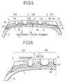
- Fig. 5 shows a second embodiment of the present invention.
- foam rubber is effectively distributed on the outer rubber layer 3A of the tread portion 3 in such a way that the foam rate V A (15%) of the foam rubber 17A at both side areas 13A (each of which corresponds to 5 to 25% of the tread width) of the outer rubber layer 3A is smaller than that V B (22%) of the foam rubber 17B at the central area 13B partitioned by a boundary 22 parallel to an equatorial plane E from the side area 13A.
- the Side rubber portions 3D are ordinary rubber which covers both sides of the tread portion 3. The portions other than the above are the same as in the first embodiment.
- the rubber composition of the foam rubber 17A is the same as composition 1 shown in Table 1 except the foaming agent (DPT) of 2.0 and assistant (urea) of 2.0.
- the physical properties of this foam rubber is 15% in foam rate V, 30 »m in average bubble diameter, 62 pieces in the number of independent bubbles, 5.4 x 10 dyn/cm2 in dynamic elastic modulus, and 47 degrees in hardness.
- the composition of the foam rubber 17B is the same as the composition 1.
- the second embodiment has been explained for the case where the boundary 22 is parallel to the equatorial plane E.
- the present embodiment can be applied to the case where the boundary 22 is inclined in cross section toward the right or the left with respect to the equatorial plane E.
- Fig. 6 shows a third embodiment of the present invention.
- the boundary surface 22 of the second embodiment is inclined deep in cross section from near the shoulder portion 4 to the center of the tread 3.
- the thickness of the outer rubber layer is approximately the same in cross section at both the side areas and the central area.
- Fig. 7 shows a fourth embodiment, in which the thickness D 3A of the outer rubber layer 3A at the center of the groove bottom 10c of the lateral groove 10 is 70 to 10% of a thickness D3 between the lateral groove bottom surface 10d and the belt layer 7, and more preferably 50 to 30% thereof.
- the reason why the thickness of the outer rubber layer is defined at the groove bottom will be described hereinbelow with reference to Figs. 8 and 9.
- the number N of bubbles per unit tire cross-sectional area at the groove bottom 10a of the outer foam rubber layer 3A changes, as shown in Fig. 9, along the groove central line from the groove bottom surface 10d in the thickness direction of the outer rubber layer 3A.
- the number N of bubbles in the outer rubber layer 3A decreases near the groove bottom surface 10d and near the boundary between the outer and inner rubber layers 3A and 3B but increases at the middle portion of the outer rubber layer 3A.
- the number of bubbles in the outer rubber layer 3A at the land portion is substantially constant in the thickness direction of the outer rubber layer 3A.
- the foam rate V of the outer rubber layer at the land portion was 22% and the thickness ratio D 3A /D3 of the outer and total thickness at the groove bottom portion was 36% ( 0.8mm)
- the foam rate V of the outer rubber layer at the middle portion thereof along the central line of the groove bottom portion was 15%.
- the thickness ratio D 3A /D3 lies in a range from 70 to 10%
- the thickness D L of the outer rubber layer 3A at the land portion 12 is 15 to 85 % of the depth D10 of the groove, and more preferably 30 to 70 % thereof.
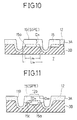
- Fig. 10 shows a fifth embodiment, in which sipes (or incisions) 15 (also shown in Fig. 1) formed in the tread extend beyond the major part of the outer rubber layer 3A in the groove depth direction and further into the inner rubber layer 3B.
- the depth D15 of the sipes 15 is uniform over the entire length L 15a , and extends into the inner rubber layer 3B at a partial length L 15b of the land portion 12 at the middle thereof.
- Fig. 11 shows a sixth embodiment, in which the depth D 25A of the sipe 15 at the middle portion 15a of the land portion is deeper than that D15 of the sipe 15 on both sides 15c of the land portion 12.
- the width of the sipe is up to 3 mm, and preferably 0.3 to 1.5 mm.
- sipes each of whose both ends are open to the grooves as shown in Figs. 10 and 11; sipes each of whose one end is open to the groove and each of whose other end is closed as shown in Fig. 1; sipes each of whose both ends are closed; straight sipes, zigzag sipes, wave-shaped sipes, etc.
- a number of small circles described at one end and the middle portion of each of sipes are holes connected to sipes and extending in the same depth direction as the sipes.
- Fig. 12 shows a seventh embodiment, in which the outer rubber layer 3A is entirely covered by a cover layer 9.
- This cover layer 9 is a thin ordinary rubber layer (not a foam rubber layer) with a thickness of 1 mm or less, more preferably 0.3 to 0.5 mm.
- the cover layer 9 it is possible to effectively reinforce the lateral groove bottoms 10b and 10c and therefore prevent crack generation thereat. Further, it is also possible to cover only the groove bottoms of specific grooves, so far as circumstances permit, by the covering layer 9.
- the test tires of ordinary structure were used for comparison tests as shown in Table 2.
- the invention tires were formed with a tread as shown in Figs. 1 and 2, and the comparison tires 1 and 2 were formed with a tread as shown in Fig. 1 (the groove dimensions were the same as in the invention tires).
- the tread rubber material of the invention tires was compositions 1 and 2 shown in Table 1; that of the comparison tires was composition 3 (ice compound) shown in Table 1; and that of the comparison tires was composition 1 (foam rubber) shown in Table 1 in only the tread surface portion.
- the comparison tires 1 and 2 were basically the same as the invention tire except the above.
- Tests have been effected in accordance with the above-mentioned test methods with respect to steerability, braking ability on ice, climbing ability on snow, riding comfortability, road noise performance, wear resistance and anticrack performance at groove bottoms.
- Table 2 Comparison 1 Comparison 2 Invention Rubber kinds Ice compound Foam rubber Foam rubber and ordinary rubber Tread structure Single rubber layer Single rubber layer Double rubber layers Steerability 100 85 97 Braking ability on ice 100 110 110 Climbing ability on snow 100 108 110 Riding Comfortability 100 110 107 Road noise 1dB(A)less than Comparison 1 1dB(A)less than Comparison 1 Antiabrasion 100 85 100 Anticrack at groove bottoms No crack Many cracks No crack
- the test results are shown with the indices of the comparison 1 as 100 in Table 2.
- the tires of the present invention have less crack occurrence at groove bottoms as compared with the comparison tires 1 and 2, thus improving the tire performance markedly. That is, it is possible to markedly improve the tire performance during travelling in winter, while maintaining tire performance during travelling in summer.
Landscapes
- Engineering & Computer Science (AREA)
- Mechanical Engineering (AREA)
- Tires In General (AREA)
Claims (15)
- Luftreifen, der einen Laufflächenbereich (3) hat, der aus mindestens zwei Gummischichten besteht, und zwar einer radial außen angeordneten, äußeren Gummischicht (3A), die aus Schaumgummi besteht, dessen Schaumanteil 5 bis 50% beträgt, und dessen Volumenverhältnis bezüglich des Laufflächenbereichs mindestens 10% beträgt, und einer radial innen angeordneten, inneren Gummischicht (3B), die eine Shore-A-Härte von 54 bis 80 Grad hat, die größer als diejenige der äußeren Gummischicht (3A) ist, und Laufflächen-Seitenbereiche hat, mit biege- und schneidfesten Seitengummis (3D) zum Bedecken beider Seiten des Laufflächenbereichs (3), und der mit einer Vielzahl von seitlichen Rillen (10), einer Vielzahl von Umfangsrillen (11A, 11B), und einer Vielzahl von blockförmigen Stollenbereichen (12) gebildet ist, die durch die seitlichen Rillen und die Umfangsrillen festgelegt sind, wobei jeder der Stollenbereiche sich seitlich erstreckende Einschnitte (15) hat, dadurch gekennzeichnet, daß jeder der Seitengummis (3D) aus Gummi besteht, der kein Schäummittel enthält, und sich von der Seite der Lauffläche (3) in die seitlichen Rillen (10) hinein erstreckt, um den Boden der seitlichen Rillen zu bedecken; daß auf dem Boden der seitlichen Rillen, der von den Seitengummis bedeckt ist, keilförmige Bereiche der äußeren Schaumgummischicht (3A), die einen verringerten Schaumanteil haben, zwischen dem Seitengummi (3D) und der inneren Gummischicht (3B) gebildet sind; und daß die Einschnitte (15) in den Stollenbereichen sich durch die äußere Gummischicht (3A) hindurch in die innere Gummischicht (3B) erstrecken.
- Luftreifen gemäß Anspruch 1, dadurch gekennzeichnet, daß das Verhältnis des Volumens der äußeren Gummischicht (3A) zu dem Volumen der Lauffläche 10 bis 70%, vorzugsweise 40 bis 60% beträgt.
- Luftreifen gemäß Anspruch 1 oder 2, dadurch gekennzeichnet, daß die Härte der äußeren Gummischicht (3A) 35 bis 53 Grad beträgt.
- Luftreifen gemäß irgendeinem der Ansprüche 1 bis 3, dadurch gekennzeichnet, daß der Schaumanteil der äußeren Gummischicht (3A) 5 bis 30% beträgt.
- Luftreifen gemäß irgendeinem der Ansprüche 1 bis 4, dadurch gekennzeichnet, daß der mittlere Blasendurchmesser der äußeren Schaumgummischicht 5 bis 150 »m, vorzugsweise 10 bis 100 »m beträgt.
- Luftreifen gemäß irgendeinem der Ansprüche 1 bis 5, dadurch gekennzeichnet, daß die Anzahl der Blasen mit 30 bis 120 »m Durchmesser pro Flächeneinheit von 1 mm² in der äußeren Schaumgummischicht in einem mittleren Bereich der Reifenstollenbereiche (12) mindestens 20, vorzugsweise mindestens 30 beträgt.
- Luftreifen gemäß irgendeinem der Ansprüche 1 bis 6, dadurch gekennzeichnet, daß der Schaumgummi in der äußeren Gummischicht (3A) des Laufflächenbereichs (3) so verteilt ist, daß ein Schaumanteil VA des Schaumgummis (17A) in den beiden Seitenzonen (13A) der äußeren Gummischicht (3A) kleiner als der Schaumanteil VB des Schaumgummis (17B) in der durch eine zu der Äquatorebene E parallele Grenzfläche (22) von der Seitenzone (13A) getrennten, mittleren Zone (13B) ist, um die Steifigkeit der Reifenschulterbereiche zu erhöhen.
- Luftreifen gemäß irgendeinem der Ansprüche 1 bis 6, dadurch gekennzeichnet, daß der Schaumgummi in der äußeren Gummischicht (3A) des Laufflächenbereichs (3) so verteilt ist, daß der Schaumanteil VA des Schaumgummis (17A) in den beiden Seitenzonen (13A) der äußeren Gummischicht (3A) kleiner ist als der Schaumanteil VB des Schaumgummis (17B) in der mittleren Zone (13B), die durch eine Grenzfläche (22) getrennt ist, die im Querschnitt von nahe bei dem Reifenschulterbereich (4) zu der Mitte der Lauffläche (3) hin tief abfällt.
- Luftreifen gemäß irgendeinem der Ansprüche 1 bis 8, dadurch gekennzeichnet, daß die Dicke D3A der äußeren Gummischicht (3A) in der Mitte des Rillenbodens (10c) der seitlichen Rille (10) 70 bis 10%. vorzugsweise 50 bis 30%, der Dicke D₃ zwischen der Rillenbodenoberfläche (10d) und der Gürtelschicht (7) beträgt.
- Luftreifen gemäß irgendeinem der Ansprüche 1 bis 9, dadurch gekennzeichnet, daß die Dicke DL der äußeren Gummischicht (3A) bei einem Stollenbereich (12) zwischen der Reifenoberfläche und einer Grenzlinie L 15 bis 85%, vorzugsweise 30 bis 70%, der Tiefe D₁₀ einer Rille (10) beträgt.
- Luftreifen gemäß irgendeinem der Ansprüche 1 bis 10, dadurch gekennzeichnet, daß die Tiefe D₁₅ des Einschnitts (15) über die ganze Länge L15a gleich groß ist und sich bei einer Teillänge L15b eines Stollenbereichs in der Mitte dieses Stollenbereichs in die innere Gummischicht (3B) erstreckt.
- Luftreifen gemäß irgendeinem der Ansprüche 1 bis 10, dadurch gekennzeichnet, daß die Tiefe D25A des Einschnitts (15) in einem mittleren Bereich (15a) des Stollenbereichs größer als die Tiefe D₁₅ der Einschnitte (15) auf den beiden Seiten (15c) des Stollenbereichs ist.
- Luftreifen gemäß irgendeinem der Ansprüche 1 bis 12, dadurch gekennzeichnet, daß die äußere Gummischicht (3A) von einer Deckschicht (9) bedeckt ist, die eine Dicke von 0.3 bis 0.4 mm hat und aus einem gewöhnlichen Gummi besteht.
- Luftreifen gemäß irgendeinem der Ansprüche 1 bis 12, dadurch gekennzeichnet, daß nur die Rillenböden (10a, 10b, 10c) der äußeren Gummischicht (3A) von einer Deckschicht (9) bedeckt sind, die eine Dicke von 0,3 bis 0,4 mm hat und aus einem gewöhnlichen Gummi besteht.
- Luftreifen gemäß irgendeinem der Ansprüche 1 bis 14, dadurch gekennzeichnet, daß Bereiche mit geringerer Dicke der äußeren Gummischicht (3A) zwischen dem Boden der seitlichen Rillen (10) und der inneren Gummischicht (3B) gebildet sind, und der Schaumanteil der Bereiche mit geringerer Dicke der äußeren Gummischicht (3A) kleiner als der Schaumanteil der äußeren Gummischicht (3A) bei den Stollenbereichen der Lauffläche ist.
Applications Claiming Priority (8)
| Application Number | Priority Date | Filing Date | Title |
|---|---|---|---|
| JP92296/88 | 1988-04-13 | ||
| JP63092296A JPH01262203A (ja) | 1988-04-13 | 1988-04-13 | 空気入りタイヤ |
| JP63123686A JPH01293205A (ja) | 1988-05-19 | 1988-05-19 | 空気入りタイヤ |
| JP123686/88 | 1988-05-19 | ||
| JP63127669A JPH01297303A (ja) | 1988-05-24 | 1988-05-24 | 空気入りタイヤ |
| JP127669/88 | 1988-05-24 | ||
| JP146649/88 | 1988-06-13 | ||
| JP63146649A JPH01314607A (ja) | 1988-06-13 | 1988-06-13 | 空気入りタイヤ |
Publications (3)
| Publication Number | Publication Date |
|---|---|
| EP0337787A2 EP0337787A2 (de) | 1989-10-18 |
| EP0337787A3 EP0337787A3 (en) | 1990-09-05 |
| EP0337787B1 true EP0337787B1 (de) | 1995-06-21 |
Family
ID=27468021
Family Applications (1)
| Application Number | Title | Priority Date | Filing Date |
|---|---|---|---|
| EP89303690A Expired - Lifetime EP0337787B1 (de) | 1988-04-13 | 1989-04-13 | Luftreifen |
Country Status (5)
| Country | Link |
|---|---|
| EP (1) | EP0337787B1 (de) |
| KR (1) | KR950008874B1 (de) |
| CA (1) | CA1332145C (de) |
| DE (1) | DE68923117T2 (de) |
| ES (1) | ES2076206T3 (de) |
Families Citing this family (14)
| Publication number | Priority date | Publication date | Assignee | Title |
|---|---|---|---|---|
| FI944892L (fi) * | 1993-11-18 | 1995-08-18 | Bridgestone Corp | Pneumaattinen rengas |
| US6408911B1 (en) * | 1995-06-08 | 2002-06-25 | Bridgestone Corporation | Studless pneumatic tire including block-shaped island portions each having sipes |
| KR970033950A (ko) * | 1995-12-22 | 1997-07-22 | 원본미기재 | 공기주입 타이어 |
| EP0820885A3 (de) * | 1996-07-24 | 1998-07-08 | Bridgestone Corporation | Luftreifen |
| EP1035979A1 (de) * | 1998-01-26 | 2000-09-20 | Michelin Recherche Et Technique S.A. | Reifen mit rillenflankenbelag zur reduzierung von anomalien, die subjektiv unzufriedenheit des benutzers verursachen |
| WO2000053437A1 (en) * | 1999-01-21 | 2000-09-14 | Michelin Recherche Et Technique S.A. | Tire having a groove wall lining for reducing formation of anomalies causing subjective user dissatisfaction |
| FR2974539B1 (fr) * | 2011-04-28 | 2013-12-06 | Michelin Rech Tech | Pneumatique comprenant une bande de roulement avec un materiau alveolaire |
| FR2988728B1 (fr) * | 2012-04-02 | 2014-04-11 | Michelin & Cie | Pneumatique dont la zone sommet est pourvue d'une sous-couche comportant un elastomere thermoplastique |
| FR2993889B1 (fr) | 2012-07-27 | 2014-08-22 | Michelin & Cie | Composition de caoutchouc thermo-expansible pour pneumatique |
| FR3009306B1 (fr) | 2013-07-30 | 2015-07-31 | Michelin & Cie | Pneu dont la zone sommet est pourvue d’une couche interne reduisant les bruits de roulage |
| FR3009305A1 (fr) | 2013-07-30 | 2015-02-06 | Michelin & Cie | Composition de caoutchouc thermo-expansible et pneumatique comportant une telle composition |
| CN108501621B (zh) * | 2018-06-04 | 2024-01-23 | 青岛富耐特矿业科技有限公司 | 一种高性能特种填充式实心轮胎 |
| US11993110B2 (en) * | 2018-12-19 | 2024-05-28 | The Goodyear Tire & Rubber Company | Reinforced tread and method of forming |
| KR102127453B1 (ko) * | 2018-12-26 | 2020-06-26 | 넥센타이어 주식회사 | 공기입 타이어 |
Family Cites Families (5)
| Publication number | Priority date | Publication date | Assignee | Title |
|---|---|---|---|---|
| DE1194721B (de) * | 1960-06-07 | 1965-06-10 | Phoenix Gummiwerke Ag | Laufstreifen von Kraftfahrzeugluftreifen |
| US4249588A (en) * | 1978-04-27 | 1981-02-10 | The Goodyear Tire & Rubber Company | Pneumatic tire |
| GB2044191B (en) * | 1979-03-16 | 1983-03-09 | Dunlop Ltd | Tyres |
| US4381810A (en) * | 1981-05-22 | 1983-05-03 | The Goodyear Tire & Rubber Company | Tire with dual tread compound |
| DE3703480A1 (de) * | 1986-02-05 | 1987-08-06 | Bridgestone Corp | Luftreifen |
-
1989
- 1989-04-12 CA CA000596436A patent/CA1332145C/en not_active Expired - Lifetime
- 1989-04-13 KR KR1019890004917A patent/KR950008874B1/ko not_active Expired - Lifetime
- 1989-04-13 EP EP89303690A patent/EP0337787B1/de not_active Expired - Lifetime
- 1989-04-13 ES ES89303690T patent/ES2076206T3/es not_active Expired - Lifetime
- 1989-04-13 DE DE68923117T patent/DE68923117T2/de not_active Expired - Lifetime
Also Published As
| Publication number | Publication date |
|---|---|
| EP0337787A2 (de) | 1989-10-18 |
| KR950008874B1 (ko) | 1995-08-09 |
| CA1332145C (en) | 1994-09-27 |
| KR900015954A (ko) | 1990-11-12 |
| EP0337787A3 (en) | 1990-09-05 |
| DE68923117T2 (de) | 1996-02-15 |
| ES2076206T3 (es) | 1995-11-01 |
| DE68923117D1 (de) | 1995-07-27 |
Similar Documents
| Publication | Publication Date | Title |
|---|---|---|
| US5176765A (en) | Pneumatic tire having outer tread layer of foam rubber | |
| CN1326716C (zh) | 具有由至少两种胶料形成的胎面花纹单元的胎面 | |
| EP0337787B1 (de) | Luftreifen | |
| EP0320215B1 (de) | Radialer Reifen | |
| CN103998256B (zh) | 用于充气轮胎的胎面 | |
| EP1097825B1 (de) | Spikeloser Luftreifen | |
| JPH11301217A (ja) | 空気入りタイヤ | |
| CN101181862A (zh) | 充气轮胎 | |
| JP3273772B2 (ja) | スタッドレスタイヤ | |
| JP3401283B2 (ja) | 空気入りタイヤ | |
| EP0590916B1 (de) | Luftreifen | |
| EP0572127A1 (de) | Luftreifen mit einer doppelschichtigen Lauffläche | |
| JP3352064B2 (ja) | スタッドレスタイヤ | |
| JPH04218405A (ja) | 空気入りタイヤ | |
| JPH0640213A (ja) | 空気入りタイヤ | |
| JP3270521B2 (ja) | ブロック及び空気入りタイヤ | |
| JPH0565003A (ja) | 空気入りタイヤ | |
| JPH01297302A (ja) | 空気入りタイヤ | |
| JP4014492B2 (ja) | 乗用車用空気入りタイヤ | |
| JPH01293205A (ja) | 空気入りタイヤ | |
| JP2661920B2 (ja) | 空気入りタイヤ | |
| JP3576609B2 (ja) | 空気入りタイヤ | |
| JPH0776202A (ja) | 空気入りタイヤ | |
| JP2564760B2 (ja) | 空気入りタイヤ | |
| JP3352063B2 (ja) | スタッドレスタイヤ |
Legal Events
| Date | Code | Title | Description |
|---|---|---|---|
| PUAI | Public reference made under article 153(3) epc to a published international application that has entered the european phase |
Free format text: ORIGINAL CODE: 0009012 |
|
| 17P | Request for examination filed |
Effective date: 19890508 |
|
| AK | Designated contracting states |
Kind code of ref document: A2 Designated state(s): CH DE ES FR GB IT LI LU |
|
| PUAL | Search report despatched |
Free format text: ORIGINAL CODE: 0009013 |
|
| AK | Designated contracting states |
Kind code of ref document: A3 Designated state(s): CH DE ES FR GB IT LI LU |
|
| 17Q | First examination report despatched |
Effective date: 19920519 |
|
| GRAA | (expected) grant |
Free format text: ORIGINAL CODE: 0009210 |
|
| AK | Designated contracting states |
Kind code of ref document: B1 Designated state(s): CH DE ES FR GB IT LI LU |
|
| ITF | It: translation for a ep patent filed | ||
| REF | Corresponds to: |
Ref document number: 68923117 Country of ref document: DE Date of ref document: 19950727 |
|
| ET | Fr: translation filed | ||
| REG | Reference to a national code |
Ref country code: ES Ref legal event code: FG2A Ref document number: 2076206 Country of ref document: ES Kind code of ref document: T3 |
|
| PLBE | No opposition filed within time limit |
Free format text: ORIGINAL CODE: 0009261 |
|
| STAA | Information on the status of an ep patent application or granted ep patent |
Free format text: STATUS: NO OPPOSITION FILED WITHIN TIME LIMIT |
|
| 26N | No opposition filed | ||
| REG | Reference to a national code |
Ref country code: GB Ref legal event code: IF02 |
|
| PGFP | Annual fee paid to national office [announced via postgrant information from national office to epo] |
Ref country code: ES Payment date: 20080423 Year of fee payment: 20 Ref country code: CH Payment date: 20080415 Year of fee payment: 20 Ref country code: FR Payment date: 20080312 Year of fee payment: 20 Ref country code: LU Payment date: 20080416 Year of fee payment: 20 Ref country code: DE Payment date: 20080417 Year of fee payment: 20 |
|
| PGFP | Annual fee paid to national office [announced via postgrant information from national office to epo] |
Ref country code: IT Payment date: 20080428 Year of fee payment: 20 |
|
| PGFP | Annual fee paid to national office [announced via postgrant information from national office to epo] |
Ref country code: GB Payment date: 20080416 Year of fee payment: 20 |
|
| REG | Reference to a national code |
Ref country code: CH Ref legal event code: PL |
|
| REG | Reference to a national code |
Ref country code: GB Ref legal event code: PE20 Expiry date: 20090412 |
|
| REG | Reference to a national code |
Ref country code: ES Ref legal event code: FD2A Effective date: 20090414 |
|
| PG25 | Lapsed in a contracting state [announced via postgrant information from national office to epo] |
Ref country code: ES Free format text: LAPSE BECAUSE OF EXPIRATION OF PROTECTION Effective date: 20090414 |
|
| PG25 | Lapsed in a contracting state [announced via postgrant information from national office to epo] |
Ref country code: GB Free format text: LAPSE BECAUSE OF EXPIRATION OF PROTECTION Effective date: 20090412 |