EP0337939B1 - Capteur inductif et appareil de mesure pour obtenir la position relative d'un capteur - Google Patents
Capteur inductif et appareil de mesure pour obtenir la position relative d'un capteur Download PDFInfo
- Publication number
- EP0337939B1 EP0337939B1 EP19890810201 EP89810201A EP0337939B1 EP 0337939 B1 EP0337939 B1 EP 0337939B1 EP 19890810201 EP19890810201 EP 19890810201 EP 89810201 A EP89810201 A EP 89810201A EP 0337939 B1 EP0337939 B1 EP 0337939B1
- Authority
- EP
- European Patent Office
- Prior art keywords
- arrangement
- receiver
- coil
- winding portions
- detection region
- Prior art date
- Legal status (The legal status is an assumption and is not a legal conclusion. Google has not performed a legal analysis and makes no representation as to the accuracy of the status listed.)
- Expired - Lifetime
Links
- 230000001939 inductive effect Effects 0.000 title claims description 7
- 238000004804 winding Methods 0.000 claims description 124
- 238000001514 detection method Methods 0.000 claims description 21
- 230000005672 electromagnetic field Effects 0.000 claims description 11
- 238000011156 evaluation Methods 0.000 claims description 7
- 230000006698 induction Effects 0.000 claims description 5
- 230000001419 dependent effect Effects 0.000 claims description 3
- 230000008878 coupling Effects 0.000 claims description 2
- 238000010168 coupling process Methods 0.000 claims description 2
- 238000005859 coupling reaction Methods 0.000 claims description 2
- 239000002184 metal Substances 0.000 claims description 2
- 238000010276 construction Methods 0.000 claims 1
- 230000001788 irregular Effects 0.000 claims 1
- 238000013459 approach Methods 0.000 description 2
- 239000000969 carrier Substances 0.000 description 2
- 238000012937 correction Methods 0.000 description 2
- 238000013461 design Methods 0.000 description 2
- 230000000694 effects Effects 0.000 description 2
- 238000005516 engineering process Methods 0.000 description 2
- 230000010363 phase shift Effects 0.000 description 2
- 239000012876 carrier material Substances 0.000 description 1
- 239000004020 conductor Substances 0.000 description 1
- 230000007423 decrease Effects 0.000 description 1
- 230000004069 differentiation Effects 0.000 description 1
- 238000005259 measurement Methods 0.000 description 1
- 238000012545 processing Methods 0.000 description 1
- 230000035945 sensitivity Effects 0.000 description 1
- 238000012549 training Methods 0.000 description 1
Images
Classifications
-
- G—PHYSICS
- G01—MEASURING; TESTING
- G01B—MEASURING LENGTH, THICKNESS OR SIMILAR LINEAR DIMENSIONS; MEASURING ANGLES; MEASURING AREAS; MEASURING IRREGULARITIES OF SURFACES OR CONTOURS
- G01B7/00—Measuring arrangements characterised by the use of electric or magnetic techniques
- G01B7/02—Measuring arrangements characterised by the use of electric or magnetic techniques for measuring length, width or thickness
- G01B7/023—Measuring arrangements characterised by the use of electric or magnetic techniques for measuring length, width or thickness for measuring distance between sensor and object
-
- G—PHYSICS
- G01—MEASURING; TESTING
- G01D—MEASURING NOT SPECIALLY ADAPTED FOR A SPECIFIC VARIABLE; ARRANGEMENTS FOR MEASURING TWO OR MORE VARIABLES NOT COVERED IN A SINGLE OTHER SUBCLASS; TARIFF METERING APPARATUS; MEASURING OR TESTING NOT OTHERWISE PROVIDED FOR
- G01D5/00—Mechanical means for transferring the output of a sensing member; Means for converting the output of a sensing member to another variable where the form or nature of the sensing member does not constrain the means for converting; Transducers not specially adapted for a specific variable
- G01D5/12—Mechanical means for transferring the output of a sensing member; Means for converting the output of a sensing member to another variable where the form or nature of the sensing member does not constrain the means for converting; Transducers not specially adapted for a specific variable using electric or magnetic means
- G01D5/14—Mechanical means for transferring the output of a sensing member; Means for converting the output of a sensing member to another variable where the form or nature of the sensing member does not constrain the means for converting; Transducers not specially adapted for a specific variable using electric or magnetic means influencing the magnitude of a current or voltage
- G01D5/20—Mechanical means for transferring the output of a sensing member; Means for converting the output of a sensing member to another variable where the form or nature of the sensing member does not constrain the means for converting; Transducers not specially adapted for a specific variable using electric or magnetic means influencing the magnitude of a current or voltage by varying inductance, e.g. by a movable armature
- G01D5/22—Mechanical means for transferring the output of a sensing member; Means for converting the output of a sensing member to another variable where the form or nature of the sensing member does not constrain the means for converting; Transducers not specially adapted for a specific variable using electric or magnetic means influencing the magnitude of a current or voltage by varying inductance, e.g. by a movable armature differentially influencing two coils
- G01D5/2208—Mechanical means for transferring the output of a sensing member; Means for converting the output of a sensing member to another variable where the form or nature of the sensing member does not constrain the means for converting; Transducers not specially adapted for a specific variable using electric or magnetic means influencing the magnitude of a current or voltage by varying inductance, e.g. by a movable armature differentially influencing two coils by influencing the self-induction of the coils
-
- G—PHYSICS
- G01—MEASURING; TESTING
- G01D—MEASURING NOT SPECIALLY ADAPTED FOR A SPECIFIC VARIABLE; ARRANGEMENTS FOR MEASURING TWO OR MORE VARIABLES NOT COVERED IN A SINGLE OTHER SUBCLASS; TARIFF METERING APPARATUS; MEASURING OR TESTING NOT OTHERWISE PROVIDED FOR
- G01D5/00—Mechanical means for transferring the output of a sensing member; Means for converting the output of a sensing member to another variable where the form or nature of the sensing member does not constrain the means for converting; Transducers not specially adapted for a specific variable
- G01D5/12—Mechanical means for transferring the output of a sensing member; Means for converting the output of a sensing member to another variable where the form or nature of the sensing member does not constrain the means for converting; Transducers not specially adapted for a specific variable using electric or magnetic means
- G01D5/14—Mechanical means for transferring the output of a sensing member; Means for converting the output of a sensing member to another variable where the form or nature of the sensing member does not constrain the means for converting; Transducers not specially adapted for a specific variable using electric or magnetic means influencing the magnitude of a current or voltage
- G01D5/20—Mechanical means for transferring the output of a sensing member; Means for converting the output of a sensing member to another variable where the form or nature of the sensing member does not constrain the means for converting; Transducers not specially adapted for a specific variable using electric or magnetic means influencing the magnitude of a current or voltage by varying inductance, e.g. by a movable armature
- G01D5/22—Mechanical means for transferring the output of a sensing member; Means for converting the output of a sensing member to another variable where the form or nature of the sensing member does not constrain the means for converting; Transducers not specially adapted for a specific variable using electric or magnetic means influencing the magnitude of a current or voltage by varying inductance, e.g. by a movable armature differentially influencing two coils
- G01D5/225—Mechanical means for transferring the output of a sensing member; Means for converting the output of a sensing member to another variable where the form or nature of the sensing member does not constrain the means for converting; Transducers not specially adapted for a specific variable using electric or magnetic means influencing the magnitude of a current or voltage by varying inductance, e.g. by a movable armature differentially influencing two coils by influencing the mutual induction between the two coils
Definitions
- the invention relates to an inductive sensor arrangement according to the preamble of claim 1 and its use in a measuring arrangement according to the preamble of claim 7 or 8.
- a sensor arrangement is e.g. known from the applicant's EP-A-98 238.
- an alternating field is induced in a plurality of receiver coils by at least one transmitter coil fed by an RF oscillator.
- This is influenced by the approach of a metallic object into an object detection area, ie into the electromagnetic field.
- This also influences the induced voltage in the receiver partial windings, whereby both phase shifts in the individual partial windings and amplitude fluctuations can occur.
- This alternating field generated by the transmitter coil thus induces an alternating voltage which is dependent on the position of the object in the object detection area in the partial windings of the receiver coil arrangement.
- the receiver coil is subdivided into two or more partial windings which, when the object changes position, move away from or approach the object differently. This results in a different field distribution of the RF fields and a phase shift in the two partial windings.
- the change in position of the object can be determined in the simplest way. The easiest way to do this is to connect the partial windings directly ("directly") with the opposite winding sense, so that remove the partial voltages of the partial windings, provided that they are influenced in the same way by the object.
- the two partial windings are influenced differently and the partial voltages are only partially compensated for, so that the receiver coil emits a usable output signal. Since the position of the object also changes the inductance of the partial windings of the receiver coil, the change in position also results in a different inductance change of the two partial windings, so that a phase change in the AC voltage at the output of the receiver coil can be determined compared to the signal of the transmitter coil.
- the known sensor arrangement is suitable for scanning object irregularities, such as gaps in metal plates or weld seams and the like. It has proven useful that the partial windings are arranged perpendicular to the object on both sides of the object irregularity.
- the gap lies exactly in the middle between the two receiver partial windings, the same voltages and currents are induced, so that the system is in equilibrium and can be used, for example, in a control loop to track a seam or to find a hole.
- Difficulties can arise if, for example, when tracking a gap, the object on one side of the gap is closer to the receiver partial winding above it than the object on the other side of the gap in relation to the assigned partial winding.
- the electromagnetic field is not only influenced by the irregularity of the object, ie the gap, but is also asymmetrically damped by the different object spacing of the two partial windings.
- the object of the invention is therefore to create an inductive sensor arrangement or a measuring arrangement for determining the relative position of such a sensor arrangement to an object, in which distance errors e.g. are easier to compensate for when tracking seams or other object irregularities, so that the sensor arrangement can more accurately follow the actual course of the seam or the object irregularity.
- each of the two coil arrangements has only two receiver sub-coils - a typical arrangement for tracking gaps or weld seams.
- the arrangement is also identical to three, four or more Realize partial receiver windings per coil arrangement. Such arrangements are then typically used to find holes or other circular or point-shaped object irregularities.
- the invention therefore initially assumes that the partial windings of the first winding arrangements are directly or indirectly coupled in a known manner, so that the difference signal derived from the two partial windings corresponds to the lateral offset of the object irregularity.
- each of the partial windings of the first coil arrangement is assigned a partial winding of the second coil arrangement.
- the two partial windings are approximately aligned. Due to the different distance to the object, each change in distance of the object under the two aligned partial windings leads to a different change in the induction in the two partial windings.
- the comparison of these different changes in induction in the two partial windings lying one above the other can be used to obtain a signal corresponding to the distance of the object between the partial windings.
- This signal corresponds particularly precisely to the effective distance of the object to the partial winding of the first coil arrangement for measuring the lateral offset, because this partial winding is used both for the generation of lateral offset signals and - in connection with the partial winding of the second coil arrangement above it - for the acquisition of distance signals.
- the sensor arrangement can be implemented particularly easily if the partial windings of the first coil arrangement are directly connected to one another and at the same time are connected directly to the partial windings of the second coil arrangement in order to obtain the signals proportional to the distance.
- the invention can also be implemented if each of the individual Coils are derived and determined, for example, via an amplifier and / or rectifier, and then these signals are indirectly compared with one another or switched against one another.
- good sensitivity of the sensor arrangement can be achieved if the winding axes of the transmitter coil and the winding axes of the receiver coils are directed towards the object detection area or towards the object.
- a symmetrical, namely point-symmetrical or axially symmetrical arrangement of the partial windings is advantageously suitable for locating or tracking linear or point-shaped object irregularities.
- the partial windings of each coil arrangement should be arranged in one plane in relation to the object detection area. If the object has a different shape, and e.g. requires a cylindrical or angular object detection area (e.g. pipe seam tracking), the partial windings of the coil arrangements can also be arranged at any angle or curved, as is e.g. in EP-A-130 940 of the applicant.
- the partial windings can be designed with or without a core.
- What is essential here is the direct inductive coupling of the transmitter coil or transmitter coils and the entirety of the partial windings of the receiver coil arrangements in order to obtain precise signals corresponding to the lateral offset and the distance of the partial windings from the object.
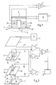
- FIG. 1 shows a known arrangement in which a transmitter coil 1 is arranged on a core 2.
- the transmitter coil 1 is fed by an HF oscillator 3 and generates an electromagnetic field which detects the core 2 and a metallic object 4a, 4b which lies in the area of influence of the electromagnetic field or the object detection area 5 of the transmitter coil 1.
- the side 4a of the object 4 lies closer to the core 2 than the side 4b of the object 4.
- the sides 4a, 4b of the object 4 are separated from one another by a slot 4c.
- Two receiver partial windings 6a, 6b are located in the electromagnetic field of the transmitter coil 1.
- the electromagnetic field of the transmitter coil would be absolutely uniform and would accordingly produce the same induction in terms of magnitude and voltage in the identically constructed and symmetrically arranged but sub-receiver partial windings 6a, 6b. In such a case, no signal was present at the input of an amplifier 7. However, the field of the transmitter coil 1 and also the subfields in the receiver partial windings 6a, 6b are changed by the object 4 and the eddy currents induced in the object. For example, an approximation of the slot 4c to one of the partial windings has the effect that it is damped less than the other partial winding.
- the signal of the less damped partial winding predominates and there is a distinguishable signal at the input of the amplifier 7.
- This signal can be used in a known manner, for example to control a readjustment device which, by means of evaluation and drive devices (not shown), moves the core 2 and / or the object 4 until no more signal is emitted by the amplifier 7 - which results in symmetrical conditions in the partial windings 6a, 6b and thus corresponds to a central alignment of the core 2 over the slot 4c.
- the receiver partial winding 6a is influenced to a greater extent, which is superimposed on the signal which is obtained from a center offset of the slot 4c relative to the core 2.
- Different distances a and b accordingly lead to a measurement error, which leads to misalignment of the core 2 relative to the slot 4c.
- FIG. 2 shows a schematic arrangement in which, for the sake of clarity, coils are only indicated with a single winding.
- a transmitter coil 1 is again provided, which is connected to an RF oscillator 3.
- a first coil arrangement 6 consists of two identical, but oppositely wound receiver partial windings 6a, 6b.
- the partial windings 6a, 6b are connected via lines 8a, 8b to an evaluation circuit indicated as an amplifier 7.
- a second coil arrangement 9 which likewise has two receiver partial windings 9a, 9b.
- the center tap 6c or 9c of the first coil arrangement 6 and the second coil arrangement 9 are connected to one another via a line 10. This causes the partial winding 6a and the partial winding 9a to be connected to one another.
- a signal can thus be tapped from line 8a and line 11, which corresponds to the difference between the signals induced by transmitter coil 1 in partial winding 9a and partial winding 6a. This difference signal is applied via line 8a and line 11 to the input of an amplifier 12.
- the windings 6b and 9b of the first coil arrangement 6 and the second coil arrangement 9 are connected to one another, so that a signal is present on lines 8b and 13 which results from the difference between the induction by the transmitter coil 1 and the partial winding 6b and 9b results.
- This signal is applied to the input of an amplifier 14. Since the object 4 is further away from the second coil arrangement 9 than from the first coil arrangement 6, a change in the distance of the object 4 leads to a weaker one Influencing the partial windings 9a, 9b as the partial windings 6a, 6b.
- the input signals at the amplifiers 12 and 14 thus correspond to the distance of the object 4 from the first coil arrangement 6a.
- the output signal of the amplifier 7, which should correspond to the lateral offset of the two partial windings 6a, 6b to the slot 4c, is compensated in such a way that differences in the distances a, b do not falsify the lateral offset measured value.
- correction signals can be derived in an optimally simple manner, which lead to an increase in the accuracy of the lateral offset signals. Since the partial windings 6a, 6b of the first coil arrangement both for obtaining the lateral offset signal by means of amplifier 7 and for obtaining the relative distance signals by means of amplifier 12, 14 and Ver 15 are used, it is ensured that the distance signals obtained actually correspond to the respective object distance of the partial windings 6a, 6b.
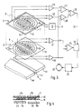
- FIG. 3 shows an embodiment in which the same components are provided with the same reference numerals.
- the partial windings 6a, 6b and 9a, 9b and the transmitter coil 1 are arranged as flat layers on insulating carrier disks 18, 19.
- the partial windings 6a, 6b, 9a, 9b are each formed axially symmetrically with respect to an axis of symmetry X.
- the mode of operation of the arrangement is analogous to the circuit arrangement according to FIG. 2. The only difference is that the partial windings 6a, 6b and 9a, 9b are not connected directly to one another but are each connected individually to signal amplifiers 20, 21, 22 and 23.
- a shift of the slot 4c from the region of the axis of symmetry X leads to the partial windings 6a and 6b delivering a different output signal to the amplifiers 20, 21.
- the lateral offset signal obtained in this way is determined in the comparison arrangement 24 and, via the compensation circuit 16, is applied to a schematically represented controller 25, which controls a tracking motor until the object 4 is again exactly below the axis of symmetry with the slot 4c by means of a mechanical tracking device, not shown X lies.
- the evaluation circuit is the receiver part Winding 6a connected to the partial winding 9a of the second coil arrangement in the following way:
- the partial winding 9a is connected on the output side to the signal amplifier 23, which in turn is connected to one input of a comparator 27.
- the signal amplifier 20 connected to the partial winding 6a is connected on the output side to the second input of the comparator 27.
- At the output of the comparator 27 there is accordingly a signal which corresponds to the difference between the voltages induced in the partial windings 6a and 9a.
- a comparator 28 As long as the distance between the side 4a and the partial winding 6a or the distance between the side 4b and the partial winding 6b is identical during operation, there is therefore an identical signal at the outputs of the comparators 27, 28.
- These two signals are each applied to the plus or minus input of a compensation comparator 29, which does not output an output signal when the signal inputs are identical.
- the compensation comparator 29 if the distance between one of the partial windings 6a or 6b and object 4 changes, then there are different signals at the input of the compensation comparator 29, so that the latter outputs a compensation signal to a compensation circuit 16 via line 30.
- the lateral offset signal emitted by the comparison arrangement 24 is then corresponding corrects the determined height offset and sends the signal corrected in this way to the controller 25.
- the double function of the partial windings 6a and 6b on the one hand to determine the lateral offset and on the other hand to determine the vertical offset in conjunction with the partial windings 9a and 9b guarantees an accurate correction of the lateral offset signals in an optimally simple manner.
- the carriers 18 and 19 are drawn at a distance from one another in FIG. Figure 4 shows how the arrangement can be designed in practice. The two carriers 18 and 19 are then connected to one another, with the receiver partial windings 6a and 6b being received between them.
- the partial windings can e.g. be applied in the technology known for printed circuits or also in thick film technology.
Landscapes
- Physics & Mathematics (AREA)
- General Physics & Mathematics (AREA)
- Measurement Of Length, Angles, Or The Like Using Electric Or Magnetic Means (AREA)
Claims (8)
Applications Claiming Priority (2)
| Application Number | Priority Date | Filing Date | Title |
|---|---|---|---|
| CH116288 | 1988-03-28 | ||
| CH1162/88 | 1988-03-28 |
Publications (3)
| Publication Number | Publication Date |
|---|---|
| EP0337939A2 EP0337939A2 (fr) | 1989-10-18 |
| EP0337939A3 EP0337939A3 (en) | 1989-10-25 |
| EP0337939B1 true EP0337939B1 (fr) | 1992-05-13 |
Family
ID=4203926
Family Applications (1)
| Application Number | Title | Priority Date | Filing Date |
|---|---|---|---|
| EP19890810201 Expired - Lifetime EP0337939B1 (fr) | 1988-03-28 | 1989-03-15 | Capteur inductif et appareil de mesure pour obtenir la position relative d'un capteur |
Country Status (2)
| Country | Link |
|---|---|
| EP (1) | EP0337939B1 (fr) |
| DE (1) | DE58901369D1 (fr) |
Cited By (2)
| Publication number | Priority date | Publication date | Assignee | Title |
|---|---|---|---|---|
| CN101504293B (zh) * | 2008-02-04 | 2012-06-06 | 三丰株式会社 | 电磁感应式编码器 |
| CN103547890A (zh) * | 2011-05-19 | 2014-01-29 | Ksr科技公司 | 旋转位置传感器 |
Families Citing this family (11)
| Publication number | Priority date | Publication date | Assignee | Title |
|---|---|---|---|---|
| SE468405B (sv) * | 1991-05-02 | 1993-01-11 | Asea Brown Boveri | Foerfarande vid kantlaegesbestaemning av metalliska material samt kantlaegesmaetare foer genomfoerande av foerfarandet |
| DE4224225C2 (de) * | 1992-07-22 | 1996-03-14 | Walter Dr Mehnert | Schaltungsanordnung für einen induktiven Stellungsgeber |
| GB9225971D0 (en) * | 1992-12-12 | 1993-02-10 | Penny & Giles Blackwood Ltd | Rotary transducer |
| DE19958241A1 (de) * | 1999-12-03 | 2001-08-09 | Methode Electronics Malta Ltd | Pedaleinrichtung für ein Kraftfahrzeug mit einem wegaufnehmenden Sensor |
| DE10164303A1 (de) * | 2000-09-15 | 2003-07-10 | Ebinger Klaus Ing Fa | Verfahren und Detektorvorrichtung |
| SE525078C2 (sv) | 2001-06-29 | 2004-11-23 | Abb Ab | Metod samt induktiv mätanordning för detektering av mittpunkten hos ett elektriskt ledande material |
| DE10164302B4 (de) * | 2001-12-28 | 2007-09-06 | Klaus Ebinger | Verfahren und Detektorvorrichtung |
| DE102016202403A1 (de) * | 2016-02-17 | 2017-08-17 | Continental Teves Ag & Co. Ohg | Sensor |
| DE102016202402A1 (de) * | 2016-02-17 | 2017-08-17 | Continental Teves Ag & Co. Ohg | Sensor |
| CN106546272B (zh) * | 2016-11-01 | 2018-11-23 | 浙江师范大学 | 一种阻抗式传感器信号采集系统 |
| CN107045110A (zh) * | 2017-03-16 | 2017-08-15 | 北京腾锐视讯科技有限公司 | 侧边放置双翅电磁场变化率检测线圈和检测传感器 |
Family Cites Families (3)
| Publication number | Priority date | Publication date | Assignee | Title |
|---|---|---|---|---|
| US2564221A (en) * | 1948-01-22 | 1951-08-14 | Bailey Meter Co | Electromagnetic motion responsive device |
| FR2311276A1 (fr) * | 1975-05-12 | 1976-12-10 | Ifelec | Dispositif de mesure de deplacement |
| EP0305591A3 (fr) * | 1982-05-13 | 1992-03-25 | C.A. Weidmüller GmbH & Co. | Capteur inductif et dispositif de mesure utilisant ce capteur |
-
1989
- 1989-03-15 DE DE8989810201T patent/DE58901369D1/de not_active Expired - Fee Related
- 1989-03-15 EP EP19890810201 patent/EP0337939B1/fr not_active Expired - Lifetime
Cited By (3)
| Publication number | Priority date | Publication date | Assignee | Title |
|---|---|---|---|---|
| CN101504293B (zh) * | 2008-02-04 | 2012-06-06 | 三丰株式会社 | 电磁感应式编码器 |
| CN103547890A (zh) * | 2011-05-19 | 2014-01-29 | Ksr科技公司 | 旋转位置传感器 |
| CN103547890B (zh) * | 2011-05-19 | 2016-08-17 | Ksr智财控股公司 | 旋转位置传感器 |
Also Published As
| Publication number | Publication date |
|---|---|
| EP0337939A2 (fr) | 1989-10-18 |
| EP0337939A3 (en) | 1989-10-25 |
| DE58901369D1 (de) | 1992-06-17 |
Similar Documents
| Publication | Publication Date | Title |
|---|---|---|
| EP0130940B1 (fr) | Dispositif inductif sensoriel et dispositif de mesure pour son utilisation | |
| EP0334854B1 (fr) | Dispositif de mesure d'une rotation angulaire et ou d'une vitesse de rotation | |
| EP0337939B1 (fr) | Capteur inductif et appareil de mesure pour obtenir la position relative d'un capteur | |
| DE69227435T2 (de) | Linear Servomotor mit veränderlicher Reluktanz | |
| EP0098238B1 (fr) | Dispositif de mesure à induction respectivement capteur et application | |
| DE4119903A1 (de) | Verfahren und vorrichtung zur messung duenner schichten | |
| DE4126921C2 (de) | Vorrichtung zur induktiven Messung der Lage eines Metallbandes | |
| EP1797463A1 (fr) | Dispositif pour la localisation d'objets metalliques et procede d'ajustement dudit dispositif | |
| DE69525935T2 (de) | Beschleunigungssensor | |
| WO2011138063A2 (fr) | Détection d'un objet métallique ou magnétique | |
| DE2442313C3 (de) | Kompensationsanordnung bei magnetoelastischen Gebern | |
| EP0693674B1 (fr) | Appareil pour déterminer la position d'un objet linéairement mobil, avec un transformateur de mesure | |
| EP3824323B1 (fr) | Détecteur servant à détecter du matériau électriquement conducteur | |
| DE4202296B4 (de) | Magnetisch kompensierter Stromwandler | |
| EP0204898B1 (fr) | Méthode de test sans contact et dispositif de mesure | |
| DE2617624A1 (de) | Linearisierung fuer induktiven stellungsgeber | |
| EP0512282B1 (fr) | Capteur d'angle pour déterminer sans contact la rotation d'un arbre | |
| EP0348747A2 (fr) | Arrangement de circuit pour capteur capacitif différentiel | |
| DE3929681A1 (de) | Messeinrichtung zur erfassung eines wegs oder eines drehwinkels | |
| DE102018118948A1 (de) | Messvorrichtung zum berührungslosen Messen | |
| EP0092125B1 (fr) | Dispositif dynamométrique avec un transducteur magnéto-élastique | |
| EP0300974A1 (fr) | Equipement de capteur inductif | |
| DE3522082A1 (de) | Anordnung zur feinpositionierung schienengebundener fahrzeuge | |
| DE4101348C2 (de) | Vorrichtung zur Bestimmung der Richtung einer Zielbohrstange gegenüber der magnetischen Nordrichtung | |
| EP0891560B1 (fr) | Capteur de champs magnetiques a compensation de courant et son utilisation dans un capteur d'angles de rotation |
Legal Events
| Date | Code | Title | Description |
|---|---|---|---|
| PUAI | Public reference made under article 153(3) epc to a published international application that has entered the european phase |
Free format text: ORIGINAL CODE: 0009012 |
|
| PUAL | Search report despatched |
Free format text: ORIGINAL CODE: 0009013 |
|
| AK | Designated contracting states |
Kind code of ref document: A2 Designated state(s): CH DE FR GB IT LI |
|
| AK | Designated contracting states |
Kind code of ref document: A3 Designated state(s): CH DE FR GB IT LI |
|
| 17P | Request for examination filed |
Effective date: 19900305 |
|
| 17Q | First examination report despatched |
Effective date: 19910222 |
|
| GRAA | (expected) grant |
Free format text: ORIGINAL CODE: 0009210 |
|
| AK | Designated contracting states |
Kind code of ref document: B1 Designated state(s): CH DE FR GB IT LI |
|
| PG25 | Lapsed in a contracting state [announced via postgrant information from national office to epo] |
Ref country code: IT Free format text: LAPSE BECAUSE OF FAILURE TO SUBMIT A TRANSLATION OF THE DESCRIPTION OR TO PAY THE FEE WITHIN THE PRE;WARNING: LAPSES OF ITALIAN PATENTS WITH EFFECTIVE DATE BEFORE 2007 MAY HAVE OCCURRED AT ANY TIME BEFORE 2007. THE CORRECT EFFECTIVE DATE MAY BE DIFFERENT FROM THE ONE RECORDED.SCRIBED TIME-LIMIT Effective date: 19920513 Ref country code: FR Effective date: 19920513 Ref country code: GB Effective date: 19920513 |
|
| REF | Corresponds to: |
Ref document number: 58901369 Country of ref document: DE Date of ref document: 19920617 |
|
| EN | Fr: translation not filed | ||
| GBV | Gb: ep patent (uk) treated as always having been void in accordance with gb section 77(7)/1977 [no translation filed] | ||
| PLBE | No opposition filed within time limit |
Free format text: ORIGINAL CODE: 0009261 |
|
| STAA | Information on the status of an ep patent application or granted ep patent |
Free format text: STATUS: NO OPPOSITION FILED WITHIN TIME LIMIT |
|
| PGFP | Annual fee paid to national office [announced via postgrant information from national office to epo] |
Ref country code: DE Payment date: 19930326 Year of fee payment: 5 |
|
| PG25 | Lapsed in a contracting state [announced via postgrant information from national office to epo] |
Ref country code: LI Effective date: 19930331 Ref country code: CH Effective date: 19930331 |
|
| 26N | No opposition filed | ||
| REG | Reference to a national code |
Ref country code: CH Ref legal event code: PL |
|
| PG25 | Lapsed in a contracting state [announced via postgrant information from national office to epo] |
Ref country code: DE Effective date: 19941201 |