EP0338149A1 - Hohlrohrförmige Fiberoptik und -system - Google Patents
Hohlrohrförmige Fiberoptik und -system Download PDFInfo
- Publication number
- EP0338149A1 EP0338149A1 EP88303497A EP88303497A EP0338149A1 EP 0338149 A1 EP0338149 A1 EP 0338149A1 EP 88303497 A EP88303497 A EP 88303497A EP 88303497 A EP88303497 A EP 88303497A EP 0338149 A1 EP0338149 A1 EP 0338149A1
- Authority
- EP
- European Patent Office
- Prior art keywords
- fiberoptic
- fiber
- laser
- energy
- fiberoptic system
- Prior art date
- Legal status (The legal status is an assumption and is not a legal conclusion. Google has not performed a legal analysis and makes no representation as to the accuracy of the status listed.)
- Ceased
Links
Images
Classifications
-
- A—HUMAN NECESSITIES
- A61—MEDICAL OR VETERINARY SCIENCE; HYGIENE
- A61B—DIAGNOSIS; SURGERY; IDENTIFICATION
- A61B18/00—Surgical instruments, devices or methods for transferring non-mechanical forms of energy to or from the body
- A61B18/18—Surgical instruments, devices or methods for transferring non-mechanical forms of energy to or from the body by applying electromagnetic radiation, e.g. microwaves
- A61B18/20—Surgical instruments, devices or methods for transferring non-mechanical forms of energy to or from the body by applying electromagnetic radiation, e.g. microwaves using laser
- A61B18/22—Surgical instruments, devices or methods for transferring non-mechanical forms of energy to or from the body by applying electromagnetic radiation, e.g. microwaves using laser the beam being directed along or through a flexible conduit, e.g. an optical fibre; Couplings or hand-pieces therefor
- A61B18/24—Surgical instruments, devices or methods for transferring non-mechanical forms of energy to or from the body by applying electromagnetic radiation, e.g. microwaves using laser the beam being directed along or through a flexible conduit, e.g. an optical fibre; Couplings or hand-pieces therefor with a catheter
- A61B18/245—Surgical instruments, devices or methods for transferring non-mechanical forms of energy to or from the body by applying electromagnetic radiation, e.g. microwaves using laser the beam being directed along or through a flexible conduit, e.g. an optical fibre; Couplings or hand-pieces therefor with a catheter for removing obstructions in blood vessels or calculi
-
- A—HUMAN NECESSITIES
- A61—MEDICAL OR VETERINARY SCIENCE; HYGIENE
- A61B—DIAGNOSIS; SURGERY; IDENTIFICATION
- A61B1/00—Instruments for performing medical examinations of the interior of cavities or tubes of the body by visual or photographical inspection, e.g. endoscopes; Illuminating arrangements therefor
- A61B1/00163—Optical arrangements
- A61B1/00165—Optical arrangements with light-conductive means, e.g. fibre optics
-
- A—HUMAN NECESSITIES
- A61—MEDICAL OR VETERINARY SCIENCE; HYGIENE
- A61B—DIAGNOSIS; SURGERY; IDENTIFICATION
- A61B1/00—Instruments for performing medical examinations of the interior of cavities or tubes of the body by visual or photographical inspection, e.g. endoscopes; Illuminating arrangements therefor
- A61B1/012—Instruments for performing medical examinations of the interior of cavities or tubes of the body by visual or photographical inspection, e.g. endoscopes; Illuminating arrangements therefor characterised by internal passages or accessories therefor
- A61B1/015—Control of fluid supply or evacuation
-
- A—HUMAN NECESSITIES
- A61—MEDICAL OR VETERINARY SCIENCE; HYGIENE
- A61B—DIAGNOSIS; SURGERY; IDENTIFICATION
- A61B1/00—Instruments for performing medical examinations of the interior of cavities or tubes of the body by visual or photographical inspection, e.g. endoscopes; Illuminating arrangements therefor
- A61B1/012—Instruments for performing medical examinations of the interior of cavities or tubes of the body by visual or photographical inspection, e.g. endoscopes; Illuminating arrangements therefor characterised by internal passages or accessories therefor
- A61B1/018—Instruments for performing medical examinations of the interior of cavities or tubes of the body by visual or photographical inspection, e.g. endoscopes; Illuminating arrangements therefor characterised by internal passages or accessories therefor for receiving instruments
Definitions
- the present invention relates to a fiberoptic system and endoscopic devices and in particular to a fiberoptic having a single fiber light guide which has a ring shaped core with a hollow cylindrical central channel along its length.
- thin, flexible optical fibers have allowed for the remote viewing, photography, biopsy and surgery of organs and tissues.
- Such thin, flexible optical fibers also known as fiberoptics, are incorporated in endoscopes to enable the transmission of light to illuminate the internal space being viewed and for enabling the object so illuminated to be viewed.
- the viewing capability is accomplished by aligning multiple fibers so that the relative position of each fiber is the same at each end of the bundle.
- endoscopes In addition to light and image transmission, endoscopes frequently have auxiliary channels through which fluids can pass, either from or to the observation site, and by which implements and tools can be remotely controlled.
- fiberoptics are used in guiding laser radiation for applications in surgery, fluorescence methods of diagnosis and high intensity illumination.
- the fiberoptics in endoscopes have also been applied to the development of a variety of transducers for the measurement and monitoring of parameters such as blood flow, temperature, pressure and the like.
- Typical endoscopes presently include a bundle of fiberoptics each having a light transmitting core and an outer cladding. The light enters the end of the core and is reflected by the cladding so as to pass down the core to the other end. A multiplicity of such fiberoptics may be gathered together into a bundle along which light passes to illuminate the object at the distal end of the endoscope. A second bundle, arranged in a coherent manner, may also be incorporated to provide a means of viewing the illuminated area at the distal end of the endoscope.
- Various other channels may be provided for the transmission of fluids, the control of miniature tools or surgical instruments or any other desired function.
- the illuminating bundle, the visualizing bundle and the auxiliary channels are gathered together in a multi-lumen or hollow cylindrical sheath.
- the sheath necessarily has a thickness which increases the thickness and bulkiness of the endoscope, often preventing its use in smaller vessels of the body. Therefore, it is desired to make an endoscope which has a decreased diameter to thereby increase the application of the endoscope in examining increasingly smaller blood vessels and for other uses as well.
- endoscopes have been developed where the viewing bundle is centrally disposed with the illuminating bundle consisting of a multiplicity of optical fibers surrounding the central viewing bundle so that the viewing bundle and the illuminating bundle are in co-axial alignment.
- endoscopes have been developed where the viewing bundle is centrally disposed with the illuminating bundle consisting of a multiplicity of optical fibers surrounding the central viewing bundle so that the viewing bundle and the illuminating bundle are in co-axial alignment.
- the present invention provides a single optical fiber with a hollow center core through which a viewing bundle, one or more transport channels or any of the other devices used in endoscopes may be positioned and having a ring shaped cross-section around the central channel which ring-shaped section provides a light pathway for illuminating an object at the distal end of the endoscope.
- the ring-shaped cross-section core has cladding both on the inside and on the outside. Because the core is a single fiber, it can act as both a sheath and light guide allowing the conventional sheath tubing to be eliminated. The result is the reduction of the outer diameter of the elongated viewing portion of the device making it possible to visualize, for example, small blood vessels.
- the hollow fiberoptic is made from plastic and has a hollow center cylindrical region through which a glass or plastic coherent bundle may be slidably received.
- the hollow fiberoptic will be an integral part of the viewing structure. This can be accomplished by filling the perform of the hollow fiberoptic with multiple solid fiberoptics arranged in a coherent manner. When the resulting assembly is drawn through an oven, a structure is generated which contains a plastic coherent bundle surround by a single plastic hollow fiberoptic. Such a structure will have favorable physical characteristics with a substantially reduced manufacturing cost.
- a particular advantage of the hollow fiberoptic is the existence of the central hollow channel which can be used, for example, to guide the hollow fiberoptic over a flexible guide wire which has been placed across an obstruction of a blood vessel to thereby be able to very precisely position the end of the fiberoptic adjacent a location predefined by a guide wire. Sliding the hollow fiberoptic over this guide wire allows safe guidance of this fiberoptic inside the blood vessel with a minimum risk of vessel perforation.
- Yet another application of the hollow fiberoptic in accordance with the invention is as a sensor which can again be guided over a guide wire into the vessel of choice.
- the central channel of the hollow fiberoptic in accordance with the invention could be used to deliver various solutions and medications into the body while performing diagnostic functions or therapeutic functions such as laser recanalization.
- the present invention is particularly useful in performing laser recanalization.
- This procedure positions a coherent light bundle adjacent an obstruction in a vessel.
- Laser energy is then directed at the obstruction to vaporize and thereby eliminate the obstruction.
- a particularly serious problem using present endoscopes and techniques has been the inability to position the laser carrying coherent bundle so that it points at the obstruction and not at the sidewall of the vessel. If the laser is directed toward the vessel wall rather than the obstruction, the laser energy will perforate the vessel wall thereby greatly increasing the risk to the patient. It is therefore desired to provide an endoscope which will more accurately position a laser transporting coherent bundle so that it points at the obstruction rather than in another direction.
- the present invention substantially solves this positioning problem since the coherent bundle is held about its circumference in position by the single hollow fiberoptic which can be accurately positioned by sliding the single hollow fiberoptic over a flexible guide wire previously placed across the obstruction of the blood vessel.
- a fiberoptic for an endoscope includes a light guide comprised of a single fiberoptic with a ring-shaped cross-section and a central channel, the fiberoptic having an outer cylindrical surface, an inner cylindrical surface and a cylindrical center channel which extends through the center of the fiberoptic along the length thereof to provide a communication channel between opposite ends of the fiberoptic.
- Outer cladding is disposed over the outer cylindrical surface of the single fiberoptic and inner cladding is disposed on the inner cylindrical surface of the fiberoptic.
- a coherent bundle of fiberoptics (herein optical fiber viewing bundle) is disposed in the center channel.
- a hollow tubular transport channel is also disposed in the center channel whereby substances may be transported between the opposite ends of the fiberoptic through the transport channel.
- the fiberoptic, outer cladding and inner cladding are made of optical grade plastic, quartz or glass or a combination of plastic, quartz or glass. If glass is used, a fourth layer of plastic (over the outer surface) may be used to provide flexibility and integrity of the structure and to protect a patient should the glass of the fiberoptic break.
- a coherent fiber viewing bundle is slidably received in the center channel preferably leaving sufficient space in this channel to allow transport of fluids or other substances, or to allow passage of various devices commonly used with catheters and/or endoscopes.
- the hollow fiberoptic incorporates a centrally disposed viewing bundle along the center channel in integral relationship thereto.
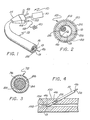
- a representative endoscope device 10 incorporates a fiberoptic 12 which comprises a single fiber hollow center light guide with a distal end 13.
- the fiberoptic 12 is coupled to a housing 14 which provides access to various parts of the fiberoptic structure 12.
- the fiberoptic 12 includes a fiber 16 which comprises a single unitary fiberoptic having a ring-shaped cross-section with a central channel 18 therethrough.
- the fiber 16 has an outer cylindrical surface 20 and an inner cylindrical surface 22.
- an outer cladding 24 is disposed to cover the outer cylindrical surface 20 and an inner cladding 26 is disposed to cover the inner cylindrical surface 22.
- the central channel 18 is hollow to enable access at the distal end 13 from the housing 14 through the central channel 18.
- illuminating light from an illuminator 40 enters a coupling light guide 42 which is attached to a illuminator port 44 in the housing 14.
- the housing 14 couples the light guide 42 to the fiber 16 of the fiberoptic 12 so that the light travels from the illuminator 40, through the coupling light guide 42, down the fiber 16 to the distal end 13 of the fiberoptic 12 to illuminate an object.
- the central channel 18 provides an access channel to the region adjacent the end 13 of the fiberoptic 12.
- a coherent fiber viewing bundle 28 is slidably positioned in the central channel 18 to permit viewing on the region adjacent to remote end 13 of the fiberoptic via a viewing system 50.
- the space between the inner bundle and interior surface of the central channel 18 could be used to deliver various solutions and medications into the body or provide a means of withdrawing tissue or fluid from inside a patient.
- the central channel 18 may itself be coupled to a central channel port 48 in the housing 14.
- the coherent fiber viewing bundle 28 may similarly be coupled to the viewing or laser system 50 via a viewing bundle port 52.
- the central channel 18 of the hollow fiberoptic 12 can be used to place the hollow fiberoptic 12 over flexible guide wire 46 which was previously inserted into the body of a subcutaneous manner, to accurately position the guide wire adjacent a selected intravascular structure of a human body. The hollow fiberoptic is then slid over the guide wire thereby allowing safe guidance of the fiberoptic inside the cardiovascular system of the subject with a minimum risk of vessel perforation.
- a fiberoptic system in accordance with the invention may include a flexible guide wire 46 for insertion into the biological subject 100 such as by subcutaneous insertion into the vascular system 102 of the biological subject 100 to a position adjacent a predefined location 104 inside the biological subject 100.
- the fiberoptic as heretofore described is slidingly positioned over the guide wire 46 and is advanced along the guide wire until the distal end 13 of the fiberoptic is adjacent to the predefined location.
- the guide wire can either remain in place or may be withdrawn as desired.
- a laser energy source 50 which may be incorporated as part of the system, is then interconnected to either the laser fiber 28 or the hollow fiberoptic itself to provide laser energy through the laser fiber or hollow fiberoptic to the predefined location so that laser energy may be precisely directed at the predefined location 104. It is emphasized that the laser fiber can be eliminated and the hollow fiberoptic itself used to transmit the laser energy to the predefined location 104.
- a laser system may be coupled to the coherent optical fiber bundle 28 (or, if desired a separate coherent optical fiber, or the hollow fiberoptic itself without the fiber bundle 28) and laser energy transported through the coherent optical fiber viewing bundle, or the fiberoptic itself, to the distal end 13 of the fiberoptic 12. Because the coherent bundle is in the center of the fiberoptic 12, or alternatively because the fiberoptic itself is used to transmit the laser energy, the laser energy can be precisely positioned and directed at a location adjacent the distal end. Further, the distal end can be accurately and precisely positioned by first sliding the fiberoptic over the guide wire previously positioned adjacent the desired location.
- the hollow fiberoptic in accordance with the invention can be utilized to permit sensor access to a region of the subject's body adjacent the end 13 of the fiberoptic 12.
- the central channel 18 of the hollow fiberoptic can be used to deliver various solutions and medications into the body while performing a diagnostic function such as sensing or a therapeutic function such as recanalization.
- the fiber 16, outer cladding 24 and inner cladding 26 are preferably made with plastic with selective refractive-indices which confine the light from the illuminator 40 in the fiber or light guide cylinder 16. Hence, light entering the end of the coupling light guide 42 adjacent the illuminator 40 will pass with minimum attenuation along the light guide cylinder 16 and will be delivered from the remote end 13 of the fiberoptic 12.
- Typical plastics which form the fiber, inner cladding and outer cladding may include methyl methacrylate; polystyrene for the fiber and lucite (polymethylmethacrylate) for the cladding; or a mixture of polystyrene and polymethyl methacrylate for the claddings.
- the light cylinder 16 is a single fiber, the necessity for a sheath is eliminated and the fiber 16 itself serves the dual function of being a light guide to transmit illuminating light energy to the remote end 13 of the fiberoptic 12 and a sheath to surrond the visualization bundle, and the like which are inserted through the central channel 18.
- the resultant fiberoptic 12 can therefore be made considerably smaller than fiberoptics requiring a sheath.
- the diameter of the fiberoptic 12 can be made as small as .75 mm or smaller thereby allowing the endoscope 10 to be utilized, particularly in cardiovascular applications, to view a significantly larger number of vessels.
- an outer protective jacket 32 may be disposed around the fiberoptic, particularly when the fiberoptic is made of glass, to protect the patient from injury should the fiberoptic break during use.
- the single fiber light guide 72 having a ring-shaped cross-section having a fiber 76, outer cladding 84 and inner cladding 86.
- the hollow fiberoptic 72 acts as a sheath with a coherent fiber viewing bundle 88 disposed in the center of the cylindrical light guide core 76 in a manner so that the fiber 76 is an integral part of the viewing bundle 88.
- Such a structure is made possible by filling the preform of the hollow fiberoptic with multiple solid fiberoptics arranged in a coherent manner to form the viewing bundle 88.
- the resulting assembly is then drawn through an oven so as to meld the viewing bundle and the surrounding single fiber light guide cylinder 76 together to form a structure which contains a plastic coherent bundle surrounded by a plastic fiberoptic sheath. It is noted that in order for such a structure to be made, it is presently necessary for both the viewing bundle 88 and the core 76 as well as the outer cladding 84 and the inner cladding 86 to be made of plastic. Such a structure will have certain favorable characteristics and will be able to be manufactured at substantially lower costs than conventional systems.
Landscapes
- Health & Medical Sciences (AREA)
- Life Sciences & Earth Sciences (AREA)
- Surgery (AREA)
- Physics & Mathematics (AREA)
- Optics & Photonics (AREA)
- Veterinary Medicine (AREA)
- Nuclear Medicine, Radiotherapy & Molecular Imaging (AREA)
- General Health & Medical Sciences (AREA)
- Public Health (AREA)
- Engineering & Computer Science (AREA)
- Biomedical Technology (AREA)
- Heart & Thoracic Surgery (AREA)
- Medical Informatics (AREA)
- Molecular Biology (AREA)
- Animal Behavior & Ethology (AREA)
- Pathology (AREA)
- Radiology & Medical Imaging (AREA)
- Biophysics (AREA)
- Vascular Medicine (AREA)
- Electromagnetism (AREA)
- Otolaryngology (AREA)
- Laser Surgery Devices (AREA)
- Endoscopes (AREA)
- Radiation-Therapy Devices (AREA)
Applications Claiming Priority (1)
| Application Number | Priority Date | Filing Date | Title |
|---|---|---|---|
| US06/752,757 US4768858A (en) | 1985-07-08 | 1985-07-08 | Hollow fiberoptic |
Publications (1)
| Publication Number | Publication Date |
|---|---|
| EP0338149A1 true EP0338149A1 (de) | 1989-10-25 |
Family
ID=25027709
Family Applications (1)
| Application Number | Title | Priority Date | Filing Date |
|---|---|---|---|
| EP88303497A Ceased EP0338149A1 (de) | 1985-07-08 | 1988-04-19 | Hohlrohrförmige Fiberoptik und -system |
Country Status (2)
| Country | Link |
|---|---|
| US (1) | US4768858A (de) |
| EP (1) | EP0338149A1 (de) |
Cited By (6)
| Publication number | Priority date | Publication date | Assignee | Title |
|---|---|---|---|---|
| EP0456015A1 (de) * | 1990-05-10 | 1991-11-13 | Schott Glaswerke | Distale Schutzkappe für einen Laser-Faser-Katheter |
| EP0512592A1 (de) * | 1991-05-06 | 1992-11-11 | Martin Uram M.D. | Laservideoendoskop |
| US5263928A (en) * | 1991-06-14 | 1993-11-23 | Baxter International Inc. | Catheter and endoscope assembly and method of use |
| FR2705242A1 (fr) * | 1993-05-13 | 1994-11-25 | Vidamed Inc | Dispositif à sonde médicale avec possibilité de vision optique. |
| US6999809B2 (en) | 2002-07-16 | 2006-02-14 | Edwards Lifesciences Corporation | Central venous catheter having a soft tip and fiber optics |
| US7029467B2 (en) | 2002-07-16 | 2006-04-18 | Edwards Lifesciences Corporation | Multiple lumen catheter having a soft tip |
Families Citing this family (48)
| Publication number | Priority date | Publication date | Assignee | Title |
|---|---|---|---|---|
| JPH01308522A (ja) * | 1988-06-06 | 1989-12-13 | Sumitomo Electric Ind Ltd | 診断治療用カテーテル |
| US5201317A (en) * | 1988-06-06 | 1993-04-13 | Sumitomo Electric Industries, Ltd. | Diagnostic and therapeutic catheter |
| EP0387753A1 (de) * | 1989-03-17 | 1990-09-19 | Schott Glaswerke | Verfahren und Vorrichtung zum Schutz der proximalen Einkoppelseiten von Laserkathetern |
| US4921326A (en) * | 1989-03-23 | 1990-05-01 | Victor F. Wild | Fiber optic probe |
| US5188634A (en) * | 1990-07-13 | 1993-02-23 | Trimedyne, Inc. | Rotatable laser probe with beveled tip |
| US5155788A (en) * | 1990-08-29 | 1992-10-13 | American Telephone & Telegraph Company | Optical fiber disposed in and decoupled from a reinforcing member |
| US5242438A (en) * | 1991-04-22 | 1993-09-07 | Trimedyne, Inc. | Method and apparatus for treating a body site with laterally directed laser radiation |
| US5190538A (en) * | 1991-04-22 | 1993-03-02 | Trimedyne, Inc. | Method and apparatus for subjecting a body site to a movable beam of laterally directed laser radiation |
| US5169395A (en) * | 1991-04-26 | 1992-12-08 | Pdt Cardiovascular, Inc. | Laser delivery system |
| US5250045A (en) * | 1991-06-11 | 1993-10-05 | The Spectranetics Corporation | Optical fiber catheter with spaced optical fiber |
| US5217456A (en) * | 1992-02-24 | 1993-06-08 | Pdt Cardiovascular, Inc. | Device and method for intra-vascular optical radial imaging |
| US5263952A (en) * | 1992-03-25 | 1993-11-23 | Spectranetics | Two-piece tip for fiber optic catheter |
| US5468239A (en) * | 1992-04-13 | 1995-11-21 | Sorenson Laboratories, Inc. | Apparatus and methods for using a circumferential light-emitting surgical laser probe |
| GB2268883A (en) * | 1992-07-23 | 1994-01-26 | Pennine Healthcare Limited | Endoscope |
| GB2269911B (en) * | 1992-08-17 | 1996-03-20 | Keymed | Light source connector with splayed optical fibre bundle |
| US5454807A (en) * | 1993-05-14 | 1995-10-03 | Boston Scientific Corporation | Medical treatment of deeply seated tissue using optical radiation |
| US5716320A (en) * | 1994-10-31 | 1998-02-10 | Buttermore; William J. | Illuminated intraocular surgical instrument |
| US5947958A (en) * | 1995-09-14 | 1999-09-07 | Conceptus, Inc. | Radiation-transmitting sheath and methods for its use |
| US6117128A (en) * | 1997-04-30 | 2000-09-12 | Kenton W. Gregory | Energy delivery catheter and method for the use thereof |
| US5964757A (en) * | 1997-09-05 | 1999-10-12 | Cordis Webster, Inc. | Steerable direct myocardial revascularization catheter |
| US6130976A (en) | 1998-04-15 | 2000-10-10 | 3M Innovative Properties Company | Coupling system for a light conduit |
| DE69809086T2 (de) * | 1998-04-15 | 2003-07-24 | Minnesota Mining & Manufacturing Company, St. Paul | Baugruppe für einen röhrenförmigen wellenleiter-beleuchtungssystem |
| US6290668B1 (en) | 1998-04-30 | 2001-09-18 | Kenton W. Gregory | Light delivery catheter and methods for the use thereof |
| US6478730B1 (en) * | 1998-09-09 | 2002-11-12 | Visionscope, Inc. | Zoom laparoscope |
| US20030207249A1 (en) * | 1999-04-15 | 2003-11-06 | Beske Oren E. | Connection of cells to substrates using association pairs |
| US20030129654A1 (en) * | 1999-04-15 | 2003-07-10 | Ilya Ravkin | Coded particles for multiplexed analysis of biological samples |
| US20040018485A1 (en) * | 1999-04-15 | 2004-01-29 | Ilya Ravkin | Multiplexed analysis of cells |
| US20030166015A1 (en) * | 1999-04-15 | 2003-09-04 | Zarowitz Michael A. | Multiplexed analysis of cell-substrate interactions |
| US20030134330A1 (en) * | 1999-04-15 | 2003-07-17 | Ilya Ravkin | Chemical-library composition and method |
| US6599237B1 (en) | 2000-01-10 | 2003-07-29 | Errol O. Singh | Instrument and method for facilitating endoscopic examination and surgical procedures |
| US6498941B1 (en) * | 2000-03-09 | 2002-12-24 | Advanced Cardiovascular Systems, Inc. | Catheter based probe and method of using same for detecting chemical analytes |
| DE10050648C2 (de) * | 2000-10-12 | 2003-11-06 | Fraunhofer Ges Forschung | Chirurgisches Instrument |
| JP2004537712A (ja) * | 2000-10-18 | 2004-12-16 | バーチャル・アレイズ・インコーポレーテッド | 多重細胞分析システム |
| GB2368659B (en) * | 2000-11-02 | 2004-01-21 | Keymed | An apparatus for providing an image of a remote object accessible only through an aperture of finite diameter |
| EP1637061A4 (de) * | 2003-05-01 | 2010-07-14 | Univ Keio | Intravaskuläres diagnose- oder therapiegerät mit hochintensitäts-pulslicht |
| WO2005028621A2 (en) * | 2003-09-15 | 2005-03-31 | Vitra Bioscience, Inc. | Assays with primary cells |
| US7488451B2 (en) * | 2003-09-15 | 2009-02-10 | Millipore Corporation | Systems for particle manipulation |
| DE102005013714A1 (de) * | 2004-04-07 | 2005-12-22 | Carl Zeiss Meditec Ag | Elektrische Sonde für die Mikrochirurgie |
| US20050277348A1 (en) * | 2004-06-09 | 2005-12-15 | Mark Antosh | Heat transfer material |
| US9005115B2 (en) | 2005-04-04 | 2015-04-14 | Invuity, Inc. | Illuminated telescoping cannula |
| US7469081B2 (en) * | 2006-09-01 | 2008-12-23 | Mobius Photonics, Inc. | Reducing thermal load on optical head |
| US20090318757A1 (en) * | 2008-06-23 | 2009-12-24 | Percuvision, Llc | Flexible visually directed medical intubation instrument and method |
| WO2010008793A1 (en) * | 2008-06-23 | 2010-01-21 | Percuvision, Llc | Flexible visually directed medical intubation instrument and method |
| US9629980B2 (en) * | 2010-11-24 | 2017-04-25 | Cook Medical Technologies Llc | Variable stiffness catheter, intraluminal treatment system, and method |
| DE102014118575B4 (de) * | 2014-12-12 | 2016-10-06 | Carl Zeiss Meditec Ag | Chirurgisches Instrument |
| KR20190049729A (ko) * | 2016-09-15 | 2019-05-09 | 아벤트, 인크. | 타겟화된 형광성 분자를 사용하는 신경의 정위치 시각화를 위한 시스템 및 방법 |
| EP4216888A1 (de) * | 2020-09-24 | 2023-08-02 | Alcon Inc. | Ergonomische sonde für kronleuchterendoilluminator |
| GB202204719D0 (en) * | 2022-03-31 | 2022-05-18 | Gowerlabs Ltd | Light guide module and apparatus for measuring changes in chromophore concentration |
Citations (8)
| Publication number | Priority date | Publication date | Assignee | Title |
|---|---|---|---|---|
| US3498286A (en) * | 1966-09-21 | 1970-03-03 | American Optical Corp | Catheters |
| US4253467A (en) * | 1979-11-02 | 1981-03-03 | Frazier Calvin H | Arthroscopic probe |
| EP0066120A2 (de) * | 1981-05-14 | 1982-12-08 | Olympus Optical Co., Ltd. | Endoskop |
| GB2108391A (en) * | 1981-10-29 | 1983-05-18 | Welch Allyn Inc | Speculum for medical instruments |
| DE8516415U1 (de) * | 1985-06-05 | 1985-09-19 | Richard Wolf Gmbh, 7134 Knittlingen | Führung für ein Uretero-Renoskop |
| DE3425427A1 (de) * | 1984-07-11 | 1986-01-16 | Olympus Winter & Ibe GmbH, 2000 Hamburg | Vorrichtung zur schaffung eines einfuehrungskanales fuer endoskope |
| US4583539A (en) * | 1982-01-12 | 1986-04-22 | Cornell Research Foundation, Inc. | Laser surgical system |
| FR2584199A1 (fr) * | 1985-06-26 | 1987-01-02 | Comp Generale Electricite | Fibre optique et application de cette fibre a un dispositif optique pour effectuer a distance l'analyse chimique d'un corps |
Family Cites Families (5)
| Publication number | Priority date | Publication date | Assignee | Title |
|---|---|---|---|---|
| US3261356A (en) * | 1963-10-21 | 1966-07-19 | American Cystoscope Makers Inc | Suction and illumination device |
| FR1394945A (fr) * | 1964-02-26 | 1965-04-09 | Comp Generale Electricite | Guide d'ondes à section circulaire pour la transmission d'ondes lumineuses ou infrarouges |
| US3583786A (en) * | 1969-09-23 | 1971-06-08 | Bell Telephone Labor Inc | Optical waveguide formed of cylinders with optically smooth interfaces therebetween |
| US4294234A (en) * | 1979-06-22 | 1981-10-13 | Olympus Optical Co., Ltd. | Endoscope |
| JPS597905A (ja) * | 1982-07-06 | 1984-01-17 | Sumitomo Electric Ind Ltd | 光フアイバの構造 |
-
1985
- 1985-07-08 US US06/752,757 patent/US4768858A/en not_active Expired - Fee Related
-
1988
- 1988-04-19 EP EP88303497A patent/EP0338149A1/de not_active Ceased
Patent Citations (8)
| Publication number | Priority date | Publication date | Assignee | Title |
|---|---|---|---|---|
| US3498286A (en) * | 1966-09-21 | 1970-03-03 | American Optical Corp | Catheters |
| US4253467A (en) * | 1979-11-02 | 1981-03-03 | Frazier Calvin H | Arthroscopic probe |
| EP0066120A2 (de) * | 1981-05-14 | 1982-12-08 | Olympus Optical Co., Ltd. | Endoskop |
| GB2108391A (en) * | 1981-10-29 | 1983-05-18 | Welch Allyn Inc | Speculum for medical instruments |
| US4583539A (en) * | 1982-01-12 | 1986-04-22 | Cornell Research Foundation, Inc. | Laser surgical system |
| DE3425427A1 (de) * | 1984-07-11 | 1986-01-16 | Olympus Winter & Ibe GmbH, 2000 Hamburg | Vorrichtung zur schaffung eines einfuehrungskanales fuer endoskope |
| DE8516415U1 (de) * | 1985-06-05 | 1985-09-19 | Richard Wolf Gmbh, 7134 Knittlingen | Führung für ein Uretero-Renoskop |
| FR2584199A1 (fr) * | 1985-06-26 | 1987-01-02 | Comp Generale Electricite | Fibre optique et application de cette fibre a un dispositif optique pour effectuer a distance l'analyse chimique d'un corps |
Non-Patent Citations (2)
| Title |
|---|
| PATENT ABSTRACTS OF JAPAN, Vol. 10, No. 173 (P-469)(2229), 18th June 1986; & JP,A,61 022 306 (SUMITOMO-DENKI) 30-01-1986. * |
| PATENT ABSTRACTS OF JAPAN, Vol. 10, No. 57 (P-434)(2114), 7th March 1986; & JP,A,60 200 203 (SUMITOMO DENKI) 09-10-1985. * |
Cited By (7)
| Publication number | Priority date | Publication date | Assignee | Title |
|---|---|---|---|---|
| EP0456015A1 (de) * | 1990-05-10 | 1991-11-13 | Schott Glaswerke | Distale Schutzkappe für einen Laser-Faser-Katheter |
| EP0512592A1 (de) * | 1991-05-06 | 1992-11-11 | Martin Uram M.D. | Laservideoendoskop |
| US5263928A (en) * | 1991-06-14 | 1993-11-23 | Baxter International Inc. | Catheter and endoscope assembly and method of use |
| FR2705242A1 (fr) * | 1993-05-13 | 1994-11-25 | Vidamed Inc | Dispositif à sonde médicale avec possibilité de vision optique. |
| EP0637436A1 (de) * | 1993-05-13 | 1995-02-08 | Vidamed, Inc. | Medizinische Sonde mit Einrichtung zur optischen Beobachtung |
| US6999809B2 (en) | 2002-07-16 | 2006-02-14 | Edwards Lifesciences Corporation | Central venous catheter having a soft tip and fiber optics |
| US7029467B2 (en) | 2002-07-16 | 2006-04-18 | Edwards Lifesciences Corporation | Multiple lumen catheter having a soft tip |
Also Published As
| Publication number | Publication date |
|---|---|
| US4768858A (en) | 1988-09-06 |
Similar Documents
| Publication | Publication Date | Title |
|---|---|---|
| US4768858A (en) | Hollow fiberoptic | |
| US5198894A (en) | Drape for endoscope | |
| US4718406A (en) | Fiber optics image scope (micro-endoscope), ureteroscope | |
| US8075478B2 (en) | System, apparatus, and method for viewing a visually obscured portion of a cavity | |
| US4921326A (en) | Fiber optic probe | |
| US5947958A (en) | Radiation-transmitting sheath and methods for its use | |
| EP0316244B1 (de) | Endoskop in Kanülenform mit Video-Einrichtung | |
| US4772093A (en) | Fiber-optic image-carrying device | |
| US5083549A (en) | Endoscope with tapered shaft | |
| US5159920A (en) | Scope and stent system | |
| US5116317A (en) | Angioplasty catheter with integral fiber optic assembly | |
| EP1478264B1 (de) | Miniaturendoskop mit bildgebendem fasersystem | |
| US4369768A (en) | Arthroscope | |
| EP0456761B1 (de) | Starres video-endoskop mit durch hitze sterilisierbarer umhüllung | |
| US3941121A (en) | Focusing fiber-optic needle endoscope | |
| US5872879A (en) | Rotatable connecting optical fibers | |
| EP0148034B1 (de) | Laser-Endoskop | |
| US5688224A (en) | Medical visualization device | |
| JPS6349125A (ja) | 内視鏡用案内管 | |
| WO2003051183A3 (en) | Sheath for guiding imaging instruments | |
| JPS61268245A (ja) | レ−ザ−・カテ−テル | |
| CA2143639A1 (en) | Sterilizable endoscope with separable disposable tube assembly | |
| JP2010519974A (ja) | 内視鏡用の先端面組立体 | |
| US5954652A (en) | Slipover illuminating ureteral catheter and method of installation | |
| CA1320890C (en) | Angioplasty catheter with integral fiber optic assembly |
Legal Events
| Date | Code | Title | Description |
|---|---|---|---|
| PUAI | Public reference made under article 153(3) epc to a published international application that has entered the european phase |
Free format text: ORIGINAL CODE: 0009012 |
|
| AK | Designated contracting states |
Kind code of ref document: A1 Designated state(s): CH DE ES FR GB IT LI NL SE |
|
| 17P | Request for examination filed |
Effective date: 19891204 |
|
| 17Q | First examination report despatched |
Effective date: 19910826 |
|
| STAA | Information on the status of an ep patent application or granted ep patent |
Free format text: STATUS: THE APPLICATION HAS BEEN REFUSED |
|
| 18R | Application refused |
Effective date: 19930727 |