EP0338248A1 - Dispositif pour la connexion de plusieurs organes (de machine), cette connexion assurant la transmission de couple - Google Patents
Dispositif pour la connexion de plusieurs organes (de machine), cette connexion assurant la transmission de couple Download PDFInfo
- Publication number
- EP0338248A1 EP0338248A1 EP89104612A EP89104612A EP0338248A1 EP 0338248 A1 EP0338248 A1 EP 0338248A1 EP 89104612 A EP89104612 A EP 89104612A EP 89104612 A EP89104612 A EP 89104612A EP 0338248 A1 EP0338248 A1 EP 0338248A1
- Authority
- EP
- European Patent Office
- Prior art keywords
- wrap spring
- shaft
- gear
- free
- wrap
- Prior art date
- Legal status (The legal status is an assumption and is not a legal conclusion. Google has not performed a legal analysis and makes no representation as to the accuracy of the status listed.)
- Withdrawn
Links
- 238000003801 milling Methods 0.000 claims abstract description 11
- 238000004804 winding Methods 0.000 claims description 25
- 230000005540 biological transmission Effects 0.000 claims description 11
- 230000007423 decrease Effects 0.000 claims description 5
- 230000003247 decreasing effect Effects 0.000 claims description 2
- 238000004519 manufacturing process Methods 0.000 description 4
- 230000015572 biosynthetic process Effects 0.000 description 2
- 238000011161 development Methods 0.000 description 2
- 230000018109 developmental process Effects 0.000 description 2
- 230000000694 effects Effects 0.000 description 2
- 230000008719 thickening Effects 0.000 description 2
- 238000010276 construction Methods 0.000 description 1
- 230000008878 coupling Effects 0.000 description 1
- 238000010168 coupling process Methods 0.000 description 1
- 238000005859 coupling reaction Methods 0.000 description 1
- 230000006378 damage Effects 0.000 description 1
- 239000013013 elastic material Substances 0.000 description 1
- 210000003746 feather Anatomy 0.000 description 1
- 238000000034 method Methods 0.000 description 1
- 230000036316 preload Effects 0.000 description 1
- 238000003825 pressing Methods 0.000 description 1
- 239000003380 propellant Substances 0.000 description 1
- 230000003313 weakening effect Effects 0.000 description 1
Images






Classifications
-
- F—MECHANICAL ENGINEERING; LIGHTING; HEATING; WEAPONS; BLASTING
- F16—ENGINEERING ELEMENTS AND UNITS; GENERAL MEASURES FOR PRODUCING AND MAINTAINING EFFECTIVE FUNCTIONING OF MACHINES OR INSTALLATIONS; THERMAL INSULATION IN GENERAL
- F16D—COUPLINGS FOR TRANSMITTING ROTATION; CLUTCHES; BRAKES
- F16D41/00—Freewheels or freewheel clutches
- F16D41/20—Freewheels or freewheel clutches with expandable or contractable clamping ring or band
- F16D41/206—Freewheels or freewheel clutches with expandable or contractable clamping ring or band having axially adjacent coils, e.g. helical wrap-springs
-
- F—MECHANICAL ENGINEERING; LIGHTING; HEATING; WEAPONS; BLASTING
- F16—ENGINEERING ELEMENTS AND UNITS; GENERAL MEASURES FOR PRODUCING AND MAINTAINING EFFECTIVE FUNCTIONING OF MACHINES OR INSTALLATIONS; THERMAL INSULATION IN GENERAL
- F16D—COUPLINGS FOR TRANSMITTING ROTATION; CLUTCHES; BRAKES
- F16D1/00—Couplings for rigidly connecting two coaxial shafts or other movable machine elements
- F16D1/06—Couplings for rigidly connecting two coaxial shafts or other movable machine elements for attachment of a member on a shaft or on a shaft-end
- F16D1/08—Couplings for rigidly connecting two coaxial shafts or other movable machine elements for attachment of a member on a shaft or on a shaft-end with clamping hub; with hub and longitudinal key
- F16D1/0829—Couplings for rigidly connecting two coaxial shafts or other movable machine elements for attachment of a member on a shaft or on a shaft-end with clamping hub; with hub and longitudinal key with radial loading of both hub and shaft by an intermediate ring or sleeve
Definitions
- the invention relates to a device for the torque-transmitting connection of several (machine) elements according to the preamble of claim 1.
- the invention is primarily concerned with the creation of a connection for transmitting a torque from a driven shaft to a pulley, a gearwheel, a clutch or the like seated thereon and vice versa, that is to say a so-called shaft-hub connection.
- the device according to the invention can also be used for clamping and driving a tool, namely a milling cutter or a drill, through a work spindle of a machine tool.
- the hub of a belt pulley, a gearwheel or the like is connected to a shaft in a form-fitting manner by means of feather keys or cross pins.
- the disadvantages of these connecting elements, in particular the weakenings caused thereby, are well known.
- the invention has for its object to further develop a device of the type mentioned in such a way that its tensioning element practically requires no additional space and is also both reliable and easy to manufacture.
- a device according to claim 1 solved.
- the design of the tensioning element as a wrap spring ensures that the torque to be transmitted is transmitted according to the rope friction principle.
- the elastic properties of the wrap spring it loops more and more tightly around the shaft or the tool as the load increases, whereby the friction between the wrap spring and the tool or the shaft also increases with increasing load.
- the power transmission capacity of this device thus increases approximately proportionally to the load, which, in contrast to known ring spring tensioning elements, does not require unnecessarily high preloads; rather, the bracing of the device with respect to the shaft or the tool adapts to the operating conditions.
- the tension member designed as a wrap spring of the device according to the invention has shock-absorbing effects due to its resilient properties. This largely compensates for load vibrations. Furthermore, the fact that the wrap spring first has to deform elastically before a correspondingly high torque can be transmitted has an advantageous effect in the device according to the invention. This ensures a short-term slippage, especially when pushing force (e.g. when starting off), which helps to reduce peak loads. In this way, for example, a start-up process is avoided more gently, but at the same time an overload of the device is effectively avoided.
- the loop spring expediently has several turns. As a result, particularly high torques can be transmitted, with the device being able to be dimensioned without problems by specifically selecting the number of turns.
- the wrap spring is one end of the wrap spring with a Driving flange of a gear, a pulley or the like. Connected, while the opposite end of the wrap spring is designed as a free end which is connected to the shaft or the tool.
- the free end of the wrap spring is preferably connected to the shaft or the tool in a form-fitting manner in that it is designed in the form of a tension ring. This allows easy assembly of the device by simply pushing it onto the shaft or inserting the tool into the wrap spring.
- a frictional bracing of the turn directed towards the free end of the wrap spring can optionally be dispensed with.
- a connecting element in particular a grub screw or the like, which serves for the positive connection of the wrap spring to the shaft, the tool or the like. At the same time, it can be designed as a shear pin.
- a wrap spring is integrally connected to the gear wheel, the toothed belt pulley, the drive flange or the like.
- the device according to the invention is thus an integral part of a machine element. This increases assembly simplified.
- the wrap spring or the wrap springs are designed such that they simultaneously form a hub of the machine element to be connected to the shaft or the like.
- the device according to the invention is characterized by particularly small external dimensions, that is to say a compact design.
- the individual windings are to be provided with a cross section which gradually decreases towards the free end of the wrap spring.
- the individual windings are adapted to the load occurring here, since, starting from the gearwheel, from the pulley or the like, the load decreases towards the free end of the wrap spring. This ensures uniform loading of the wrap spring across all turns, largely eliminating overloads and the resulting failures. It is also achieved by means of the winding passages provided with different cross sections that the surface pressure exerted on the shaft or the tool under load is approximately constant over the entire length of the wrap spring is.
- the pretensioning of the wrap spring required for frictional force transmission be made constant regardless of the load and in particular regardless of the load direction.
- the wrap spring is assigned a clamping member that rotates the two opposite end windings of the wrap spring against each other, in the direction of the winding, so that the diameter of the windings is reduced.
- 1 to 4 show a device that is not shown for the transmission of torque, in particular th shaft on a sprocket 20 or vice versa.
- the device has a single wrap spring 21 which is connected in one piece to the chain wheel 20.
- the wrap spring 21 is formed in the present exemplary embodiment from a cylindrical hub 22 which protrudes opposite one side of the chain wheel 20. Through a circumferential, helical groove 23 in the hub 22, the wrap spring 21 receives several turns 24. In the exemplary embodiment shown, the wrap spring 21 has four turns 24.
- the individual turns 24 have different cross sections, such that, starting from the sprocket 20, the cross sections of the turns 24 gradually decrease towards a free end 25 of the wrap spring 21, as can clearly be seen in FIG. 4.
- the helical groove 23 of the wrap spring 21 accordingly has a slope that continuously decreases toward the free end 25.
- the windings 24, viewed in cross section are rectangular, with a constant thickness running in the radial direction, but with decreasing width towards the free end 25 to the longitudinal direction of the wrap spring 21.
- the grooves 23 it is also conceivable to provide the grooves 23 not with a narrow rectangular cross section, but with a V-shaped cross section, as in the exemplary embodiment shown. In this case, the turns 24 have an approximately trapezoidal cross section.
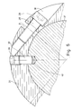
- the free end 25 of the wrap spring 21 is designed in a special way. As in particular FIGS. 1 and 3 he let know, namely the last turn 24 of the wrap spring 21 directed towards the free end 25 is formed as a clamping ring 26. For this purpose, a free turn end 27 of the last turn 24 is clamped to the previous turn 24 by a screw 28. For this purpose, this winding has a thickening 30 which receives a screw head 29 of the screw 28 and which ends at a distance from the free winding end 27 to form a gap 31 directed in the longitudinal direction of the wrap spring 21. By tightening the screw 28 and reducing the gap 31, the diameter of the clamping ring 26 can thus be reduced in order to clamp the free end 25 of the wrap spring 21 on the shaft, not shown.
- part of a turn 24 is formed by the body of the chain wheel 20 at an end of the wrap spring 21 opposite the free end 25 and connected to the chain wheel 20.
- a half-circular, continuous groove in the sprocket 20 in the present exemplary embodiment delimits the half turn 24 formed here with respect to the outer body of the sprocket 20.
- This part of the winding 24 can thus spring freely in the body of the chain wheel 20.
- the exit of the winding 24 from the chain wheel 20 is formed by a groove extension 33 which is directed radially at one end of the semicircular groove 32 (FIG. 2).
- FIG. 5 and 6 show a further embodiment the device in which a wrap spring 34 is integrally connected to a drive flange 35.
- the formation of the wrap spring 34 and the connection thereof with the drive flange 35 corresponds to the embodiment described above.
- the peculiarity of the wrap spring 34 is that it has a specially designed tension ring 36, which enables an (additional) positive connection of the wrap spring 34 to a shaft 37, which is indicated in FIG. 6.
- the tensioning ring 36 can be connected to the shaft 37 in such a way that that the cylinder shoulder 38 of the grub screw 39 projects radially directed into a corresponding blind hole 40 in the shaft 37.
- This allows on the one hand an exact positioning of the wrap spring 34 with the drive flange 35 with respect to the shaft 37, in particular in the axial direction of the shaft 37.
- the positive connection ensures that the wrap spring 34 does not slip with respect to the shaft 37 when starting.
- the grub screw 39 in particular the cylinder shoulder 38 on the same, the grub screw can have a shear pin function to avoid destruction when the device is overloaded.
- the screw 28 for the frictionally connected connection of the wrap spring 34 to the shaft 37 can be dispensed with as an alternative to the illustrated embodiment.
- the thickening 30 in the region of the winding 24 following the free winding end 27 is unnecessary.
- the wrap spring 34 is thereby more compact in its construction and also easier to manufacture.
- the exemplary embodiments of the device described above enable the transmission of a torque or the like in only one direction, namely in the winding direction.
- the windings 24 are elastically deformed by the driving force in the sense pressing against the shaft.
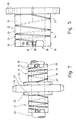
- FIG. 7 now shows a device with two wrap springs 41. As in the embodiment of FIGS. 5 and 6, these are each connected in one piece to a drive flange 42.
- the connection of the wrap springs 41 to the drive flanges 42 and the design of the individual wrap springs 41 again correspond to the exemplary embodiment in FIGS. 1 to 4.
- the two wrap springs 41 used here which are assigned in opposite directions to the opposite sides of the gear 44, ensure that, depending on the direction of rotation of the shaft 45, one of the two wrap springs 41 enables torque transmission from the shaft 45 to the gear 44 or vice versa. Depending on the direction of rotation of the shaft 45, one or the other wrap spring 41 thus alternatively creates a frictional connection to the respective drive flange 42 and thus to the gearwheel 44.
- the device shown here can thereby transmit a torque in both directions.
- FIGS. 8 and 9 show a front Direction for torque transmission between two shafts 46 and 47. Both devices have two wrap springs 48, each of which is integrally connected to a drive flange 49 at one end. In this respect, the devices shown in FIGS. 8 and 9 correspond to the device of FIG. 7.
- Each wrap spring 48 with its associated drive flange 49 is assigned to one of the opposite free shaft ends 50 and 51 of the two shafts 46 and 47 to be connected.
- the (smooth) end faces 52 of the drive flanges 49, which are directed away from the wrap springs 48, are again directed towards one another in such a way that they run parallel and at a distance from one another.
- the connecting piece 53 can consist of an elastic material.
- the device shown makes it possible to compensate for slight misalignments between the shaft ends 50 and 51, while at the same time eliminating drive-related vibrations before they are transmitted from the connecting piece 53 to the shaft 46 or 47 to be driven.
- FIG. 9 differs from that of FIG. 8 only in that the free ends 25 of the wrap springs 48 face each other, that is, they point to the respective shaft ends 50 and 51, respectively.
- a Connection with a correspondingly long connecting piece 54 is made here from the annular end faces 55 of the drive flanges 49 projecting towards the wrap springs 48.
- the special feature of the device of this exemplary embodiment is that the wrap springs 48 are located in the region of the connecting piece 54, that is to say they are surrounded by it and are therefore protected. Accordingly, the connecting piece 54 in FIG. 9 is correspondingly longer than the relatively short connecting piece 53 in FIG. 8.
- FIG. 10 shows a further use of the device, namely for clamping a milling cutter 56, which is shown here as an indication, in a milling head 57 of a corresponding machine tool.
- a wrap spring 58 is in turn connected in one piece to a corresponding drive flange 59.
- the wrap spring 58 and the drive flange 59 arranged thereon of this exemplary embodiment are in turn designed in a manner analogous to the exemplary embodiments of FIGS. 1 to 4 and 7 to 9 described above.
- the cutter 56 is here with its shaft from the driving flange 59 completely inserted into the wrap spring 58 and biased with a clamping ring 26.
- the drive flange 59 is screwed in the area of its annular end face 60 with a (lower) end face 61 to an annular milling spindle 62 of the milling head 57.
- the wrap spring 58 lies protected inside the (hollow) milling spindle 62.
- the device can also be used for clamping other tools, for example a drill, a reamer, etc.
- the device is also not limited to connecting a sprocket 20 or a gear 44 to a corresponding shaft; rather, flat belt pulleys, V-belt pulleys, coupling parts etc. can also be connected to a shaft in a corresponding manner.
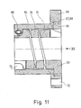
- the exemplary embodiment of the device shown in FIGS. 11 to 13 has a wrap spring 63 which is suitable for transmitting a drive torque in opposite directions in an almost slip-free manner.
- the wrap spring 63 is elastically clamped by a clamping member assigned to it, namely a clamping sleeve 64.
- the windings 24 are designed as in the (first) exemplary embodiment described above.
- the drive flange 65 is also connected in one piece to the wrap spring 63, the first half turn 24 of the wrap spring 63 being integrated into the drive flange 65 by a semicircular groove 32 in the drive flange 65, which is the first half turn 24 of the wrap spring, as shown in FIG. 13 63 demarcated from propellant bottle 65.
- the clamping sleeve 64 completely surrounds all turns 24 of the wrap spring 63, for which purpose the clamping sleeve 64 extends approximately over the length of the entire wrap spring 63.
- the opposite ends of the wrap spring 63 namely a drive flange 65 shown on the right in FIG. 11 and the opposite Gende free front turn 66 are locked by the clamping ring 64 in a non-rotatable relative position to each other.
- the driving flange 65 is therefore not used to directly receive a gear wheel to be driven, etc., but rather to establish a positive connection to the clamping sleeve 64.
- This positive locking of the drive flange 65 on the clamping sleeve 64 takes place by means of a plurality of elevations 67 which are distributed uniformly around the circumference of the driving flange 65 and which engage in corresponding recesses 68 of a flange 69 at the corresponding end of the clamping sleeve 64.
- the positive connection can also be formed by other connecting elements of the usual type, for example a toothing or a polygonal profile.
- the flange 69 serves to fasten a chain wheel, gearwheel or the like (not shown).
- the flange 69 has a plurality of through bores 70 which are arranged at a uniform spacing around the circumference thereof.
- the free end 71 of the clamping sleeve 64 opposite the flange 69 is also positively connected to the free end turn 66 of the wrap spring 63.
- This positive connection is designed according to the invention in such a manner that the free end turn 66 can be rotated in the direction of the turn relative to the driving flange 65 of the wrap spring 63, whereby the wrap spring 63 with the other turns 24 is firmly attached to a component (not shown) which carries the wrap spring 63, in particular a component Shaft or the like, can be pressed to transmit a corresponding torque in the opposite direction.
- the free end 71 of the clamping sleeve 64 is provided with radial recesses 72 evenly distributed on the circumference for prestressing the free end turn 66.
- the recesses 72 are also radial thread passage bores 73 provided, in the clamping screws 75 can be screwed.
- the free end turn 66 of the wrap spring 63 is formed corresponding to the recesses 72 in the free end 71 of the clamping sleeve 64.
- This consequently has wing-like cams 74 which engage in the recesses 72 of the clamping sleeve 64 in such a way that they are to a certain extent together with the free one.
- End wall 66 of the wrap spring 63 can be rotated in the free end 71 of the clamping sleeve 64 for pretensioning the wrap spring 63.
- the free end turn 66 of the wrap spring 63 is rotated by the screws 75 inserted into the threaded bores 73 of the free end 71, of which a screw 75 is indicated in FIG. 12.
- the screws 75 are supported with their end faces 76 on the cams 74, specifically on corresponding stop faces 77 thereof.
Landscapes
- Engineering & Computer Science (AREA)
- General Engineering & Computer Science (AREA)
- Mechanical Engineering (AREA)
- Gears, Cams (AREA)
Applications Claiming Priority (4)
| Application Number | Priority Date | Filing Date | Title |
|---|---|---|---|
| DE3809027 | 1988-03-17 | ||
| DE3809027 | 1988-03-17 | ||
| DE3820189 | 1988-06-14 | ||
| DE3820189A DE3820189A1 (de) | 1988-03-17 | 1988-06-14 | Vorrichtung zur drehmomentuebertragenden verbindung mehrerer (maschinen-)elemente |
Publications (1)
| Publication Number | Publication Date |
|---|---|
| EP0338248A1 true EP0338248A1 (fr) | 1989-10-25 |
Family
ID=25866072
Family Applications (1)
| Application Number | Title | Priority Date | Filing Date |
|---|---|---|---|
| EP89104612A Withdrawn EP0338248A1 (fr) | 1988-03-17 | 1989-03-15 | Dispositif pour la connexion de plusieurs organes (de machine), cette connexion assurant la transmission de couple |
Country Status (3)
| Country | Link |
|---|---|
| US (1) | US4934990A (fr) |
| EP (1) | EP0338248A1 (fr) |
| DE (1) | DE3820189A1 (fr) |
Cited By (3)
| Publication number | Priority date | Publication date | Assignee | Title |
|---|---|---|---|---|
| EP0511362A4 (en) * | 1990-11-14 | 1993-05-05 | General Clutch Corporation | Friction hinge assembly |
| DE102014017430A1 (de) * | 2014-11-25 | 2016-05-25 | Wabco Europe Bvba | Scheibenbremse, insbesondere für Nutzfahrzeuge |
| DE102014017438A1 (de) * | 2014-11-25 | 2016-05-25 | Wabco Europe Bvba | Scheibenbremse. insbesondere für Nutzfahrzeuge |
Families Citing this family (11)
| Publication number | Priority date | Publication date | Assignee | Title |
|---|---|---|---|---|
| US5413265A (en) * | 1990-07-07 | 1995-05-09 | Agfa-Gevaert A.G. | Arrangement for transporting web-shaped materials to be scanned or exposed |
| DE4128795A1 (de) * | 1991-08-27 | 1993-03-04 | Geraetewerk Babelsberg Gmbh | Einrichtung zur gedaempften uebertragung der drehbewegung bei ovalradzaehlern |
| US5468188A (en) * | 1992-10-02 | 1995-11-21 | Day; Stanley J. | Universal coupling |
| US5819146A (en) * | 1997-03-07 | 1998-10-06 | Roderick; Sheldon Lee | Magnetic brush roller having a wire-wound floating hub |
| DE19728241C2 (de) * | 1997-07-02 | 1999-11-25 | Mannesmann Sachs Ag | Torsionsschwingungsdämpfer |
| DE19907181B4 (de) * | 1999-02-19 | 2004-02-19 | Neugart Gmbh & Co. | Verbindung einer geschlitzten Hohlwelle, Hohlachse oder Hülse mit einem eingreifenden Gegenstück |
| DE10206168A1 (de) | 2002-02-14 | 2003-08-21 | Guehring Joerg | Kupplung für mudular aufgebaute Werkzeughalterarme |
| DE102005055034B3 (de) * | 2005-09-01 | 2007-02-08 | Muhr Und Bender Kg | Torisionsschwingungsdämpfer oder Dekoppler mit gewickelten Drahtfedern in einer Antriebsscheibe |
| US9334016B2 (en) * | 2012-07-13 | 2016-05-10 | Shimano Inc. | Bicycle rear derailleur |
| US20180266454A1 (en) * | 2017-03-14 | 2018-09-20 | MISUMI USA, Inc. | Clamping Hub |
| USD1022683S1 (en) | 2021-03-15 | 2024-04-16 | Designatronics, Inc. | Coupling device |
Citations (12)
| Publication number | Priority date | Publication date | Assignee | Title |
|---|---|---|---|---|
| DE129801C (fr) * | ||||
| US1392363A (en) * | 1920-01-24 | 1921-10-04 | Edwing P Shannon | Clamping means for rotary members |
| FR750068A (fr) * | 1932-04-26 | 1933-08-03 | Malicet Et Blin Ets | Perfectionnements aux mécanismes utilisant l'adhérence, pour toutes applications |
| US2175473A (en) * | 1938-05-02 | 1939-10-10 | Landrum Porter | Power transmission |
| US2574714A (en) * | 1948-12-03 | 1951-11-13 | Maytag Co | Method of forming a flexible coil clutch |
| US2638365A (en) * | 1949-08-04 | 1953-05-12 | John A Jones | Coupling |
| FR1148387A (fr) * | 1955-05-28 | 1957-12-06 | Auto Union Gmbh | Dispositif de roue libre |
| US3125889A (en) * | 1964-03-24 | Spring clutch and control means | ||
| DE1525340A1 (de) * | 1965-01-28 | 1969-12-18 | Curtiss Wright Corp | Federbandreibungskupplung |
| GB1476443A (en) * | 1974-10-21 | 1977-06-16 | Ming Chao Chang | Device for gripping a rod-shaped object such as the shank of a screwdriver tap or other tool |
| DE3219483A1 (de) * | 1982-05-25 | 1983-12-08 | Agfa-Gevaert Ag, 5090 Leverkusen | Kupplung zum herstellen einer drehfesten verbindung |
| FR2568335A1 (fr) * | 1984-07-30 | 1986-01-31 | Declic System Sarl | Dispositif de blocage unidirectionnel en rotation |
Family Cites Families (5)
| Publication number | Priority date | Publication date | Assignee | Title |
|---|---|---|---|---|
| US1471488A (en) * | 1920-06-23 | 1923-10-23 | Charles J Deckop | Cushion shaft coupling |
| US2680383A (en) * | 1950-08-14 | 1954-06-08 | Cons Eng Corp | Rotatable control |
| US3139296A (en) * | 1962-04-09 | 1964-06-30 | Sanford I Greene | Clampable precision gear |
| US3307418A (en) * | 1965-02-26 | 1967-03-07 | Fairchild Camera Instr Co | Clampable precision hub |
| US3572197A (en) * | 1968-12-10 | 1971-03-23 | Devlieg Machine Co | Adjustable toolholder |
-
1988
- 1988-06-14 DE DE3820189A patent/DE3820189A1/de not_active Withdrawn
-
1989
- 1989-03-15 EP EP89104612A patent/EP0338248A1/fr not_active Withdrawn
- 1989-03-15 US US07/324,404 patent/US4934990A/en not_active Expired - Fee Related
Patent Citations (12)
| Publication number | Priority date | Publication date | Assignee | Title |
|---|---|---|---|---|
| DE129801C (fr) * | ||||
| US3125889A (en) * | 1964-03-24 | Spring clutch and control means | ||
| US1392363A (en) * | 1920-01-24 | 1921-10-04 | Edwing P Shannon | Clamping means for rotary members |
| FR750068A (fr) * | 1932-04-26 | 1933-08-03 | Malicet Et Blin Ets | Perfectionnements aux mécanismes utilisant l'adhérence, pour toutes applications |
| US2175473A (en) * | 1938-05-02 | 1939-10-10 | Landrum Porter | Power transmission |
| US2574714A (en) * | 1948-12-03 | 1951-11-13 | Maytag Co | Method of forming a flexible coil clutch |
| US2638365A (en) * | 1949-08-04 | 1953-05-12 | John A Jones | Coupling |
| FR1148387A (fr) * | 1955-05-28 | 1957-12-06 | Auto Union Gmbh | Dispositif de roue libre |
| DE1525340A1 (de) * | 1965-01-28 | 1969-12-18 | Curtiss Wright Corp | Federbandreibungskupplung |
| GB1476443A (en) * | 1974-10-21 | 1977-06-16 | Ming Chao Chang | Device for gripping a rod-shaped object such as the shank of a screwdriver tap or other tool |
| DE3219483A1 (de) * | 1982-05-25 | 1983-12-08 | Agfa-Gevaert Ag, 5090 Leverkusen | Kupplung zum herstellen einer drehfesten verbindung |
| FR2568335A1 (fr) * | 1984-07-30 | 1986-01-31 | Declic System Sarl | Dispositif de blocage unidirectionnel en rotation |
Cited By (5)
| Publication number | Priority date | Publication date | Assignee | Title |
|---|---|---|---|---|
| EP0511362A4 (en) * | 1990-11-14 | 1993-05-05 | General Clutch Corporation | Friction hinge assembly |
| DE102014017430A1 (de) * | 2014-11-25 | 2016-05-25 | Wabco Europe Bvba | Scheibenbremse, insbesondere für Nutzfahrzeuge |
| DE102014017438A1 (de) * | 2014-11-25 | 2016-05-25 | Wabco Europe Bvba | Scheibenbremse. insbesondere für Nutzfahrzeuge |
| US10221908B2 (en) | 2014-11-25 | 2019-03-05 | Wabco Europe Bvba | Disc brake with adjustment mechanism having a thread device |
| US10670097B2 (en) | 2014-11-25 | 2020-06-02 | Wabco Europe Bvba | Disc brake with adjustment mechanism having a thread device |
Also Published As
| Publication number | Publication date |
|---|---|
| US4934990A (en) | 1990-06-19 |
| DE3820189A1 (de) | 1989-09-28 |
Similar Documents
| Publication | Publication Date | Title |
|---|---|---|
| EP0354363B1 (fr) | Dispositif de blocage à douille taraudée | |
| EP1307313B1 (fr) | Machine portable | |
| EP0565543B1 (fr) | Element d'accouplement pour l'assemblage par liaison de force d'un element exterieur avec un arbre | |
| DE10053183A1 (de) | Vorrichtung für die automatische Kontrolle des Abstands zwischen Getrieben | |
| EP0338248A1 (fr) | Dispositif pour la connexion de plusieurs organes (de machine), cette connexion assurant la transmission de couple | |
| EP3472492B1 (fr) | Transmission à train épicycloïdal | |
| DE102008005229B4 (de) | Antriebseinrichtung | |
| EP2805078B1 (fr) | Accouplement d'arbre et moyeu, adaptateur et moteur d'entrainement | |
| EP0208979B1 (fr) | Sécurité contre la surcharge | |
| DE102015115001B4 (de) | Riemenscheiben-Baugruppe | |
| DE60205878T2 (de) | Brems-kupplung anordnung | |
| EP2144838B1 (fr) | Treuil | |
| DE2530052A1 (de) | Kupplung zum drehfesten verbinden einander zugeordneter abschnitte einer lieferwelle fuer textilmaschinen | |
| EP0840021A1 (fr) | Dispositif pour la connexion d'éléments de montage | |
| DE1425359B2 (de) | Nabenbefestigung | |
| DE3500324C2 (de) | Drehmomentbegrenzungseinrichtung | |
| EP0604887B1 (fr) | Embrayage à glissement réglable | |
| DE3202420A1 (de) | Schrauber, vorzugsweise druckluftschrauber | |
| DE3938445C1 (en) | Simple taper-lock bush assembly - incorporates equally spaced axial tension screws protruding through end flange on inner taper bush | |
| DE102010037357B4 (de) | Mechanisches Verbindungselement | |
| DE69002240T2 (de) | Gewindebuchseneinheit fuer monatge auf einer welle. | |
| DE3532727C1 (de) | Rollenförderer | |
| DE10344869B3 (de) | Sicherheitskupplung | |
| AT503331B1 (de) | Getriebe | |
| DE3613868C2 (fr) |
Legal Events
| Date | Code | Title | Description |
|---|---|---|---|
| PUAI | Public reference made under article 153(3) epc to a published international application that has entered the european phase |
Free format text: ORIGINAL CODE: 0009012 |
|
| AK | Designated contracting states |
Kind code of ref document: A1 Designated state(s): DE ES FR GB IT NL SE |
|
| 17P | Request for examination filed |
Effective date: 19891204 |
|
| 17Q | First examination report despatched |
Effective date: 19910524 |
|
| STAA | Information on the status of an ep patent application or granted ep patent |
Free format text: STATUS: THE APPLICATION IS DEEMED TO BE WITHDRAWN |
|
| 18D | Application deemed to be withdrawn |
Effective date: 19921001 |