EP0604887B1 - Embrayage à glissement réglable - Google Patents
Embrayage à glissement réglable Download PDFInfo
- Publication number
- EP0604887B1 EP0604887B1 EP93120640A EP93120640A EP0604887B1 EP 0604887 B1 EP0604887 B1 EP 0604887B1 EP 93120640 A EP93120640 A EP 93120640A EP 93120640 A EP93120640 A EP 93120640A EP 0604887 B1 EP0604887 B1 EP 0604887B1
- Authority
- EP
- European Patent Office
- Prior art keywords
- shaft
- sliding clutch
- clutch according
- wedge members
- wedge
- Prior art date
- Legal status (The legal status is an assumption and is not a legal conclusion. Google has not performed a legal analysis and makes no representation as to the accuracy of the status listed.)
- Expired - Lifetime
Links
- 230000008878 coupling Effects 0.000 abstract description 22
- 238000010168 coupling process Methods 0.000 abstract description 22
- 238000005859 coupling reaction Methods 0.000 abstract description 22
- 230000006835 compression Effects 0.000 abstract description 10
- 238000007906 compression Methods 0.000 abstract description 10
- 230000005540 biological transmission Effects 0.000 description 9
- 238000006073 displacement reaction Methods 0.000 description 3
- 238000004519 manufacturing process Methods 0.000 description 2
- 230000000694 effects Effects 0.000 description 1
- 238000000034 method Methods 0.000 description 1
- 230000000284 resting effect Effects 0.000 description 1
Images
Classifications
-
- F—MECHANICAL ENGINEERING; LIGHTING; HEATING; WEAPONS; BLASTING
- F16—ENGINEERING ELEMENTS AND UNITS; GENERAL MEASURES FOR PRODUCING AND MAINTAINING EFFECTIVE FUNCTIONING OF MACHINES OR INSTALLATIONS; THERMAL INSULATION IN GENERAL
- F16D—COUPLINGS FOR TRANSMITTING ROTATION; CLUTCHES; BRAKES
- F16D7/00—Slip couplings, e.g. slipping on overload, for absorbing shock
- F16D7/02—Slip couplings, e.g. slipping on overload, for absorbing shock of the friction type
- F16D7/024—Slip couplings, e.g. slipping on overload, for absorbing shock of the friction type with axially applied torque limiting friction surfaces
- F16D7/025—Slip couplings, e.g. slipping on overload, for absorbing shock of the friction type with axially applied torque limiting friction surfaces with flat clutching surfaces, e.g. discs
Definitions
- the invention relates to an adjustable, coaxially arranged to a shaft slip clutch with friction disks, at least one of which is spring-loaded by a compression spring assembly, which is supported on a pressure piece that is movable coaxially to the shaft for adjusting the coupling force.
- Such slipping clutches are known from practice and serve, for example, as a safety clutch between the drive motor and the gearbox of a work machine.
- the known slip clutches have one or more friction disks, via which the drive torque of the motor is transmitted to the drive shaft of the transmission.
- at least one of the outer friction disks of the clutch is pressurized by means of compression springs in such a way that a non-positive connection is established between the output shaft of the motor and the drive shaft of the transmission.
- the contact pressure of the springs is set so that the clutch slips if the load is too high or the transmission is blocked.
- Slip clutches of this type show wear after a certain operating time, which is caused by an unavoidable slip when starting the machine or during machine use. The result is a reduction in pressure. It is therefore necessary to readjust the pressure force of the springs at specified time intervals.
- an electromagnetic brake is known from German published patent application DE-OS 27 47 466, in which friction linings are fastened to a rotatably but axially movably arranged housing in which electromagnets are accommodated.
- an armature disk connected to a drive shaft in a rotationally fixed manner, but axially displaceable thereon, is pulled against the friction linings, so that the drive shaft is braked.
- the housing with the friction linings can be moved toward the armature disk axially parallel to the drive shaft by means of a set screw.
- This set screw has a tapered tip which is in contact with the housing and is aligned at right angles to the drive shaft through a housing surrounding the entire coupling, so that a radial feed of the set screw causes the axially parallel displacement of the housing with the friction linings.
- the advantage of this device is that the brake can be adjusted from outside the housing. For this, however, it is necessary that the actual braking element is arranged in a rotationally fixed manner and the braking force is applied by an electromagnet.
- the adjusting device implemented in the known electromagnetic brake is therefore unsuitable for adjusting such slip clutches which are connected in a rotationally fixed manner to the respective shafts.
- a sliding clutch is known from Swiss patent CH-PS 489 724, in which the friction linings are pressed against the coupling halves assigned to them by means of a wedge piece.
- the cone piece is permanently spring-loaded by the force of a spring ring, so that any wear of the clutch linings is compensated for by a radial feed movement of the wedge piece and an associated axial movement of the friction linings.
- the advantage of the known device is that the wear of the friction linings is automatically compensated.
- this coupling is not suitable for the transmission of larger forces.
- the object of the invention is to improve a slip clutch of the type mentioned with simple means in such a way that the spring travel of the compression spring can be easily adjusted with increased accuracy.
- the pressure piece is displaceable by radially adjustable wedge pieces which are supported on at least one coaxial to the shaft and connected to the support ring and are adjustable by a common actuator.
- the springs are no longer adjusted via an adjusting nut seated on the shaft, but via wedge pieces which can be advanced in the radial direction or moved away from the latter.
- the wedge surfaces of the wedge pieces deflect the radial feed movement of the wedge pieces into an axially parallel displacement movement of the pressure piece, by means of which the compression springs are adjusted.
- the accuracy of this readjustment movement can be preselected by an appropriate choice of the wedge angle in connection with the feed of the actuator.
- the adjustment of the wedge pieces is easily possible because they are moved together by the actuator, which acts on all wedge pieces to the same extent. Since the adjusting nut is no longer required for readjusting the compression springs, there is no need for an expensive fine thread on the shaft.
- An easy to manufacture and proven in practical testing slip clutch is characterized in that the wedge pieces are arranged in pairs opposite to each other on the shaft and the common actuator is formed by a rotatable threaded rod, which is inserted through a transverse bore of the shaft and the sections thereof have opposite threads, which engage in corresponding threaded holes in the wedge pieces. If the threaded rod is also formed on at least one of its ends on the end face as an engagement head for a tool for rotating the threaded rod, the compression springs can be readjusted with the aid of a tool with particularly small dimensions. Such an embodiment of the invention is particularly advantageous when the slip clutch rotates in a closed housing and there is only a closable opening of small diameter for inserting the tool into the housing.
- the common actuator is formed by a clamping band resting on the wedge pieces.
- This embodiment of the invention makes it possible to design the wedge pieces as circular segments and to arrange them around the circumference of the shaft. In this way, tilting of the second pressure piece on the shaft can be reliably avoided and a uniform force effect of the pressure spring package on the slip clutch can be achieved.
- the adjustability of the coupling can be further facilitated in that the surface of the support ring assigned to the wedge pieces is designed as a wedge surface.
- a second pressure piece can be arranged between the support ring and the wedge pieces, the surface of which is assigned to the wedge pieces and is designed as a wedge surface. This embodiment is particularly easy to implement if the second pressure piece is formed by a plate spring.
- the assembly of the slip clutch according to the invention can be simplified in that the support ring is formed by an adjusting nut which can be screwed onto an external thread of the shaft.
- a rough presetting of the coupling force can be carried out by turning the adjusting nut when assembling the coupling.
- a coarse thread that can be produced inexpensively is sufficient, since the pressure force can be adjusted with the required accuracy in the fully assembled coupling by adjusting the wedge pieces according to the invention.
- the axial movement of the springs caused by this when the wedge pieces are displaced can be increased in that the wedge pieces are designed as double wedges.
- the area of the first pressure piece assigned to the wedge pieces should also be designed as a wedge area.
- transverse bore is designed as an elongated hole, the opening of which extends axially parallel to the shaft.
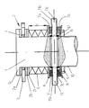
- the drawing shows a shaft 1 rotating in an oil bath in a closed gearbox housing, not shown, with a slip clutch 2 arranged at its end and having friction linings 2a, b arranged coaxially with the shaft 1.
- the first friction lining 2a is connected in a rotationally fixed manner to a shaft shoulder 1a of the shaft 1, while the second friction lining 2b is fastened to a first friction disk 2c which can be displaced coaxially to the shaft 1.
- a ring gear 3 is also inserted coaxially to the shaft 1, which is arranged on a race 4 seated on the shaft 1 and is in engagement with the output shaft of a drive motor, not shown.
- the friction disc 2c is loaded by the spring force of a disc spring assembly 5 formed from six disc springs, which is arranged coaxially to the shaft 1 and is clamped between the friction disc 2c and a perforated disc-shaped, also coaxial to the shaft 1, the first pressure piece 6.
- the pressure piece 6 is supported with its lower side on the upper side 7a, which extends at right angles to the shaft 1, of two wedge pieces 7 arranged opposite one another on both sides of the shaft 1.
- the wedge pieces 7 are in turn supported on their wedge-shaped underside 7b via a plate spring 8 acting as a second pressure piece on an adjusting nut 10 which is screwed onto an external thread 9 formed on the outside of the shaft 1 in a self-locking manner.
- a threaded rod 11 is provided, which is inserted into a transverse bore 1b of the shaft 1 which is designed as an elongated hole.
- opposing external threads 11a, b are formed, which cooperate with the threads of threaded bores 7c of the wedge pieces 7 and are designed to be self-locking.
- the threaded rod 11 is formed at one end as an attack head of a tool, in that it has notches 11c on the end face, into which the blade of a screwdriver can be plugged for rotating the threaded rod 11.
- the threaded rod 11 is secured by circlips 12 in the transverse bore 1b.
- presetting of the pressure force acting on the slip clutch 2 through the spring assembly 5 is carried out by screwing the adjusting screw 9 onto the thread 10.
- the threaded rod 11 is axially displaceable within the transverse bore 1b designed as an elongated hole, so that the wedge pieces 7, the plate spring 8 and the pressure pieces 6 are displaced axially parallel to the shaft 1 when the adjusting nut 9 is rotated.
- the basic setting of the slip clutch 2 can be varied within a wide range.
- the shaft 1 is rotated until a screwdriver can be inserted into the notch 11c through an opening in the transmission housing. Then the shaft 1 is secured against further rotation and the threaded rod 11 is rotated by means of the screwdriver. As a result of the rotation of the threaded rod 11, the wedge pieces 7 are moved towards one another radially to the shaft 1 due to the counter-rotation of the threaded sections 11a, b. The wedge pieces 7 slide with their bevelled underside 7b on the plate spring 8, so that the radial feed movement of the wedge pieces 7 is converted into an axial movement of the pressure piece 6. The spring travel f of the spring assembly 5 is further reduced by this movement.
- the threaded rod 11 is also shifted axially parallel to the shaft 1 within the transverse bore 1b by the same amount. In this way, the pressure force exerted by the plate spring assembly 5 on the slip clutch 2 is increased, so that after adjusting the slip clutch 2 a sufficient clutch force for transmitting the drive torque to the transmission is again ensured.
Landscapes
- Engineering & Computer Science (AREA)
- General Engineering & Computer Science (AREA)
- Mechanical Engineering (AREA)
- Braking Arrangements (AREA)
- Mechanical Operated Clutches (AREA)
- One-Way And Automatic Clutches, And Combinations Of Different Clutches (AREA)
Claims (9)
- Dispositif d'accouplement (2) à friction pouvant être réajusté et disposé coaxialement par rapport à un arbre (1), comprenant des disques de friction (2c) dont au moins un est mis sous contrainte au moyen d'un bloc (5) de ressorts de pression, bloc qui est supporté par une pièce (6) de pression mobile coaxialement par rapport à l'arbre (1) pour l'ajustement de la force d'accouplement, caractérisé en ce que la pièce (6) de pression peut coulisser par l'intermédiaire de pièces (7) de coin réglables radialement par rapport à l'arbre (1), pièces qui sont supportées par au moins un anneau (9) de support disposé coaxialement par rapport à l'arbre (1) et relié à celui-ci, et qui peuvent être réglées au moyen d'un vérin (11) commun.
- Dispositif d'accouplement à friction selon la revendication 1, caractérisé en ce que les pièces (7) de coin sont agencées par paires, respectivement diamétralement opposées l'une de l'autre, sur l'arbre (1) et le vérin commun est formé par respectivement une tige filetée (11) pouvant être tournée, tige filetée qui traverse un perçage transversal de l'arbre (1) et qui comporte dans ses zones d'extrémité respectivement des filetages (11a, b) à contre sens qui sont en prise avec des perçages (7c) filetés correspondant des pièces (7) de coin.
- Dispositif d'accouplement à friction selon la revendication 2, caractérisé en ce que la tige filetée (11) est réalisée, au moins à une de ses extrémités, avec une tête d'entraînement (11c) pour un outil pour tourner la tige filetée (11).
- Dispositif d'accouplement à friction selon la revendication 1, caractérisé en ce que le vérin commun est formé par un collier de fixation, en contact avec les pièces (7) de coin.
- Dispositif d'accouplement selon l'une quelconque des revendications précédentes, caractérisé en ce que la surface de l'anneau de support (9) associée aux pièces (7) de coin est réalisée sous la forme d'une surface de coin.
- Dispositif d'accouplement à friction selon l'une quelconque des revendications précédentes, caractérisé en ce qu'une seconde pièce de pression est disposée entre l'anneau de support (9) et les pièces (7) de coin, dont la surface associée aux pièces (7) de coin est réalisée sous la forme d'une surface de coin.
- Dispositif d'accouplement à friction selon la revendication 6, caractérisé en ce que la deuxième pièce de pression est réalisée sous la forme d'une rondelle ressort (8).
- Dispositif d'accouplement à friction selon l'une quelconque des revendications précédentes, caractérisé en ce que l'anneau de support (9) est formé par un écrou de réglage qui peut être vissé sur le filetage extérieur (10) de l'arbre (1).
- Dispositif d'accouplement à friction selon l'une quelconque des revendications précédentes, caractérisé en ce que le perçage transversal (1c) est réalisé comme trou oblong dont l'ouverture s'étend parallèlement à l'axe de l'arbre (1).
Applications Claiming Priority (2)
| Application Number | Priority Date | Filing Date | Title |
|---|---|---|---|
| DE4244501A DE4244501C1 (de) | 1992-12-30 | 1992-12-30 | Nachstellbare Rutschkupplung |
| DE4244501 | 1992-12-30 |
Publications (2)
| Publication Number | Publication Date |
|---|---|
| EP0604887A1 EP0604887A1 (fr) | 1994-07-06 |
| EP0604887B1 true EP0604887B1 (fr) | 1996-11-20 |
Family
ID=6476806
Family Applications (1)
| Application Number | Title | Priority Date | Filing Date |
|---|---|---|---|
| EP93120640A Expired - Lifetime EP0604887B1 (fr) | 1992-12-30 | 1993-12-21 | Embrayage à glissement réglable |
Country Status (3)
| Country | Link |
|---|---|
| EP (1) | EP0604887B1 (fr) |
| AT (1) | ATE145455T1 (fr) |
| DE (1) | DE4244501C1 (fr) |
Cited By (1)
| Publication number | Priority date | Publication date | Assignee | Title |
|---|---|---|---|---|
| WO2026115502A1 (fr) * | 2024-11-29 | 2026-06-04 | Raasm S.P.A. | Ensemble embrayage, en particulier pour un dispositif d'enroulement pour fils, tubes et similaires |
Families Citing this family (4)
| Publication number | Priority date | Publication date | Assignee | Title |
|---|---|---|---|---|
| DE102008010802A1 (de) * | 2008-02-23 | 2009-08-27 | Efim Avruckij | Fahrradantrieb mit dem automatischen Friktions-Variator |
| DE102009010451A1 (de) | 2009-02-26 | 2010-09-02 | Sms Siemag Aktiengesellschaft | Anordnung zum Schutz von Antriebswellen gegen Überlast und zum Ausgleich von Axialverschiebung |
| CN112576638B (zh) | 2020-12-29 | 2025-02-18 | 江苏东成工具科技有限公司 | 电动工具 |
| CN119284578A (zh) * | 2024-12-13 | 2025-01-10 | 江苏久煜智能制造股份有限公司 | 一种旋转式物料供给装置 |
Family Cites Families (12)
| Publication number | Priority date | Publication date | Assignee | Title |
|---|---|---|---|---|
| US1804113A (en) * | 1930-01-06 | 1931-05-05 | Twin Disc Clutch Co | Clutch |
| CH489724A (fr) * | 1969-03-06 | 1970-04-30 | Paillard Sa | Dispositif de transmission à glissement |
| GB1232730A (fr) * | 1969-04-18 | 1971-05-19 | ||
| FR2075656A5 (fr) * | 1970-01-22 | 1971-10-08 | Peddinghaus Paul Ferd | |
| DE2702178C3 (de) * | 1977-01-20 | 1980-02-07 | Ernst Braun | Hobeltriebwerk |
| DE2747466C2 (de) * | 1977-10-22 | 1983-11-03 | Karl Ernst Brinkmann Industrieverwaltung, 4924 Barntrup | Nachstelleinrichtung zur Veränderung des maximal möglichen Abstandes zwischen Magnetgehäuse und Ankerscheibe bei einer Elektromagnet-Bremse |
| US4249397A (en) * | 1979-05-21 | 1981-02-10 | Resina Automatic Machinery Co. Inc. | Clutch construction for capping machine quill assembly |
| DE3045070A1 (de) * | 1980-11-29 | 1982-06-03 | Jean Walterscheid Gmbh, 5204 Lohmar | Einstellbare reibungskupplung |
| DE3151486C1 (de) * | 1981-12-24 | 1983-04-07 | Jean Walterscheid Gmbh, 5204 Lohmar | Einstellbare Reibungsschlupfkupplung |
| DE3418558C1 (de) * | 1984-05-18 | 1985-06-20 | Jean Walterscheid Gmbh, 5204 Lohmar | Einstellbare Reibungsschlupfkupplung |
| DE3432551C1 (de) * | 1984-09-05 | 1986-01-02 | Halbach & Braun Industrieanlagen, 5600 Wuppertal | Hobeltriebwerk |
| DD262701B3 (de) * | 1987-06-18 | 1993-04-29 | Volkswerft Gmbh | Verstellbare rutschnabe |
-
1992
- 1992-12-30 DE DE4244501A patent/DE4244501C1/de not_active Expired - Fee Related
-
1993
- 1993-12-21 EP EP93120640A patent/EP0604887B1/fr not_active Expired - Lifetime
- 1993-12-21 AT AT93120640T patent/ATE145455T1/de not_active IP Right Cessation
Cited By (1)
| Publication number | Priority date | Publication date | Assignee | Title |
|---|---|---|---|---|
| WO2026115502A1 (fr) * | 2024-11-29 | 2026-06-04 | Raasm S.P.A. | Ensemble embrayage, en particulier pour un dispositif d'enroulement pour fils, tubes et similaires |
Also Published As
| Publication number | Publication date |
|---|---|
| ATE145455T1 (de) | 1996-12-15 |
| EP0604887A1 (fr) | 1994-07-06 |
| DE4244501C1 (de) | 1994-06-23 |
Similar Documents
| Publication | Publication Date | Title |
|---|---|---|
| EP0354363B1 (fr) | Dispositif de blocage à douille taraudée | |
| EP0239830B1 (fr) | Dispositif de réglage de la position angulaire relative entre une roue dentée et une couronne dentée coaxiale | |
| EP0271864A2 (fr) | Mécanisme d'actionnement à réajustage automatique pour freins, en particulier pour véhicules poids lourd | |
| EP3830436B1 (fr) | Dispositif de palier | |
| DD286977A5 (de) | Walzvorrichtung mit einem auf einer welle angeordneten walzring | |
| DE3820026C2 (fr) | ||
| EP3472492A1 (fr) | Transmission à train épicycloïdal | |
| DE2835303A1 (de) | Schalteinrichtung fuer zahnraederwechselgetriebe von werkzeugmaschinen | |
| EP0338248A1 (fr) | Dispositif pour la connexion de plusieurs organes (de machine), cette connexion assurant la transmission de couple | |
| DE2848048A1 (de) | Schlingfederkupplung | |
| DE602004006173T2 (de) | Drehmomentgesteuerte Bremse | |
| DE2726080C2 (de) | Anordnung zum Verschieben eines Wälzlagers in beiden axialen Richtungen | |
| DE4244501C1 (de) | Nachstellbare Rutschkupplung | |
| EP0208979A1 (fr) | Sécurité contre la surcharge | |
| DE3344133C2 (fr) | ||
| DE3425346A1 (de) | Reibungskupplung- oder bremse | |
| DE3315440C2 (fr) | ||
| EP4461984A1 (fr) | Embrayage électromagnétique avec manchon de commande | |
| DE2909937C2 (fr) | ||
| EP1452764B1 (fr) | Frein à ressort avec dégagement électro-magnétique | |
| WO1999014014A1 (fr) | Dispositif d'entrainement pour plusieurs organes d'une machine | |
| EP3541575B1 (fr) | Appareil de pose entraîné par volant d'inertie | |
| DE9315919U1 (de) | Universal Naben-Abzieh- und Montagevorrichtung | |
| DE3048577A1 (de) | "selbsttaetige nachstellvorrichtung fuer das lueftspiel eines durch elektromagnetische und federkraefte betaetigten kupplungs- und/oder bremsaggregats" | |
| DE4427809A1 (de) | Axialkraftgesteuerte Reibkupplung für einen Gewindetrieb |
Legal Events
| Date | Code | Title | Description |
|---|---|---|---|
| PUAI | Public reference made under article 153(3) epc to a published international application that has entered the european phase |
Free format text: ORIGINAL CODE: 0009012 |
|
| AK | Designated contracting states |
Kind code of ref document: A1 Designated state(s): AT BE CH LI NL |
|
| 17P | Request for examination filed |
Effective date: 19940618 |
|
| 17Q | First examination report despatched |
Effective date: 19950418 |
|
| GRAG | Despatch of communication of intention to grant |
Free format text: ORIGINAL CODE: EPIDOS AGRA |
|
| GRAH | Despatch of communication of intention to grant a patent |
Free format text: ORIGINAL CODE: EPIDOS IGRA |
|
| RBV | Designated contracting states (corrected) |
Designated state(s): AT BE CH LI NL |
|
| GRAH | Despatch of communication of intention to grant a patent |
Free format text: ORIGINAL CODE: EPIDOS IGRA |
|
| REG | Reference to a national code |
Ref country code: DE Ref legal event code: 8566 |
|
| GRAA | (expected) grant |
Free format text: ORIGINAL CODE: 0009210 |
|
| AK | Designated contracting states |
Kind code of ref document: B1 Designated state(s): AT BE CH LI NL |
|
| REF | Corresponds to: |
Ref document number: 145455 Country of ref document: AT Date of ref document: 19961215 Kind code of ref document: T |
|
| REG | Reference to a national code |
Ref country code: CH Ref legal event code: NV Representative=s name: SCHMAUDER & WANN PATENTANWALTSBUERO, INHABER KLAUS |
|
| PLBE | No opposition filed within time limit |
Free format text: ORIGINAL CODE: 0009261 |
|
| STAA | Information on the status of an ep patent application or granted ep patent |
Free format text: STATUS: NO OPPOSITION FILED WITHIN TIME LIMIT |
|
| 26N | No opposition filed | ||
| PGFP | Annual fee paid to national office [announced via postgrant information from national office to epo] |
Ref country code: CH Payment date: 20031229 Year of fee payment: 11 Ref country code: AT Payment date: 20031229 Year of fee payment: 11 |
|
| PG25 | Lapsed in a contracting state [announced via postgrant information from national office to epo] |
Ref country code: AT Free format text: LAPSE BECAUSE OF NON-PAYMENT OF DUE FEES Effective date: 20041221 |
|
| PG25 | Lapsed in a contracting state [announced via postgrant information from national office to epo] |
Ref country code: LI Free format text: LAPSE BECAUSE OF NON-PAYMENT OF DUE FEES Effective date: 20041231 Ref country code: CH Free format text: LAPSE BECAUSE OF NON-PAYMENT OF DUE FEES Effective date: 20041231 |
|
| REG | Reference to a national code |
Ref country code: CH Ref legal event code: PL |
|
| PGFP | Annual fee paid to national office [announced via postgrant information from national office to epo] |
Ref country code: BE Payment date: 20080617 Year of fee payment: 15 |
|
| PGFP | Annual fee paid to national office [announced via postgrant information from national office to epo] |
Ref country code: NL Payment date: 20080531 Year of fee payment: 15 |
|
| BERE | Be: lapsed |
Owner name: *W.U.H. NEUKIRCHEN G.M.B.H. & CO. K.G. Effective date: 20081231 |
|
| NLV4 | Nl: lapsed or anulled due to non-payment of the annual fee |
Effective date: 20090701 |
|
| PG25 | Lapsed in a contracting state [announced via postgrant information from national office to epo] |
Ref country code: BE Free format text: LAPSE BECAUSE OF NON-PAYMENT OF DUE FEES Effective date: 20081231 |
|
| PG25 | Lapsed in a contracting state [announced via postgrant information from national office to epo] |
Ref country code: NL Free format text: LAPSE BECAUSE OF NON-PAYMENT OF DUE FEES Effective date: 20090701 |