EP0338454A2 - Dispositif de montage et/ou de soudage ou de collage de composants électroniques sur circuits imprimés - Google Patents
Dispositif de montage et/ou de soudage ou de collage de composants électroniques sur circuits imprimés Download PDFInfo
- Publication number
- EP0338454A2 EP0338454A2 EP89106734A EP89106734A EP0338454A2 EP 0338454 A2 EP0338454 A2 EP 0338454A2 EP 89106734 A EP89106734 A EP 89106734A EP 89106734 A EP89106734 A EP 89106734A EP 0338454 A2 EP0338454 A2 EP 0338454A2
- Authority
- EP
- European Patent Office
- Prior art keywords
- magazine
- carrier
- components
- cover
- printed circuit
- Prior art date
- Legal status (The legal status is an assumption and is not a legal conclusion. Google has not performed a legal analysis and makes no representation as to the accuracy of the status listed.)
- Granted
Links
Images


Classifications
-
- H—ELECTRICITY
- H05—ELECTRIC TECHNIQUES NOT OTHERWISE PROVIDED FOR
- H05K—PRINTED CIRCUITS; CASINGS OR CONSTRUCTIONAL DETAILS OF ELECTRIC APPARATUS; MANUFACTURE OF ASSEMBLAGES OF ELECTRICAL COMPONENTS
- H05K13/00—Apparatus or processes specially adapted for manufacturing or adjusting assemblages of electric components
- H05K13/04—Mounting of components, e.g. of leadless components
- H05K13/0447—Hand tools therefor
-
- H—ELECTRICITY
- H05—ELECTRIC TECHNIQUES NOT OTHERWISE PROVIDED FOR
- H05K—PRINTED CIRCUITS; CASINGS OR CONSTRUCTIONAL DETAILS OF ELECTRIC APPARATUS; MANUFACTURE OF ASSEMBLAGES OF ELECTRICAL COMPONENTS
- H05K13/00—Apparatus or processes specially adapted for manufacturing or adjusting assemblages of electric components
- H05K13/04—Mounting of components, e.g. of leadless components
- H05K13/0404—Pick-and-place heads or apparatus, e.g. with jaws
- H05K13/0408—Incorporating a pick-up tool
- H05K13/0409—Sucking devices
Definitions
- the invention relates to a device according to the preamble of claims 1 and 9, respectively.
- Devices of this type are in use in the manufacture or repair of printed circuit boards, and they have proven themselves. It can be a device whose tool receiving the electronic components is set up both for equipping and soldering or gluing the components on the circuit board or either for equipping or for soldering or gluing the components on the circuit board.
- the first carrier or the second carrier can be displaceable, which can be done by hand.
- the identification and assignment of the components is problematic, especially when it comes to small components, as is the case with so-called SMD (small mounted device) components, which usually do not exceed dimensions of 1 mm . Even when the components are labeled, identification and assignment is difficult and time consuming, and special attention is required from the operator to perform the identification and assignment.
- SMD small mounted device
- the invention has for its object to design a device of the type mentioned so that while ensuring easy removal of the components a mix-up of the components is largely avoided from the magazine.
- the magazine chamber used in each case is opened in a manner which is easy to handle by the carrier for the component. This enables a simple and quick removal because the associated carrier has to be moved into the removal position anyway, where the component can usually be removed from the magazine chamber by means of a special tool head, preferably with a suction needle.
- the associated magazine chamber is opened automatically by an opening mechanism, which is the locking mechanism mus the magazine chamber moved into the use position opens.
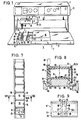
- the essential parts of the device, generally designated 2, in the form of a manipulator are a holding frame 3 for printed circuit boards 4, which is arranged at the front with respect to the operating side 5 of the device 2, a bridge-shaped which is offset with respect to the holding frame 3 towards the rear and extends parallel to the operating side 5 Guide part 6, on the bottom of which a guide arm 8 is mounted on the underside of a horizontal crossbar 9 in a cross guide 9 shown in FIG.
- Control elements determining the function of the device are arranged on the front of the spar 7.
- the movement coordinates of the guide arm 8, on which the pick-and-place tool carried by the tool head 12, which in the present exemplary embodiment is a suction needle 18, on the plane of the printed circuit board 4 at every point in the coordinate system, i.e. can be moved to any point on the circuit board 4, are designated X and Y.
- a further vertical direction of movement Z is provided for the placement tool, which in the present exemplary embodiment is formed by a vertical guide 19 (FIG. 4) between the guide arm 8 and the placement head 12.
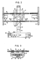
- the essential parts of the cross guide 9 shown in FIG. 2 are two guide rails 21 in the form of round rods which extend parallel to the axis X in the horizontal plane and are fastened to the side cheeks 22 of the guide part 6, a guide plate 23 which is located between the guide rails 21 and the guide arm 8 extends ( Figure 3) and three guide rollers 24, 25, of which the guide rollers designated 24 cooperate with the guide rails 21 and give the X-guide 26, while the guide rollers labeled 25 cooperate with the guide arm 8 and the Y guide result 27.
- the guide rollers 24, 25 have an X-shaped lateral surface with which they guide the guide rails 21 and the laterally rounded guide arm 8 grasp so that the guide is secured in the horizontal.
- the guide arm 8 consists of a flattened tube, ie it has flat top and bottom sides and rounded side surfaces.
- the guide rollers 24, 25 engage around the guide rails 21 and the guide arm 8 at three points, respectively, which ensures precise guidance in a simple manner.
- the cross guide 9 is assigned two brakes 28, 29, of which the brake 28 optionally blocks the movement of the guide plate 23 in the X direction and the brake 29 optionally blocks the movement of the guide arm 8 in the Y direction.
- the brakes 28, 29 are electromagnetic brakes, each with an electromagnet 31, 32 and an associated braking element, which is rod-shaped in the present exemplary embodiment, namely a metal band 33, 34 made of ferromagnetic material, which extends along the X and Y directions.
- the brakes 28, 29 can be seen in detail in FIG. 3.
- the metal band 33 of the X brake 28 is fastened to the side cheeks 22 by means of fastening angles 35, while the metal band 34 of the Y brake 29 is fastened to the underside of the guide arm 8, preferably by means of screws arranged on the free ends of the metal band 34.
- the metal strips 33, 34 each consist of two flat strips arranged one above the other, between which there is an insulation layer or an insulation strip made of soft or tough or elastic material.
- a double-sided adhesive strip is preferably made of plastic or paper and is preferably glued to the flat tapes 36. This avoids vibrations and the generation of acoustic tones when the brake is applied.
- the electromagnet 31 of the X brake 28 is arranged on the guide plate 23, while the electromagnet 32 of the Y brake 29 is arranged below the guide arm 8 on a U-bracket 38 which engages underneath the latter and passes through on the underside of the guide plate 23 Screws is attached.
- the assembly tool formed by the suction needle 18 can be displaced in the vertical Z guide, generally designated 19, by a vertical displacement of the assembly head 12.
- the suction needle 18 in the mounting head 12 in a designated 39 vertical guide preferably by only a few millimeters, which is indicated by the double arrow Z1.
- Both vertical guides 19, 39 are roller bearing guides and therefore of high precision.
- the Z-guide 19 has a vertical round guide rod 43 which can be displaced with a roller bearing cage in a vertical guide piece 44 fastened to the guide arm 8.
- a second vertical guide rod 45 is in the box-shaped housing 46 of the Placement head 12 arranged, which is also gripped with precision by a side extension 47 of the guide piece 44.
- a leaf spring 48 acting between the guide piece 44 or add-on parts and the housing 46, the assembly head 12 is loaded into its upper end position.
- the vertical guide 19 is also assigned a brake, generally designated 51, which also has an electromagnetic brake connected to a circuit, not shown, with an electromagnet 52 and a braking surface made of ferromagnetic material, which in the present exemplary embodiment is also arranged on a metal strip that runs along the electromagnet 52 is held so that the latter can be arranged immovably.
- the electromagnet 52 is fastened to a holder 54 which is fastened to the extension 47 starting from the guide piece 44.
- the metal band is a plate 53, which is fixed in the vertical position by means of a leaf spring 55 attached to it on the side wall 56 of the housing 46 in such a way that it can be deflected along the electromagnet 52 in order to lie on the end face without a gap when the electromagnet 52 is acted upon.
- the arrangement is such that a small air gap is present between the electromagnet 31, 32, 52 and the associated metal strips 33, 34 or plate 53. As a result, grinding noises are avoided if the placement head 12 is adjusted when the brakes are released.
- a switch 61 in the present exemplary embodiment is arranged on the assembly tool formed by the suction needle 18 on the upper side of the assembly head 12, which is near the uppermost position of the suction needle 18 is actuated in the direction of movement designated Z1. It is a so-called. Translation switch to achieve that the circuit is achieved with the smallest possible movement of the suction needle 18 in the Z 1 direction of movement.
- the switch 61 is a non-contact switch with a movable switching element 62 and a stationary switching element 63.
- the movable switching element 62 is mounted in the form of a single-armed lever 64 at 65, which can be pivoted vertically at 65, which is brought into its contact position by means of a spring, preferably a leaf spring 66 is applied to the stationary switching element 63.
- the suction needle 18, which is normally in its lower position due to its own weight or due to spring force, normally presses the lever 64 with an actuating member 67, as a result of which the switch 61 is opened. As soon as the suction needle 18 is raised slightly, the switch 61 is closed by means of the leaf spring 66.
- the placement head 12 in the area of the Z-guide 19 is assigned a second, indicated switch 71, FIG. 4, which functions in an area between the bottom and the top position of the placement head 12 (preferably in the middle area) between these positions the brakes 28,29,51 prevents.
- This switch is actuated by two guide pieces of the Z guide which are adjusted relative to one another, here by the housing 46 to which the switch 71 is fastened, and the guide piece 44.
- the magazine 14 comprises a magazine rod 81 in the form of a profile rail with a plurality of magazine boxes 82 which - since the present device is intended for equipping small SMD components 15 - are designed to be relatively small.
- magazine boxes 82 which can be opened and closed by means of a cover, preferably a hinged cover 83, which are only opened for the short period of time of the loading. This prevents components 15 from inadvertently getting into wrong magazine boxes 82, thereby eliminating incorrectly loaded components.
- the magazine 14 is arranged in the vicinity of the holding frame 3 for the printed circuit boards 4 in order to avoid long transport routes for the components 15 between the magazine 14 and the printed circuit board 4 as far as possible.
- the magazine 14 is located to the left of the holding frame 3. However, it could also be arranged to the right of and / or in front of or behind the holding frame 3.
- a magazine holder 84 is arranged on the frame 17, which, in a manner comparable to the holding frame 3, has two horizontal holding strips 85, one of which is preferably either in the form of a clamping strip 86 or has one .
- the magazine rod 81 is inserted between the holding strips 85 and is held in a flexible manner by means of the clamping strip 86.
- the arrangement is such that the bottom 87 of the magazine boxes 82 is approximately at the level of the circuit board 4 held.
- the hinged cover 83 located on the top of the associated magazine box 82 is on the The side of the magazine box 82 facing away from the printed circuit board 4 is pivotably mounted about an essentially horizontal joint 88, wherein it has a locking mechanism, preferably in the form of a snap lock 89, on the side facing the printed circuit board 4.
- This snap lock 89 can be opened manually, preferably with the aid of the insertion tool, here the suction needle 18.
- the latching closure 89 has a latching lug 91, which in the present exemplary embodiment is arranged on a substantially vertically extending latching arm 92, which can be adjusted by pushing it sideways away from its latched position and is returned to its latched position by spring force or, preferably, elastically, in which it is used his latching nose 91 a latching edge or surface on the hinged cover 83, here overlaps the top.
- the latching lug 91 has an inclined surface 93 on the upper side, which is inclined toward the side facing away from the printed circuit board 4.
- the snap closure 89 can thus be opened with the suction needle 18 either by a vertical movement downwards or a horizontal movement of the suction needle 18 in the direction of the printed circuit board 4 by pressing against the latching lug 91, the hinged cover 83 automatically being released after the latching lug 91 has been released Spring cover pops up.
- the hinged lid 83 has a recess 94 next to the latching lug 91, namely on its side facing away from the printed circuit board 4, which is narrower than the latching lug 91, so that the latter has the edges of the recess 94 is able to spread.
- the magazine boxes 82 are preferably made of plastic.
- the latch arm 92 integrally formed on the associated side wall of the magazine box 82, preferably in the form of a double-armed lever, so that the latching lug 91 can optionally be actuated by acting on the upper or lower lever arm 92.1 (pull or push actuation).
- the locking arm 92 is connected in the central region by connecting pieces 96 to the side wall 95, about which it can be pivoted in the sense of a joint 97 with a horizontal axis. To ensure free pivotability, 98.99 are provided on the inside of the locking lever and on the side of the recess.
- the magazine box 82 is a plastic injection molded part
- claw-shaped clamping elements 101 with clamping lugs 102 are provided, which engage behind the undercuts on the magazine rod 81.
- the undercuts are formed by inclined surfaces 103 which, owing to their inclined position, allow the magazine boxes 82 to be removed easily by simply pulling the magazine boxes upwards with little effort, the clamping elements 101 being pressed outwards.
- further inclined surfaces 104 are arranged on the top of the inclined surfaces 103, by means of which the clamping elements 101 are pressed apart when clipped on.
- the magazine boxes 82 are arranged in one row, by means of a magazine rod 81. It is also possible to arrange the magazine boxes 82 or rods in two or more rows, a corresponding number of magazine holders 84 having to be provided.
- the holding frame 3 To populate a circuit board 4, this is in the holding frame 3 to hold.
- the holding frame 3 has two further holding strips 85 extending transversely to the operating side 5, of which the left holding strip is rigid and the right holding strip 85 is displaceable and by means of a guide extending parallel to the operating side 5 or on a guide rail 113 forming this guide a locking screw 120 is optionally lockable.
- the upper edges of the holding strips 85 are stepped in mirror image, so that there are supports for the printed circuit board 4 and the latter overlapping lateral webs.
- the assembly tool on the assembly head 12 is a suction needle, by means of which a component 15 is removed from the magazine 14 and placed on the printed circuit board 4 at the predetermined location.
- a suction needle by means of which a component 15 is removed from the magazine 14 and placed on the printed circuit board 4 at the predetermined location.
- the suction needle is to be guided to a magazine box 82 containing the predetermined component 15, of which only two are shown in FIG. 1 for reasons of simplification.
- the movement of the suction needle 18 takes place by selectively displacing the mounting head 12 in the three directions of movement X, Y and Z already described.
- the predetermined magazine box 82 is opened by means of the suction needle 18, for which purpose the latter either from top to bottom against the inclined surface 93 or from the side against the locking lug 91 or the locking arm 92 is to be moved.
- the hinged cover 83 in question opens and the suction needle 18 can be lowered into the opened magazine box 82 in order to receive a component 15 by means of the suction air at the suction tip 115 of the suction needle.
- the suction needle is moved over the circuit board 4 and placed by moving the mounting head 12 down at the specific mounting location.
- the third brake 51 can also be switched on by actuating a tiltable switching element 116 of a switch 117, which in the present exemplary embodiment is also arranged on the top of the mounting head 12 and above the suction needle 18, whereby the suction needle 18 in all directions of movement X, Y, Z is locked.
- the suction needle exerts a holding function on the component 15 located between its tip and the printed circuit board 4. This is particularly advantageous in those cases in which the component is to be attached to the printed circuit board 4 by further manual handling, such as, in particular, soldering and gluing.
- the mounting head 12 Due to the locking of the suction needle 18 also in the vertical Z-direction of movement, the mounting head 12 no longer needs to be held by hand and the operator therefore has both hands free, for example to guide the soldering iron with one hand and a soldering iron with the other hand .
- the switch 117 and thus also the brake 51 which is effective in the vertical Z movement direction can be switched off, after which the mounting head can be pushed up or pushed up by the force of the leaf spring 66.
- the actuation of the switch 61 is canceled and thus the brakes 28, 29 are released so that a new placement or repair process can take place.
- the suction air circuit for receiving a component from the printed circuit board 4 (repair) or a next component 15 from the magazine 14 takes place automatically by lightly pressing the suction needle 18 against the component, as a result of which the switch 61 is actuated and the suction air is switched on.
- the suction needle 18 is generally inserted and the switch 61 is actuated.
- the switch 71 ensuring this must be adapted to the level S (FIG. 8) predetermined by the magazine box height. That is, in the present exemplary embodiment, the brakes 28, 29 are switched on and the suction air is switched off only when the switch 71 is actuated, i. possible in the lower area of the Z movement.
- both the suction needle 18 and the handle 13 are mounted rotatably about its vertical axis in the assembly head, a rotary drive being provided between the upper ends of the suction needle 18 and the shaft of the handle 13 which passes through the assembly head 12.
- a belt drive with pulleys 118 and a belt 119, preferably a toothed belt is assigned.
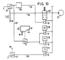
- an electromagnetically actuated shut-off valve 123 is arranged in the suction line 122 leading from a vacuum source 121 to the suction needle 18, the electromagnet 124 of which is connected to the switch 61 by an electrical line 125, in line 125 -
- a changeover switch 126 or a flip-flop is arranged. As a result, when the switch 61 is actuated one after the other, the changeover switch 126 is alternately switched over, so that the suction air is alternately switched on and off.
- An electrical line 127 branches off between the switches 61 and 126, in which the switch 71 is arranged, and in the further course of which the electromagnets 31 and 32 of the brakes 28 and 29 are arranged in parallel.
- the circuit diagram shows the suction needle 18 in the raised position (switch 61 is closed) and the insertion head 12 in the lowered position, so that the brakes 28, 29 can be closed. In the raised position of the placement head 12, it is not possible to close the brakes 28, 29 as desired.
- the closing and opening of the brakes 28, 29 is therefore dependent on the first dependence on the switch 71 and in the second dependence on the switch 61 and independently of the position of the changeover switch 126.
- the brake 51 effective in the vertical Z movement direction can be independent of the ones described above Operating states can be optionally closed and opened by manually operating switch 117.
- the electromagnet 52 of the brake 51 is in a leading from the switch 117 electrical line 129 arranged.
- the exemplary embodiment according to FIG. 11 differs from the previously described ones in that the magazine boxes of the magazine 131, designated here by 82, are not opened automatically by means of the suction needle 18, but rather automatically. This is achieved in that the magazine boxes 82, only one of which is shown, of the magazine here designated 131 for removing one or more components 15 are moved into a position of use and are automatically opened in this position generally designated 132.
- the magazine boxes 82 are placed on a transport element, e.g. a conveyor belt 133, arranged all around.
- the locking mechanism is opened directly in front of or in the use position 132.
- a stop or, in the present exemplary embodiment, by a pressure piece 134, which is either actuated separately or protrudes into the path of movement of the magazine boxes 82.
- a resilient pressure piece 134 is arranged, which in the position of use meets the latch arm 92.1 and is actuated by the press piece 134 to release the hinged lid latch, the hinged lid 83 opening. Since the pressure piece 134 is resiliently mounted, it can be easily pushed in through the associated side wall of the magazine box 82 in question. when it comes into contact with the locking arm 92.1 due to its pretensioning force and triggers the opening of the hinged cover 82.
- the hinged cover 82 is closed again by hand after the required components 18 have been removed.
- the latter can in particular in the second embodiment FIG. 11 also take place automatically, in particular during the movement of the magazine box 82 in question from the use position 132.
- the switch 71 is not necessary.
- the second exemplary embodiment according to FIG. 11 corresponds to the first exemplary embodiment according to FIGS. 1 to 10, so that a further functional description can be dispensed with.
Landscapes
- Engineering & Computer Science (AREA)
- Manufacturing & Machinery (AREA)
- Microelectronics & Electronic Packaging (AREA)
- Supply And Installment Of Electrical Components (AREA)
- Electric Connection Of Electric Components To Printed Circuits (AREA)
Applications Claiming Priority (2)
| Application Number | Priority Date | Filing Date | Title |
|---|---|---|---|
| DE3813097A DE3813097A1 (de) | 1988-04-19 | 1988-04-19 | Geraet zum bestuecken und/oder verloeten bzw. verkleben von elektronischen bauelementen auf leiterplatten |
| DE3813097 | 1988-04-19 |
Publications (3)
| Publication Number | Publication Date |
|---|---|
| EP0338454A2 true EP0338454A2 (fr) | 1989-10-25 |
| EP0338454A3 EP0338454A3 (fr) | 1991-07-10 |
| EP0338454B1 EP0338454B1 (fr) | 1994-10-19 |
Family
ID=6352372
Family Applications (1)
| Application Number | Title | Priority Date | Filing Date |
|---|---|---|---|
| EP89106734A Expired - Lifetime EP0338454B1 (fr) | 1988-04-19 | 1989-04-14 | Dispositif de montage et/ou de soudage ou de collage de composants électroniques sur circuits imprimés |
Country Status (4)
| Country | Link |
|---|---|
| US (1) | US4934578A (fr) |
| EP (1) | EP0338454B1 (fr) |
| DE (2) | DE3813097A1 (fr) |
| HK (1) | HK80097A (fr) |
Cited By (2)
| Publication number | Priority date | Publication date | Assignee | Title |
|---|---|---|---|---|
| EP0424961B1 (fr) * | 1989-10-27 | 1996-04-03 | Fritsch, Markus | Appareil à planter les composants |
| CN107742737A (zh) * | 2017-09-06 | 2018-02-27 | 深圳市赢合科技股份有限公司 | 一种自调节载具机构 |
Families Citing this family (8)
| Publication number | Priority date | Publication date | Assignee | Title |
|---|---|---|---|---|
| WO1991017860A1 (fr) * | 1990-05-22 | 1991-11-28 | Vladimir Alexeevich Maximov | Dispositif d'assemblage d'articles |
| US5634746A (en) * | 1992-09-21 | 1997-06-03 | The Boeing Co. | Normality control for a tool nose |
| US5433368A (en) * | 1992-11-10 | 1995-07-18 | Spigarelli; Donald J. | Soldering system |
| US5628660A (en) * | 1994-04-28 | 1997-05-13 | Matsushita Electric Industrial Co., Ltd. | Bonding apparatus and bonding method of devices |
| IT1291779B1 (it) | 1997-02-17 | 1999-01-21 | Magnetek Spa | Procedimento per la realizzazione di circuiti stampati e circuiti stampati cosi'ottenuti |
| JPH11340695A (ja) * | 1998-05-25 | 1999-12-10 | Sony Corp | 組立装置 |
| DE19911088A1 (de) * | 1999-03-12 | 2000-09-28 | Fraunhofer Ges Forschung | Manuell geführtes Montagesystem |
| CN117245357A (zh) * | 2022-06-10 | 2023-12-19 | 富泰华工业(深圳)有限公司 | 拆解设备 |
Family Cites Families (8)
| Publication number | Priority date | Publication date | Assignee | Title |
|---|---|---|---|---|
| US3893232A (en) * | 1973-08-16 | 1975-07-08 | Ibm | Electronic component assembly apparatus |
| US4151945A (en) * | 1977-12-08 | 1979-05-01 | Universal Instruments Corporation | Automated hybrid circuit board assembly apparatus |
| DE2846262A1 (de) * | 1978-10-24 | 1980-05-08 | Alfred Lemmer | Bestueckungstisch fuer leiterplatten |
| SU790037A1 (ru) * | 1979-02-09 | 1980-12-23 | Предприятие П/Я Р-6495 | Устройство дл присоединени кристаллов |
| SE454643B (sv) * | 1983-06-13 | 1988-05-16 | Sincotron Aps | Sett och anordning for att pa ett kretskort montera elektroniska komponenter |
| DE8508949U1 (de) * | 1985-03-26 | 1985-05-15 | Royonic Elektronik Produktionsmaschinen GmbH, 8057 Eching | Abgabegerät (II) |
| JPS63835A (ja) * | 1986-06-20 | 1988-01-05 | Pioneer Electronic Corp | 光学式情報記録担体 |
| JPS63836A (ja) * | 1986-06-20 | 1988-01-05 | Toshiba Corp | 情報記録媒体の製造方法 |
-
1988
- 1988-04-19 DE DE3813097A patent/DE3813097A1/de not_active Ceased
-
1989
- 1989-04-14 DE DE58908510T patent/DE58908510D1/de not_active Expired - Fee Related
- 1989-04-14 EP EP89106734A patent/EP0338454B1/fr not_active Expired - Lifetime
- 1989-04-18 US US07/340,122 patent/US4934578A/en not_active Expired - Fee Related
-
1997
- 1997-06-12 HK HK80097A patent/HK80097A/xx not_active IP Right Cessation
Cited By (3)
| Publication number | Priority date | Publication date | Assignee | Title |
|---|---|---|---|---|
| EP0424961B1 (fr) * | 1989-10-27 | 1996-04-03 | Fritsch, Markus | Appareil à planter les composants |
| CN107742737A (zh) * | 2017-09-06 | 2018-02-27 | 深圳市赢合科技股份有限公司 | 一种自调节载具机构 |
| CN107742737B (zh) * | 2017-09-06 | 2019-07-19 | 深圳市赢合科技股份有限公司 | 一种自调节载具机构 |
Also Published As
| Publication number | Publication date |
|---|---|
| DE58908510D1 (de) | 1994-11-24 |
| EP0338454B1 (fr) | 1994-10-19 |
| EP0338454A3 (fr) | 1991-07-10 |
| US4934578A (en) | 1990-06-19 |
| HK80097A (en) | 1997-06-20 |
| DE3813097A1 (de) | 1989-11-02 |
Similar Documents
| Publication | Publication Date | Title |
|---|---|---|
| DE69400884T2 (de) | Fassung zum Testen von integrierten Schaltkreisen | |
| DE69213475T2 (de) | Bandförmige verpackungseinrichtung mit abnehmbaren deckeln | |
| DE3905468C2 (fr) | ||
| EP0268881A1 (fr) | Dispositif pour l'essai et le classement d'éléments électronique en particulier IC's | |
| DE3402334A1 (de) | Disketten-transportvorrichtung | |
| EP0338454B1 (fr) | Dispositif de montage et/ou de soudage ou de collage de composants électroniques sur circuits imprimés | |
| DE3611789A1 (de) | Haltevorrichtung zum aufnehmen, transportieren und ablegen von kleinbauteilen | |
| DE2207914C3 (de) | Vorrichtung zum Einsetzen elektrischer Bauteile | |
| DE102019211603A1 (de) | Substratmagazin, Substratmagazinsystem und Substratbestückungsanlage | |
| DE2747164A1 (de) | Vorrichtung zur handhabung elektrischer bauteile | |
| DE8706525U1 (de) | Handhabungseinrichtung | |
| EP1636031B1 (fr) | Support de tampon deplaçable de machine a imprimer utilisee en tampographie | |
| EP0344793A2 (fr) | Dispositif de montage et/ou de soudage ou de collage de composants électroniques, notamment de composants SMD sur circuits imprimés | |
| EP0338502B1 (fr) | Dispositif de montage et/ou de soudage ou de collage de composants électroniques, en particulier de composants CMS, sur circuits imprimés | |
| DE3712087C2 (fr) | ||
| DE3935930A1 (de) | Bestueckungsgeraet | |
| DE2610120A1 (de) | Transportvorrichtung fuer flexible magnetplatten eines diktiergeraetes | |
| DE2242258C2 (de) | Zangenartige Vorrichtung zum Abziehen von Bauteilen | |
| DE3605932A1 (de) | Vorrichtung zum einsetzen von bauelementen in gedruckte schaltungsplatinen | |
| DE112021006852T5 (de) | Montagesystem und Verfahren zum Wechseln von Bandzuführern | |
| DE2557016C2 (fr) | ||
| BE1031819B1 (de) | Ausgabevorrichtung für Erzeugnisse | |
| DE10241997B4 (de) | Magazin mit Aufnahmen für Pipetten zum Bestücken von Substraten mit elektrischen Bauelementen | |
| CH686807A5 (de) | Zufuehreinheit fuer in Gurten verpackte Bauelemente zur Beschickung von Bestueckungsautomaten. | |
| EP4592029A1 (fr) | Magasin pour un module d'enfoncement |
Legal Events
| Date | Code | Title | Description |
|---|---|---|---|
| PUAI | Public reference made under article 153(3) epc to a published international application that has entered the european phase |
Free format text: ORIGINAL CODE: 0009012 |
|
| AK | Designated contracting states |
Kind code of ref document: A2 Designated state(s): CH DE FR GB LI NL |
|
| PUAL | Search report despatched |
Free format text: ORIGINAL CODE: 0009013 |
|
| AK | Designated contracting states |
Kind code of ref document: A3 Designated state(s): CH DE FR GB LI NL |
|
| 17P | Request for examination filed |
Effective date: 19910729 |
|
| 17Q | First examination report despatched |
Effective date: 19930202 |
|
| GRAA | (expected) grant |
Free format text: ORIGINAL CODE: 0009210 |
|
| AK | Designated contracting states |
Kind code of ref document: B1 Designated state(s): CH DE FR GB LI NL |
|
| REF | Corresponds to: |
Ref document number: 58908510 Country of ref document: DE Date of ref document: 19941124 |
|
| ET | Fr: translation filed | ||
| GBT | Gb: translation of ep patent filed (gb section 77(6)(a)/1977) |
Effective date: 19950124 |
|
| RAP2 | Party data changed (patent owner data changed or rights of a patent transferred) |
Owner name: FRITSCH, MARKUS |
|
| REG | Reference to a national code |
Ref country code: CH Ref legal event code: PUE Owner name: MARKUS FRITSCH |
|
| NLXE | Nl: other communications concerning ep-patents (part 3 heading xe) |
Free format text: PAT.BUL.06/95 CORR.:FRITSCH, MARKUS |
|
| PLBE | No opposition filed within time limit |
Free format text: ORIGINAL CODE: 0009261 |
|
| STAA | Information on the status of an ep patent application or granted ep patent |
Free format text: STATUS: NO OPPOSITION FILED WITHIN TIME LIMIT |
|
| 26N | No opposition filed | ||
| PGFP | Annual fee paid to national office [announced via postgrant information from national office to epo] |
Ref country code: CH Payment date: 20010420 Year of fee payment: 13 |
|
| REG | Reference to a national code |
Ref country code: GB Ref legal event code: IF02 |
|
| PGFP | Annual fee paid to national office [announced via postgrant information from national office to epo] |
Ref country code: GB Payment date: 20020403 Year of fee payment: 14 |
|
| PGFP | Annual fee paid to national office [announced via postgrant information from national office to epo] |
Ref country code: NL Payment date: 20020416 Year of fee payment: 14 Ref country code: FR Payment date: 20020416 Year of fee payment: 14 |
|
| PG25 | Lapsed in a contracting state [announced via postgrant information from national office to epo] |
Ref country code: LI Free format text: LAPSE BECAUSE OF NON-PAYMENT OF DUE FEES Effective date: 20020430 Ref country code: CH Free format text: LAPSE BECAUSE OF NON-PAYMENT OF DUE FEES Effective date: 20020430 |
|
| PGFP | Annual fee paid to national office [announced via postgrant information from national office to epo] |
Ref country code: DE Payment date: 20020628 Year of fee payment: 14 |
|
| REG | Reference to a national code |
Ref country code: CH Ref legal event code: PL |
|
| PG25 | Lapsed in a contracting state [announced via postgrant information from national office to epo] |
Ref country code: GB Free format text: LAPSE BECAUSE OF NON-PAYMENT OF DUE FEES Effective date: 20030414 |
|
| PG25 | Lapsed in a contracting state [announced via postgrant information from national office to epo] |
Ref country code: NL Free format text: LAPSE BECAUSE OF NON-PAYMENT OF DUE FEES Effective date: 20031101 Ref country code: DE Free format text: LAPSE BECAUSE OF NON-PAYMENT OF DUE FEES Effective date: 20031101 |
|
| NLV4 | Nl: lapsed or anulled due to non-payment of the annual fee |
Effective date: 20031101 |
|
| GBPC | Gb: european patent ceased through non-payment of renewal fee |
Effective date: 20030414 |
|
| PG25 | Lapsed in a contracting state [announced via postgrant information from national office to epo] |
Ref country code: FR Free format text: LAPSE BECAUSE OF NON-PAYMENT OF DUE FEES Effective date: 20031231 |
|
| REG | Reference to a national code |
Ref country code: FR Ref legal event code: ST |