EP0338717A2 - Verbinderanordnung - Google Patents
Verbinderanordnung Download PDFInfo
- Publication number
- EP0338717A2 EP0338717A2 EP89303563A EP89303563A EP0338717A2 EP 0338717 A2 EP0338717 A2 EP 0338717A2 EP 89303563 A EP89303563 A EP 89303563A EP 89303563 A EP89303563 A EP 89303563A EP 0338717 A2 EP0338717 A2 EP 0338717A2
- Authority
- EP
- European Patent Office
- Prior art keywords
- connector assembly
- spigot
- members
- conductive paths
- spigot members
- Prior art date
- Legal status (The legal status is an assumption and is not a legal conclusion. Google has not performed a legal analysis and makes no representation as to the accuracy of the status listed.)
- Withdrawn
Links
- 230000000694 effects Effects 0.000 claims abstract description 9
- 125000006850 spacer group Chemical group 0.000 claims description 4
- 238000005260 corrosion Methods 0.000 claims description 2
- 230000007797 corrosion Effects 0.000 claims description 2
- 230000006866 deterioration Effects 0.000 claims description 2
- RIBGNAJQTOXRDK-UHFFFAOYSA-N 1,3-dichloro-5-(3-chlorophenyl)benzene Chemical compound ClC1=CC=CC(C=2C=C(Cl)C=C(Cl)C=2)=C1 RIBGNAJQTOXRDK-UHFFFAOYSA-N 0.000 description 6
- 239000000463 material Substances 0.000 description 5
- 239000000853 adhesive Substances 0.000 description 3
- 230000001070 adhesive effect Effects 0.000 description 3
- 238000007373 indentation Methods 0.000 description 3
- PXHVJJICTQNCMI-UHFFFAOYSA-N Nickel Chemical compound [Ni] PXHVJJICTQNCMI-UHFFFAOYSA-N 0.000 description 2
- 229910000831 Steel Inorganic materials 0.000 description 2
- 229920001971 elastomer Polymers 0.000 description 2
- 230000003993 interaction Effects 0.000 description 2
- 239000004033 plastic Substances 0.000 description 2
- 229920003023 plastic Polymers 0.000 description 2
- 238000007493 shaping process Methods 0.000 description 2
- 239000010935 stainless steel Substances 0.000 description 2
- 229910001220 stainless steel Inorganic materials 0.000 description 2
- 239000010959 steel Substances 0.000 description 2
- 229910001229 Pot metal Inorganic materials 0.000 description 1
- 229910045601 alloy Inorganic materials 0.000 description 1
- 239000000956 alloy Substances 0.000 description 1
- 230000001627 detrimental effect Effects 0.000 description 1
- 239000000806 elastomer Substances 0.000 description 1
- 238000005516 engineering process Methods 0.000 description 1
- 239000011521 glass Substances 0.000 description 1
- 239000002184 metal Substances 0.000 description 1
- 229910052751 metal Inorganic materials 0.000 description 1
- 238000000034 method Methods 0.000 description 1
- 229910052759 nickel Inorganic materials 0.000 description 1
- 239000012815 thermoplastic material Substances 0.000 description 1
- 238000009827 uniform distribution Methods 0.000 description 1
Images




Classifications
-
- H—ELECTRICITY
- H01—ELECTRIC ELEMENTS
- H01R—ELECTRICALLY-CONDUCTIVE CONNECTIONS; STRUCTURAL ASSOCIATIONS OF A PLURALITY OF MUTUALLY-INSULATED ELECTRICAL CONNECTING ELEMENTS; COUPLING DEVICES; CURRENT COLLECTORS
- H01R12/00—Structural associations of a plurality of mutually-insulated electrical connecting elements, specially adapted for printed circuits, e.g. printed circuit boards [PCB], flat or ribbon cables, or like generally planar structures, e.g. terminal strips, terminal blocks; Coupling devices specially adapted for printed circuits, flat or ribbon cables, or like generally planar structures; Terminals specially adapted for contact with, or insertion into, printed circuits, flat or ribbon cables, or like generally planar structures
- H01R12/50—Fixed connections
- H01R12/59—Fixed connections for flexible printed circuits, flat or ribbon cables or like structures
- H01R12/62—Fixed connections for flexible printed circuits, flat or ribbon cables or like structures connecting to rigid printed circuits or like structures
-
- H—ELECTRICITY
- H05—ELECTRIC TECHNIQUES NOT OTHERWISE PROVIDED FOR
- H05K—PRINTED CIRCUITS; CASINGS OR CONSTRUCTIONAL DETAILS OF ELECTRIC APPARATUS; MANUFACTURE OF ASSEMBLAGES OF ELECTRICAL COMPONENTS
- H05K3/00—Apparatus or processes for manufacturing printed circuits
- H05K3/36—Assembling printed circuits with other printed circuits
- H05K3/361—Assembling flexible printed circuits with other printed circuits
- H05K3/365—Assembling flexible printed circuits with other printed circuits by abutting, i.e. without alloying process
Definitions
- This invention relates to a connector assembly and, in particular, a connector assembly which enables conductive paths of a first body to be electrically connected to the conductive paths of a second body.
- a connector assembly which enables conductive paths of a first body to be electrically connected to conductive paths of a second body, includes: - at least two spigot members, each of which engages with a surface of the first body, and protrudes therethrough, and has a groove formed therein; and - a connecting member which comprises a cover member into which a relisient member and a displaceable member are assembled; and where each of the cover member, resilient member and displaceable member are provided with a co-operating orifice which forms a passageway shaped to co-operate with the groove in a respective spigot member, wherein in order to effect electrical connection between the conductive paths each spigot member is inserted into a respective passageway; and the connecting member is moved relative to the spigot members so that the groove nd passageway co-operate with one another to clamp the first and second bodies together, and thereby effect electrical connection between the respective conductive paths.
- the connecting member bears against the spigot members. Thereby the resilient member is deformed and a force is transmitted via the displaceable member to the respective conductive paths, so as to enhance the electrical connection therebetween.
- the conductive paths are electrically connected to one another by surface to surface connection. That is to say, the connector assembly preferably utilises the surface mounted connector technology and principle.
- a connector assembly made in accordance with this invention is mechanically simple to operate and the electrical connection may be assembled and disassembled without any detrimental effect to the quality of the electrical connection.
- the displaceable member includes a deformable pad member.
- the inclusion of the deformable pad member in the connector assembly means that the force transmitted from the resilient member so as to enhance the electrical connection is substantial evenly distributed.
- the displaceable member further includes an interliner which is attached to the deformable pad member so that when the connector assembly is assembled the interliner is positioned between the deformable pad member and one of the two bodies.
- the interliner preferably, includes a shaped surface which interacts with the surface of the body with which it is in contact so as to further enhance the quality of the electrical connection.
- the surface of the interliner carries a number of protrusions.
- the interliner may be attached to the deformable pad member by means of adhesive.
- the interliner is provided with protrusions which extend through the deformable pad member and co-operate with holes provided in the displaceable member. In this way the interliner can be held in correct alignment to provide optimum enhancement of the quality of the electrical connection.
- the resilient member comprises a shaped Bow spring.
- the Bow spring may be manufactured from any suitable material, i.e. any material having the desired resilient qualities, for example, steel, nickel plated steel. Further, the spring may be coated/treated to prevent deterioration/corrosion thereof.
- the resilient member is mounted in the cover member of the connecting member so that it acts between the cover member and the displaceable member. In this way, the force which enhances the electrical connection, is transmitted to the displaceable member directly.
- two spigot members are mounted at opposing ends of the connector assembly, and are on either side of the conductive paths of the first and second bodies.
- each of the spigot members are of differing diameters. This ensures that the connector can only be mounted so as to interconnect the conductive paths of the two bodies in one particular orientation. Further, it enables the interliner to be correctly orientated, so that the shaped surface acts in the optimum fashion to exert the force transmitted therethrough from the resilient member. In effect this means that the force is transmitted to the two bodies preferentially in the vicinity of the conductive paths.
- each of the spigot members protrudes through both of the two bodies, to further increase the accuracy of the conductive path layout.
- each of the spigot members comprises a single unitary component, a section of which protrudes through the passageway of the first body, and which component includes a skirt section which cannot pass through the passageway and engages an under surface with respect to the connecting member of the first body.
- the connector assembly is particularly suited for use in circumstances where only one connecting member is to be mounted on the spigot members. Therefore, in this case, the conductive paths to be connected are provided with respect to one side of the first body for this electrical connection only.
- each of the spigot members comprises a two piece member, the individual pieces of which are mechanically interengageable.
- each of the two pieces of spigot members are provided with a groove to enable a connecting member to be mounted thereon.
- the connector assembly is particularly suited to enable electrical connection of conductive paths provide on both sides of the first body, by enabling connecting members to be mounted with respect to both sides of the first body by a single set of spigot members.
- each of the pieces of the spigot members preferably has a surface which engages with a surface of the first body.
- one of the pieces of the spigot member acts simply to provide a skirt member which engages with an under surface of the first body.
- the two pieces of the spigot members are mechanically interengaged by a screw threaded arrangement provided with respect thereto.
- the two spigot members may be formed as a single unit.
- the spigot members are preferably independent of one another.
- the connector assembly preferably, also includes spacers. These spacers would normally be placed around the spigot members so that the spacer, and thereby the spigot members act against the first body.
- the invention also includes a method of electrically connecting the conductive paths of a first body with the conductive paths of a second body using a connector assembly made in accordance with the present invention.
- a connector assembly made in accordance with the present invention comprises: - two spigot members 1, and - a connecting member 2.
- the connecting member 2 comprises: - a cover member 3; - a resilient member 4; and - a displaceable member 5, which includes a body member 6, a pad member 7 and an interliner 8.
- each of the spigot members 1 is manufactured from a die-cast zinc alloy.
- the spigot member may be a turned metal component.
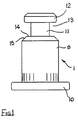
- Each spigot member is shaped so that it includes: - a cylindrical body section 9; - a base section 10 at one end of the body section 9 which extends beyond the body section 9; - a necked section 11; and - a head section 12 at the end of the body section 9 remote from the base section.
- the necked section 11, the head section 12 and the end of the body section 9 remote from the base section 10 define a groove 13. Further, the surface 14 of the body section 10 which defines a side of the groove has a tapered portion 15.
- the two spigots are of differing diameters. This ensures the connector assembly way only be used in a particular orientation.
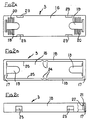
- the cover member 3 of the connecting member 2 is manufactured from a glass filled thermoplastic material and comprises: - an upper section 16; - two end walls 17; and - two side walls 18.
- the upper section 16 has two orifices 19 formed therein, and positioned one at either end of the cover member 3. In the vicinity of each of the orifices 19 ribbed sections 20 are provided to enhance the grip on the cover member when a sliding force is applied thereto.
- Each of the end walls 17 has an internally projecting abutment 21 which defines a shelf 22 at the end of the end wall remote from the upper section 16.
- Each of the side walls 18 is provided with - two openings 23 therethrough; and - has two indentations 24 on the internal surfaces 25 thereof.
- the resilient member 4 of the connecting member 2 comprises a stainless steel Bow spring which is formed with - a bowed section 26; - two arms 27; and - two keyhole orifices 28, one at each end of the bowed section 26.
- the body member 6 of the displaceable member 5 is manufactured from plastics material and comprises: - two side sections 28 a ; and - a web section 29 which extends between the two side sections 28 a .
- the web section 29 has two orifices 30, one at each end thereof.
- the outer facing surfaces of the side sections 28 are each provided with: - an abutment 31, which is positioned so that when the displaceable member 5 is mounted in the cover member 3 the abutment co-operates with one of the indentations 24; and - two projections 32, which when the displaceable member 5 is mounted in the cover member 3 co-operate with the openings 23 thereof.
- the pad member 7 of the connecting member 2 is made from a rubber/elastomer material, which deforms as a force is applied thereto.
- the deforming of the pad member 7 means that as a force is applied, the force is transmitted in a substantial uniform distribution over the length of the connector assembly as a whole.
- the interliner 8 is manufactured from a plastics material and comprises two longitudinally extending rows of offset teeth, and two orifices at the longitudinally opposed ends thereof.
- the lower surface 33 of the interliner 8 is provided with downwardly extending protrusions 34. These protrusions are set in a pattern which correspond to the desired conductive path interconnection between the two bodies.
- the pad member 7 is secured by adhesive to an under surface of the web section 29 and located between the two side sections 28 a ; and - the interliner 8 is secured to the other side of the pad member 7 by adhesive.
- the connecting member 2 may now be assembled. This is achieved by: - inserting the resilient member 4 into the cover member 3, so that the arms 27 of the member 4 engage the respective shelves 22 of the cover member; and - inserting the displaceable member 5, with the interliner 8 facing outwards into the cover member 3 so that the abutments 31 engage with respective indentations 24 and the projections 32 co-operate with the openings 23.
- the displaceable member 5 is held in the cover member 3 by the co-operation of the projections 32 and the openings 23.
- the bowed section 26 of the resilient member 4 engages with the web 29 of the displaceable member 5.
- the orifices in the interliner 8, the body member 6 of the displaceable member 5 and the cover member and the keyhole orifices in the bowed section 26 of the resilient member 4 co-operate to form two passageways through the connecting member 2.
- Each of the keyhole orifices, in at least the bowed section 26 of the resilient member 4, is shaped with a necked section. The necked sections in both of the keyhole orifices extending longitudinally in the same direction.
- each spigot member 1 engages with the necked section of the keyhole orifice 28 in the bowed section 26 of the resilient member 4.
- the interaction of the shaping on the surfaces defining the groove 13 and the necked section of the orifice help to locate the connecting member 2 correctly with respect to the spigot members 1.
- the resilient member 4 When assembled, as in the position shown in Figure 6, the resilient member 4 acts against the PCB 36 and flexible cable 38 via the displaceable member 5, and in particular the protrusions 34 on the interliner 8 so as to enhance the electrical connection between the respective conductive paths 35 and 37.
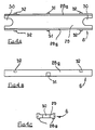
- Each of the spigot members 1 a comprises two pieces 40 and 41 made from stainless steel.
- Each of the pieces 40, 41 of the spigot member 1 a is shaped so that it includes: - a cylindrical body section 42, - a necked section 43, and - a head section 44, having a slot 45 formed therein.
- a groove 46 is defined in each piece 40, 41 of the spigot member 1 a by the cylindrical body section 42, the necked section 43 and the head section 44.
- a recessed shelf 46 is provided in each piece 40, 41 of the spigot member 1 a at the end thereof remote from the head section.
- the recessed shelf 46 and the cylindrical body section 42 of each piece defines a surface 49.
- One of the pieces 40 of the spigot member 1 a is provided with an abutment 47 extending from the recessed shelf 46 thereof, and having a screw thread formed thereon.
- the other piece 41 of the spigot member 1 a is provided with a recessed section 48 extending inwardly from the recessed shelf 46 thereof.
- the recessed section 48 is provided with a screw thread which acts with the screw thread of the abutment 47 to mechanically interconnect the two pieces of the spigot member 1 a .
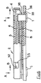
- FIG. 8 of the drawings a second form of connector assembly, in an assembled state, is shown.
- This form of connector assembly uses two of the spigot members 1 a described with reference to Figures 7a to 7c of the drawings above, and includes two connecting members 2 mounted one at each end of the spigot members and on either side of a first body 50.
- Each of the connecting members 2 is substantially identical to that described with reference to Figures 2 to 6 of the drawings, and like numerals have been used to define like components. The differences therebetween are minor and comprise: - the resilient member 4 is formed without the two arms 27; and - the interliner 8 is provided with two protrusions 51 which extend through the deformable pad member 7 and into respective holes 52 provided in the displaceable member 5.
- the protrusions 51 and the holes 52 co-operate with one another to correctly align the interliner and provide optimum enhancement of the quality of the electrical connection.
- each spigot member 1 engages with the necked section of the keyhole orifice 28 in the bowed section 26 of the resilient member 4.
- the interaction of the shaping on the surfaces defining the groove 13 and the necked section of the orifice help to locate the respective connecting member 2 correctly with respect to the spigot members 1.
- the resilient member 4 When assembled, as in the position shown in Figure 8, the resilient member 4 acts against the PCB 36 and the flexible cables 38 via the displaceable member 5, and in particular the protrusions 34 on the interliner 8 so as to enhance the electrical connection between the respective conductive paths 35 and 37.
Landscapes
- Connector Housings Or Holding Contact Members (AREA)
- Coupling Device And Connection With Printed Circuit (AREA)
- Manufacturing Of Electrical Connectors (AREA)
Applications Claiming Priority (4)
| Application Number | Priority Date | Filing Date | Title |
|---|---|---|---|
| GB888809402A GB8809402D0 (en) | 1988-04-21 | 1988-04-21 | Connector assembly |
| GB8809402 | 1988-04-21 | ||
| GB888821901A GB8821901D0 (en) | 1988-09-17 | 1988-09-17 | Connector assembly |
| GB8821901 | 1988-09-17 |
Publications (2)
| Publication Number | Publication Date |
|---|---|
| EP0338717A2 true EP0338717A2 (de) | 1989-10-25 |
| EP0338717A3 EP0338717A3 (de) | 1990-10-17 |
Family
ID=26293798
Family Applications (1)
| Application Number | Title | Priority Date | Filing Date |
|---|---|---|---|
| EP19890303563 Withdrawn EP0338717A3 (de) | 1988-04-21 | 1989-04-11 | Verbinderanordnung |
Country Status (4)
| Country | Link |
|---|---|
| US (1) | US4948374A (de) |
| EP (1) | EP0338717A3 (de) |
| JP (1) | JPH01313868A (de) |
| GB (1) | GB2220308A (de) |
Cited By (4)
| Publication number | Priority date | Publication date | Assignee | Title |
|---|---|---|---|---|
| WO1997019490A1 (de) * | 1995-11-17 | 1997-05-29 | Robert Bosch Gmbh | Elektrischer anschluss für folienleiter |
| NL1013575C2 (nl) * | 1999-11-15 | 2001-05-16 | Fci S Hertogenbosch B V | Connector en werkwijze ter vervaardiging daarvan. |
| WO2009043508A1 (de) * | 2007-09-26 | 2009-04-09 | Amphenol-Tuchel Electronics Gmbh | Hochpoliger matrixsteckverbinder |
| EP2919331A1 (de) * | 2014-03-13 | 2015-09-16 | Robert Bosch Gmbh | Kontaktsystem mit einem verriegelbar ausgebildeten Stecker |
Families Citing this family (28)
| Publication number | Priority date | Publication date | Assignee | Title |
|---|---|---|---|---|
| US5064377A (en) * | 1990-12-28 | 1991-11-12 | Seagate Technology, Inc. | Compression contact electrical connector assembly for a disc drive |
| US5259781A (en) * | 1992-11-18 | 1993-11-09 | International Business Machines Corporation | Electrical connector alignment and actuation assembly |
| JP2867209B2 (ja) * | 1993-08-27 | 1999-03-08 | 日東電工株式会社 | フレキシブル回路基板と接触対象物との接続方法およびその構造 |
| US5558523A (en) | 1994-07-15 | 1996-09-24 | International Business Machines Corporation | Pad on pad type contact interconnection technology for electronic apparatus |
| US5533908A (en) * | 1994-08-31 | 1996-07-09 | The Whitaker Corporation | Latch and mounting member for a surface mounted electrical connector |
| JP2731744B2 (ja) * | 1995-03-15 | 1998-03-25 | 日本電気株式会社 | ケーブルコネクタ |
| US5752851A (en) * | 1996-02-05 | 1998-05-19 | Ford Motor Company | Circuit clip connector |
| JP3318185B2 (ja) * | 1996-03-14 | 2002-08-26 | 矢崎総業株式会社 | 電装モジュールの組付け構造 |
| EP0979542B1 (de) * | 1996-06-28 | 2003-03-26 | Synapse Technologies, INC. | Mechanismus mit knopf und schwalbenschwanz zum aktivieren eines verbinders |
| US5730619A (en) * | 1996-07-01 | 1998-03-24 | General Motors Corporation | Externally locked connector |
| US5917709A (en) * | 1997-06-16 | 1999-06-29 | Eastman Kodak Company | Multiple circuit board assembly having an interconnect mechanism that includes a flex connector |
| US6247951B1 (en) | 1998-05-29 | 2001-06-19 | Delphi Technologies, Inc. | Flexible circuit connector |
| US6109930A (en) * | 1998-09-08 | 2000-08-29 | International Business Machines Corporation | Enhanced hardware arrangement for mounting a plurality of circuit boards together |
| DE19950757A1 (de) * | 1999-10-21 | 2001-04-26 | Bosch Gmbh Robert | Vorrichtung zur elektrischen und mechanischen Verbindung von zwei Leiterplatten |
| US6491543B1 (en) * | 2000-06-22 | 2002-12-10 | Cray Inc. | Electrical circuit connector with tapered surface |
| US6402526B1 (en) | 2000-11-03 | 2002-06-11 | Delphi Technologies, Inc. | Microelectronic contact assembly |
| US6425768B1 (en) * | 2000-11-17 | 2002-07-30 | Intercon Systems, Inc. | Clamp connector assembly |
| US6500010B2 (en) * | 2001-03-02 | 2002-12-31 | Cray Inc. | Electrical circuit connector with resilient pressure pads |
| US6612851B1 (en) * | 2002-04-09 | 2003-09-02 | Tyco Electronics Corporation | Electrical connector assembly for printed circuit boards |
| US7438582B2 (en) * | 2006-12-22 | 2008-10-21 | Amphenol Corporation | Flexible circuit connector assembly |
| SG11201408281TA (en) * | 2012-05-22 | 2015-01-29 | Nhk Spring Co Ltd | Socket attachment structure and spring member |
| US9225115B2 (en) | 2012-10-22 | 2015-12-29 | Apple Inc. | Retention key lock for board-to-board connectors |
| US9209540B2 (en) * | 2013-02-08 | 2015-12-08 | Apple Inc. | Board-to-board connectors |
| US9620844B2 (en) * | 2013-03-13 | 2017-04-11 | Samsung Electronics Co., Ltd | Connector joint support module, electronic device including the same, and methods of assembling and disassembling electronic device |
| CN204030038U (zh) * | 2013-03-25 | 2014-12-17 | 富加宜(亚洲)私人有限公司 | 电缆连接器组件和包括电缆连接器组件的电连接器系统 |
| US9755337B2 (en) | 2014-09-02 | 2017-09-05 | Apple Inc. | Waterproof board-to-board connectors |
| CN206864652U (zh) * | 2017-04-24 | 2018-01-09 | 番禺得意精密电子工业有限公司 | 电连接装置 |
| JP2024094641A (ja) * | 2022-12-28 | 2024-07-10 | 日本航空電子工業株式会社 | コネクタおよびコネクタ組立体 |
Family Cites Families (4)
| Publication number | Priority date | Publication date | Assignee | Title |
|---|---|---|---|---|
| FR2244327B1 (de) * | 1973-09-14 | 1977-05-27 | Amp Inc | |
| US4166665A (en) * | 1976-12-27 | 1979-09-04 | Cutchaw John M | Liquid cooled connector for large scale integrated circuit packages |
| US4390220A (en) * | 1981-04-02 | 1983-06-28 | Burroughs Corporation | Electrical connector assembly for an integrated circuit package |
| US4602317A (en) * | 1984-12-13 | 1986-07-22 | Gte Communication Systems Corporation | Printed wiring board connector |
-
1989
- 1989-04-11 EP EP19890303563 patent/EP0338717A3/de not_active Withdrawn
- 1989-04-18 US US07/339,988 patent/US4948374A/en not_active Expired - Fee Related
- 1989-04-19 JP JP1097691A patent/JPH01313868A/ja active Pending
- 1989-04-20 GB GB8909014A patent/GB2220308A/en not_active Withdrawn
Cited By (7)
| Publication number | Priority date | Publication date | Assignee | Title |
|---|---|---|---|---|
| WO1997019490A1 (de) * | 1995-11-17 | 1997-05-29 | Robert Bosch Gmbh | Elektrischer anschluss für folienleiter |
| NL1013575C2 (nl) * | 1999-11-15 | 2001-05-16 | Fci S Hertogenbosch B V | Connector en werkwijze ter vervaardiging daarvan. |
| WO2001037379A1 (en) * | 1999-11-15 | 2001-05-25 | F.C.I-Framatome Connectors International | Connector and method for manufacturing the same |
| US6379160B1 (en) | 1999-11-15 | 2002-04-30 | Framatome Connectors International | Metal plate mounted to connector and method for manufacturing the same |
| WO2009043508A1 (de) * | 2007-09-26 | 2009-04-09 | Amphenol-Tuchel Electronics Gmbh | Hochpoliger matrixsteckverbinder |
| US8075320B2 (en) | 2007-09-26 | 2011-12-13 | Amphenol-Tuchel Electronics Gmbh | Multipole matrix connector |
| EP2919331A1 (de) * | 2014-03-13 | 2015-09-16 | Robert Bosch Gmbh | Kontaktsystem mit einem verriegelbar ausgebildeten Stecker |
Also Published As
| Publication number | Publication date |
|---|---|
| GB2220308A (en) | 1990-01-04 |
| JPH01313868A (ja) | 1989-12-19 |
| US4948374A (en) | 1990-08-14 |
| EP0338717A3 (de) | 1990-10-17 |
| GB8909014D0 (en) | 1989-06-07 |
Similar Documents
| Publication | Publication Date | Title |
|---|---|---|
| US4948374A (en) | Assembly for electrically connecting conductive paths of a first body to conductive paths of a second body | |
| US11996654B2 (en) | Controlled-impedance compliant cable termination | |
| US10096918B1 (en) | Connector | |
| US4129351A (en) | Connector assembly for printed circuit board | |
| US4422128A (en) | Push-on terminal clip and assembly | |
| US4955814A (en) | Electrical connector device | |
| EP0233914B1 (de) | An einer oberfläche montierter verbinder | |
| US5427546A (en) | Flexible jumper with snap-in stud | |
| US5462441A (en) | Low profile electrical connector | |
| US5405267A (en) | Board-mounting rack for plurality of electrical connectors | |
| JPH05826B2 (de) | ||
| US5395249A (en) | Solder-free backplane connector | |
| US4548450A (en) | Terminal pin securing arrangement | |
| US4797110A (en) | Printed circuit board with integral electrical connector and method for making it using wave soldering | |
| US5090912A (en) | Arrangement for the mechanical and electrical connection of a supplementary printed circuit board to a base printed circuit board | |
| GB2147145A (en) | Diamond heatsink assemblies | |
| US4385341A (en) | Strain relief member for flat flexible cables | |
| US5002507A (en) | Circuit board contact element and compliant section thereof | |
| SE453032B (sv) | Kombination av kontaktdon | |
| JP3080187U (ja) | 保持装置を具えたコネクタ | |
| US4219251A (en) | Power connector | |
| US5568174A (en) | Connector and printer head using the same | |
| JP2513698B2 (ja) | 同軸ケ−ブルの分岐接続器 | |
| KR100280759B1 (ko) | 전기 핀 필드 | |
| JPH0317976A (ja) | フラットケーブル用コネクタ |
Legal Events
| Date | Code | Title | Description |
|---|---|---|---|
| PUAI | Public reference made under article 153(3) epc to a published international application that has entered the european phase |
Free format text: ORIGINAL CODE: 0009012 |
|
| AK | Designated contracting states |
Kind code of ref document: A2 Designated state(s): CH DE ES FR GB IT LI NL SE |
|
| PUAL | Search report despatched |
Free format text: ORIGINAL CODE: 0009013 |
|
| AK | Designated contracting states |
Kind code of ref document: A3 Designated state(s): CH DE ES FR GB IT LI NL SE |
|
| RAP1 | Party data changed (applicant data changed or rights of an application transferred) |
Owner name: MCMURDO LIMITED |
|
| 17P | Request for examination filed |
Effective date: 19910402 |
|
| STAA | Information on the status of an ep patent application or granted ep patent |
Free format text: STATUS: THE APPLICATION IS DEEMED TO BE WITHDRAWN |
|
| 18D | Application deemed to be withdrawn |
Effective date: 19921105 |