EP0339030B1 - Dispositif d'entrainement - Google Patents
Dispositif d'entrainement Download PDFInfo
- Publication number
- EP0339030B1 EP0339030B1 EP88900145A EP88900145A EP0339030B1 EP 0339030 B1 EP0339030 B1 EP 0339030B1 EP 88900145 A EP88900145 A EP 88900145A EP 88900145 A EP88900145 A EP 88900145A EP 0339030 B1 EP0339030 B1 EP 0339030B1
- Authority
- EP
- European Patent Office
- Prior art keywords
- arrangement
- drive part
- arrangement according
- rotational
- transmission ratio
- Prior art date
- Legal status (The legal status is an assumption and is not a legal conclusion. Google has not performed a legal analysis and makes no representation as to the accuracy of the status listed.)
- Expired - Lifetime
Links
- 230000005540 biological transmission Effects 0.000 claims abstract description 34
- 238000006073 displacement reaction Methods 0.000 claims description 2
- 238000010276 construction Methods 0.000 description 3
- 230000004048 modification Effects 0.000 description 2
- 238000012986 modification Methods 0.000 description 2
- 230000000295 complement effect Effects 0.000 description 1
- 230000000694 effects Effects 0.000 description 1
- 230000002708 enhancing effect Effects 0.000 description 1
- 230000002093 peripheral effect Effects 0.000 description 1
- 230000003319 supportive effect Effects 0.000 description 1
Images
Classifications
-
- B—PERFORMING OPERATIONS; TRANSPORTING
- B66—HOISTING; LIFTING; HAULING
- B66D—CAPSTANS; WINCHES; TACKLES, e.g. PULLEY BLOCKS; HOISTS
- B66D1/00—Rope, cable, or chain winding mechanisms; Capstans
- B66D1/60—Rope, cable, or chain winding mechanisms; Capstans adapted for special purposes
- B66D1/74—Capstans
- B66D1/7463—Accessories
- B66D1/7468—Handles
-
- B—PERFORMING OPERATIONS; TRANSPORTING
- B66—HOISTING; LIFTING; HAULING
- B66D—CAPSTANS; WINCHES; TACKLES, e.g. PULLEY BLOCKS; HOISTS
- B66D1/00—Rope, cable, or chain winding mechanisms; Capstans
- B66D1/60—Rope, cable, or chain winding mechanisms; Capstans adapted for special purposes
- B66D1/74—Capstans
- B66D1/7494—Self-tailing capstans
-
- Y—GENERAL TAGGING OF NEW TECHNOLOGICAL DEVELOPMENTS; GENERAL TAGGING OF CROSS-SECTIONAL TECHNOLOGIES SPANNING OVER SEVERAL SECTIONS OF THE IPC; TECHNICAL SUBJECTS COVERED BY FORMER USPC CROSS-REFERENCE ART COLLECTIONS [XRACs] AND DIGESTS
- Y10—TECHNICAL SUBJECTS COVERED BY FORMER USPC
- Y10T—TECHNICAL SUBJECTS COVERED BY FORMER US CLASSIFICATION
- Y10T74/00—Machine element or mechanism
- Y10T74/19—Gearing
- Y10T74/19642—Directly cooperating gears
- Y10T74/19679—Spur
-
- Y—GENERAL TAGGING OF NEW TECHNOLOGICAL DEVELOPMENTS; GENERAL TAGGING OF CROSS-SECTIONAL TECHNOLOGIES SPANNING OVER SEVERAL SECTIONS OF THE IPC; TECHNICAL SUBJECTS COVERED BY FORMER USPC CROSS-REFERENCE ART COLLECTIONS [XRACs] AND DIGESTS
- Y10—TECHNICAL SUBJECTS COVERED BY FORMER USPC
- Y10T—TECHNICAL SUBJECTS COVERED BY FORMER US CLASSIFICATION
- Y10T74/00—Machine element or mechanism
- Y10T74/20—Control lever and linkage systems
- Y10T74/20576—Elements
- Y10T74/20732—Handles
- Y10T74/20744—Hand crank
-
- Y—GENERAL TAGGING OF NEW TECHNOLOGICAL DEVELOPMENTS; GENERAL TAGGING OF CROSS-SECTIONAL TECHNOLOGIES SPANNING OVER SEVERAL SECTIONS OF THE IPC; TECHNICAL SUBJECTS COVERED BY FORMER USPC CROSS-REFERENCE ART COLLECTIONS [XRACs] AND DIGESTS
- Y10—TECHNICAL SUBJECTS COVERED BY FORMER USPC
- Y10T—TECHNICAL SUBJECTS COVERED BY FORMER US CLASSIFICATION
- Y10T74/00—Machine element or mechanism
- Y10T74/21—Elements
- Y10T74/2186—Gear casings
Definitions
- the present invention relates to a manual drive arrangement for manually driving a winch or like notably device, according to the preambule of claim 1.
- Winches of this kind are, or course, also found for use with recreational sailing vessels. These winches, however, are much more expensive than the simple winches normally used, which are in themselves relatively expensive. This renders the choice of exchanging a simple winch for winches which incorporate more than one transmission ratio economically unattractive.
- the present invention provides a winch arrangement which solves the aforedescribed problems.
- the inventive arrangement enhances the use possibilities of both simple winches and winches which incorporate more than one transmission ratio.
- the invention is defined in claim 1.
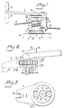
- the embodiment illustrated in Figure 1 comprises a rotatable device 1 in the form of a so-called sheet winch, comprising a rotatable shaft 2 in the form of a sleeve-like part which is actuable to rotate the device 1 and which is intended to rotate an externally located drum 3 at a given transmission ratio, and wherein auxiliary devices are provided for driving the device 1 manually, these devices comprising a preferably peg-like drive part 4 which is intended to co-act drivingly with the shaft 2, such as to rotate said shaft without mutual rotation therebetween, and also a crank arm 5 or like device which is intended to co-act with the drive part 4 in a manner to effect said rotational movement.
- the winch of the illustrated embodiment is of a known kind and is constructed solely for one operating speed and has a transmission ratio of 1:1, i.e. the-drum 3 rotates at the same speed as the shaft 2, i.e. the sleeve-like part 2.
- the sleeve-part 2 is fluted on its outer peripheral surface and is connected to a base-part 6 for rotation relative thereto, the base-part 6 being secured, e.g., to a gunwhale 8 by means of screws 7.
- the sleeve-part 2 is arranged to co-act with latching devices 9 located on the drum 3, such that the drum 3 is driven by the sleeve-like part 2 in one given direction with the latching devices engaged in a drum latching position, and is freely rotatable in the opposite direction, with the latching devices out of latching engagement with the drum.
- the reference 10 identifies a sheet or like rope which is to be hauled or pulled by means of the winch
- the reference 11 identifies latching devices which are located on the drum 3 and which co-act with an externally fluted part 6′ on the base-part 6, such as to prevent rotation of the drum in response to the tension engendered in the sheet or rope, i.e. drum rotation in a direction opposite to the direction of rotation effected by the drive part 4.
- the illustrated inventive arrangement includes devices 12 for transmitting rotary movement of the crank arm 5 to the drive part 4, i.e. the peg-like part 4, at a given transmission ratio.
- the intention herewith is to complement the transmission ratio of the winch 1 or corresponding device, and hence the transmission ratio provided by the devices 12 will preferably differ from the winch transmission ratio 1:1.
- the crank arm 5 and the drive part 4 and a gear arrangement co-acting therewith for producing said transmission ratio is suitably supported by a carrier assembly 13, including a housing 13′.
- the carrier assembly comprises holding-up parts which are essentially non-rotatable and which are stationary such as to provide counterforce surfaces during the transmission of rotational movement to the drive part 4.
- the housing 13′ or the like is suitably included by the holding-up parts.
- the holding-up parts are intended to co-act with a sheet 10 which is arranged on and extends from the drum 3, therewith to be held firm against rotation.
- a carrier arm 14 which extends essentially radially in relation to the rotational axis of the drive part 4 and which carries a support member 15 in supportive engagement with the sheet 10.
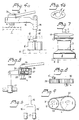
- the support member e.g. of Figures 4 and 6, may for instance have the form of a bifurcate member 15 having two legs 15′ which are intended to straddle the sheet 10.
- the support member 15 may also include an axially extending part 16 which is preferably rotatable and which extends essentially parallel with the longitudinal axis of the drive part 4, said axially extending part 16 also being arranged for limited axial movement.
- Each of the legs 15′ may be provided with a respective rotatable contact roller 17, which presents a concave outer surface for guiding the sheet 10 as shown in Figure 6.
- the legs 15′ of the bifurcate member may be given a highly polished surface finish and may conveniently be provided with a respective end stop 18.
- the holding-up parts may be arranged for connection to the gunwhale or like surface 8 to which the winch is secured, either directly or indirectly.
- the arrangement will preferably include for this purpose a connecting device which extends through a central, axial part of the winch.
- a connecting device which extends through a central, axial part of the winch.
- FIG. 7 One example of this type of winch construction is found in the self-tailing winch illustrated in Figure 7, in which an arm 19 is stationarily mounted in relation to the drum 3 and is connected to the base part 6 of the winch.
- holding-up parts can be combined with and/or caused to coact with the arm 19. It will be appreciated that the holding-up parts may be stationarily mounted in the same manner, or essentially the same manner as the arm 19, without the provision of an arm therefor .
- FIG. 4 Another example is indicated in Figure 4.
- a fitting 8′ is fixedly mounted on the gunwhale or like support surface 8 and incorporates a hole or bore 8 ⁇ into which a shank part 15′ of the member 15 is inserted and herewith locked against displacement transversely to the direction of the longitudinal axis of the shank part in response to said rotational movement.
- a support member 15 which comprises solely one shank part 15′ will suffice, i.e. a support member 15 having the configuration illustrated in Figure 4a.
- the transmission devices 12, Figure 1, by means of which the aforesaid transmission ratio is obtained may have several mutually different forms.
- the transmission ratio is obtained through a planet gear, of which the illustrated arrangement constitutes one example.
- the illustrated planet gear system includes a centrally located sun gear which is connected for rotation to the arm 5, planet wheels 21 which co-act with the sun gear 20, a circumferentially extending gear ring 22, and planet arms 23 which are connected drivingly to the drive part 4, for rotating said drive part in the illustrated manner.
- the gear system may have a construction different to that illustrated, e.g. it may comprise three planet wheels 21 and three arms 23.
- One advantage afforded by a planet gear in the present context is that is has a low vertical height.
- the desired transmission ratio is achieved through the medium of a gear transmission which includes two pairs of mutually co-acting gear wheels, of which a respective gear wheel 24, 25 of each gear wheel pair is intended for input rotational movement, produced by the crank arm 5 and for output rotational movement intended for the drive part 4, and the other gear wheels 26, 27 of each gear wheel pair are mutually connected together, e.g. by mounting said gear wheels on a common shaft 28.
- Figure 8 illustrates an embodiment in which two gear wheels 29, 30 are arranged to co-act with one another, wherewith the input rotational shaft 5′ is connected to one gear wheel and the drive part 4 is connected to the other.
- This will provide a structure of low vertical height.
- Figure 9 illustrates an embodiment in which two gear wheels 31, 32 are connected together by means of a chain 33.
- This arrangement provides a structure of low vertical height, where the shaft 5′ and the drive pump 4 rotate in mutually the same direction. A given distance is obtained between the rotational axes of the shaft 5′ and the drive part 4.
- a variant which incorporates the use of a V-belt can also be employed in this case.
- the inventive arrangement affords a particularly valuable facility for enhancing flexibility with regard to the transmission ratios of both winches that are under construction and existing winches.
- the arrangement offers an economically attractive alternative to the choice of a more expensive winch or of changing one winch for another.
- the drive part 4 consists of a sleeve-like part which is arranged to co-act drivingly with a peg-like part on the winch.
- the arrangement also conveniently includes locking devices identified generally by reference 34, intended for preventing the arrangement from being withdrawn from the sleeve-like part 2, subsequent to inserting the drive part 4 thereinto.
- These locking devices may be of any known kind, and may include a square plate 35, indicated in Figure 2, capable of being rotated by means of a shaft 37, through the medium of a knob 36, such as to bring at least one corner 38 of the plate 35 into locking engagement with an abutment surface (not shown) in the sleeve-like part 2, wherewith the plate is displaced or stepped circumferentially around the drive part 4, relative to corner parts 4′ thereof, Figure 2.
- the arrangement may also include a cotter 39 or like locking device schematically shown in Figure 4a, the cotter being intended to prevent rotation of the crank arm 5 and the drive part 4.
- a cotter 39 or like locking device schematically shown in Figure 4a, the cotter being intended to prevent rotation of the crank arm 5 and the drive part 4.
Landscapes
- Engineering & Computer Science (AREA)
- Mechanical Engineering (AREA)
- Transmission Devices (AREA)
- Gear Transmission (AREA)
- Friction Gearing (AREA)
Abstract
Claims (11)
- Dispositif d'entraînement manuel d'un treuil ou d'un agencement rotatif similaire qui comprend un arbre rotatif d'impulsion pouvant être actionné pour entraîner le dispositif rotatif et agencé pour faire tourner un tambour externe, ou un dispositif correspondant, dans un rapport de transmission donné, l'assemblage comprenant un élément d'entraînement de préférence du type cheville pour opérer un actionnement conjoint avec ledit arbre sans rotation solidaire réciproque, et comprenant en plus un bras de manivelle ou un organe similaire ayant pour fonction d'agir conjointement avec ledit élément d'entraînement de manière à produire un mouvement rotatif, l'assemblage constituant une unité mobile en direction de/ou à partir dudit dispositif rotatif, caractérisé en ce que l'assemblage comprend des dispositifs de transmission (12) ayant pour fonction de transmettre le mouvement rotatif du bras de manivelle (5) à l'élément d'entraînement (4) dans un rapport de transmission donné et différent du rapport de transmission 1/1.
- Assemblage selon la revendication 1, caractérisé en ce que le bras de manivelle (5), l'élément d'entraînement (4) et un dispositif de transmission (12), agissant conjointement, sont portés par une unité porteuse (13) du genre boîtier (13′), et en ce que des éléments (14, 15) de l'unité porteuse sont essentiellement non-rotatifs mais fixement assemblés et constituent des éléments de fixation au cours de la transmission du mouvement rotatif à l'élément d'entraînement (4).
- Assemblage selon les revendications 1 ou 2, caractérisé en ce que lesdits éléments de fixation sont fixement connectés à la surface d'appui (8) à laquelle le dispositif rotatif (1) est fixé, du type plat-bord ou similaire, l'assemblage comprenant de préférence à cette fin un dispositif de connexion qui se prolonge au travers de l'arbre central du dispositif rotatif.
- Assemblage selon la revendication 3, caractérisé en ce que les éléments de fixation ont pour fonction d'agir conjointement avec un bras de sécurité (19) d'un treuil appelé de ce fait auto-bloquant.
- Assemblage selon les revendications 1 ou 2, caractérisé en ce que les éléments de fixation (14, 15) ont pour fonction d'agir conjointement avec le câble de sécurité (10), ou similaire, enroulé et se prolongeant à partir du tambour (3), étant ainsi fermement maintenu pour résister à une quelconque rotation.
- Assemblage selon la revendication 5, caractérisé en ce que le dispositif comprend en outre un bras d'entraînement (14) se déployant vers l'extérieur, lequel se prolonge en grande partie radialement par rapport à l'axe rotatif de l'élément d'entraînement (4) et qui porte un organe de support (15) qui appuie sur le câble de sécurité (10), ou similaire, en le bloquant, ou sur une pièce d'attache (8′)
- Assemblage selon la revendication 6, caractérisé en ce que l'organe de support (15) comporte essentiellement au moins une tige de support (15′) ou un organe similaire et qui est, dans certains cas, un organe à fourche (15) présentant deux branches de support (15′), ledit organe de support comprenant de préférence un élément axial (16) qui se prolonge en majeure partie parallèlement à l'axe longitudinal dudit élément de commande (4), ledit élément axial étant de préférence agencé pour opérer un mouvement axial limité et pouvant de préférence opérer une rotation.
- Assemblage selon la revendication 7, caractérisé en qu'une pièce d'attache (8′) est montée sur une surface d'appui du type plat-bord (8) ou similaire, contiguë du dispositif rotatif (1) , ladite pièce d'attache ayant pour fonction de porter une branche de support (15′) de façon à verrouiller le dispositif rotatif en excluant tout déplacement transversal s'écartant du plan axial de la branche.
- Assemblage selon la revendication 7, caractérisé en ce que ladite ou lesdites branches de support (15′) ou similaires sont équipées d'un galet rotatif de contact (17) présentant un profil extérieur concave servant de guide au câble de sécurité (10) ou similaire.
- Assemblage selon les revendications 1, 2, 3, 4, 5, 6, 7, 8 ou 9, caractérisé par un engrenage planétaire (20, 21, 22, 23) ayant pour fonction de produire le rapport de transmission de l'assemblage.
- Assemblage selon les revendications 1, 2, 3, 4, 5, 6, 7, 8 ou 9, caractérisé en ce que le rapport de transmission du dispositif est produit au moyen d'un dispositif à deux roues dentées (29, 30, 31, 32), ou similaires, ayant pour fonction d'agir conjointement directement/ou au moyen d'une chaîne (33) ou d'un organe similaire.
Applications Claiming Priority (2)
| Application Number | Priority Date | Filing Date | Title |
|---|---|---|---|
| SE8605201 | 1986-12-03 | ||
| SE8605201A SE455786B (sv) | 1986-12-03 | 1986-12-03 | Anordning for manuell drivning av en vinsch eller liknande drivorgan |
Publications (2)
| Publication Number | Publication Date |
|---|---|
| EP0339030A1 EP0339030A1 (fr) | 1989-11-02 |
| EP0339030B1 true EP0339030B1 (fr) | 1992-09-23 |
Family
ID=20366511
Family Applications (1)
| Application Number | Title | Priority Date | Filing Date |
|---|---|---|---|
| EP88900145A Expired - Lifetime EP0339030B1 (fr) | 1986-12-03 | 1987-11-27 | Dispositif d'entrainement |
Country Status (8)
| Country | Link |
|---|---|
| US (1) | US5048799A (fr) |
| EP (1) | EP0339030B1 (fr) |
| JP (1) | JPH02501061A (fr) |
| AU (1) | AU1047888A (fr) |
| DE (1) | DE3781899D1 (fr) |
| DK (1) | DK160692C (fr) |
| SE (1) | SE455786B (fr) |
| WO (1) | WO1988004275A1 (fr) |
Families Citing this family (15)
| Publication number | Priority date | Publication date | Assignee | Title |
|---|---|---|---|---|
| SE455786B (sv) * | 1986-12-03 | 1988-08-08 | Mikael Evert Gunna Aronowitsch | Anordning for manuell drivning av en vinsch eller liknande drivorgan |
| US5386970A (en) * | 1990-02-14 | 1995-02-07 | Trant; Carl | Portable winch power drive |
| US5308015A (en) * | 1992-05-21 | 1994-05-03 | Lcv Associates | Dust door arrangement for video cassettes |
| US5702088A (en) * | 1995-10-24 | 1997-12-30 | Roberge; Paul | Winch handle |
| GB2317844B (en) * | 1996-10-07 | 2001-04-11 | William Strom | Winch drive |
| US5833217A (en) * | 1996-11-25 | 1998-11-10 | Goldsby; Alan T. | Detachable two-handed crank handle for nautical winch |
| US5863028A (en) * | 1997-03-10 | 1999-01-26 | Dunsmore; Richard F. | Powered driver |
| GB2362366A (en) * | 2000-05-18 | 2001-11-21 | William Strom | Winch drive assembly |
| US20080203369A1 (en) * | 2007-02-23 | 2008-08-28 | Asmussen Hans P | Self-tailing winch |
| US7789375B2 (en) * | 2008-12-02 | 2010-09-07 | Mojack Distributors, Llc | Portable winch assembly actuated by auxiliary handheld torquing device |
| FR2965803A1 (fr) * | 2010-10-11 | 2012-04-13 | Michel Chenon | Cabestan comprenant des moyens d'evaluation de la tension d'un bout enroule autour et des moyens de selection automatique d'au moins une vitesse en fonction de ladite tension. |
| US8820720B2 (en) | 2011-11-11 | 2014-09-02 | Lewmar Limited | Winch |
| US9527707B1 (en) * | 2015-06-29 | 2016-12-27 | Thomas T. Fehringer | Lawn mower lift |
| DE102017010564A1 (de) * | 2017-11-15 | 2019-05-16 | Uwe Stemmler | Betätigungsvorrichtung für eine Winsch und Winsch |
| US11111116B2 (en) | 2018-04-17 | 2021-09-07 | Dow Solutions, LLC. | Winch with handheld battery powered tensioning and payout unit and method and apparatus for retrofitting manual winches |
Family Cites Families (17)
| Publication number | Priority date | Publication date | Assignee | Title |
|---|---|---|---|---|
| DD31245A (fr) * | ||||
| USRE24153E (en) * | 1956-05-15 | Fishing reel drive | ||
| US725128A (en) * | 1902-06-09 | 1903-04-14 | Imp Pneumatic Tool Company | Motor for hoists or other appliances. |
| NO57785A (fr) * | 1936-07-31 | |||
| US2242972A (en) * | 1939-05-06 | 1941-05-20 | Samuel E Fraim | Fishing reel |
| GB540056A (en) * | 1940-04-10 | 1941-10-03 | Albert Henry Claxton | Improvements in and relating to capstans |
| US2335752A (en) * | 1940-11-13 | 1943-11-30 | Ralph I Geiger | Fishing reel |
| US2374450A (en) * | 1943-02-22 | 1945-04-24 | Union Mfg Co | Chain hoist |
| US2487387A (en) * | 1947-03-11 | 1949-11-08 | Hartley M Sears | Transmission for fishing reels |
| US2615352A (en) * | 1947-08-15 | 1952-10-28 | Pflueger | Transmission for fishing reels |
| US2836995A (en) * | 1955-04-11 | 1958-06-03 | Dorothy P Heddy | Fishing reel transmission |
| US3281120A (en) * | 1964-03-30 | 1966-10-25 | Rolland A Richardson | Winch assembly |
| US3776517A (en) * | 1972-04-03 | 1973-12-04 | R Davis | Winch for use on sailboats |
| US4627374A (en) * | 1981-03-19 | 1986-12-09 | Wright Brian L | Accessory for yachts |
| SU1142426A1 (ru) * | 1982-04-02 | 1985-02-28 | Предприятие П/Я А-3590 | Ручной привод лебедки |
| FI70870C (fi) * | 1983-03-07 | 1986-10-27 | Antti Tapio Ruokolainen | Foerfarande foer styrande av vinsch samt vinsch foer utfoerande av foerfarandet |
| SE455786B (sv) * | 1986-12-03 | 1988-08-08 | Mikael Evert Gunna Aronowitsch | Anordning for manuell drivning av en vinsch eller liknande drivorgan |
-
1986
- 1986-12-03 SE SE8605201A patent/SE455786B/sv not_active IP Right Cessation
-
1987
- 1987-11-27 DE DE8888900145T patent/DE3781899D1/de not_active Expired - Lifetime
- 1987-11-27 AU AU10478/88A patent/AU1047888A/en not_active Withdrawn
- 1987-11-27 JP JP63500364A patent/JPH02501061A/ja active Pending
- 1987-11-27 WO PCT/SE1987/000564 patent/WO1988004275A1/fr not_active Ceased
- 1987-11-27 EP EP88900145A patent/EP0339030B1/fr not_active Expired - Lifetime
-
1988
- 1988-08-03 DK DK434288A patent/DK160692C/da not_active IP Right Cessation
-
1989
- 1989-10-10 US US07/418,958 patent/US5048799A/en not_active Expired - Fee Related
Also Published As
| Publication number | Publication date |
|---|---|
| AU1047888A (en) | 1988-06-30 |
| DE3781899D1 (de) | 1992-10-29 |
| DK434288A (da) | 1988-08-03 |
| SE8605201L (sv) | 1988-06-04 |
| SE455786B (sv) | 1988-08-08 |
| US5048799A (en) | 1991-09-17 |
| DK160692B (da) | 1991-04-08 |
| DK434288D0 (da) | 1988-08-03 |
| SE8605201D0 (sv) | 1986-12-03 |
| WO1988004275A1 (fr) | 1988-06-16 |
| DK160692C (da) | 1991-09-30 |
| JPH02501061A (ja) | 1990-04-12 |
| EP0339030A1 (fr) | 1989-11-02 |
Similar Documents
| Publication | Publication Date | Title |
|---|---|---|
| US5048799A (en) | Manual drive mechanism for a winch or similar appliance | |
| US4426064A (en) | Winch drive mechanism | |
| US5368279A (en) | Automatic load responsive winch | |
| KR100455071B1 (ko) | 오비탈 기어 동력전달용의 기어 프로파일과 오비탈 기어동력전달과 오비탈기어 동력전달을 이용한 권양기 | |
| US4390161A (en) | Winch drive and brake mechanism | |
| US5370366A (en) | Backwind sailboat winch | |
| US5088694A (en) | Lever type hoist | |
| EP0998422B1 (fr) | Treuil a double vitesse | |
| US3942762A (en) | Winch for sailing ships | |
| AU731205B2 (en) | Gear profile for orbital gear transmissions, and orbital gear transmission and winches utilising orbital gear transmissions | |
| AU762318B2 (en) | Multiple speed orbital transmission | |
| EP0832842A1 (fr) | Treuil | |
| EP0131380B1 (fr) | Dispositif de levage | |
| EP0252322A2 (fr) | Propulsion pour fauteuil roulant électrique | |
| JP3274098B2 (ja) | チェーンブロック | |
| EP0159095A1 (fr) | Treuil automatique à trois vitesses | |
| RU2099276C1 (ru) | Лебедка | |
| SU1757989A1 (ru) | Ручна лебедка | |
| EP1238207B1 (fr) | Transmission | |
| JPH0730823B2 (ja) | ベルト式無段変速装置 | |
| CN1223210A (zh) | 一种操纵机构中的防盗装置 | |
| CN2325266Y (zh) | 一种操纵机构中的防盗装置 | |
| CA1317126C (fr) | Transmission pour en gin de levage | |
| SU727557A1 (ru) | Лебедка черничкина | |
| SU1710674A1 (ru) | Механизм вращени платформы строительной машины |
Legal Events
| Date | Code | Title | Description |
|---|---|---|---|
| PUAI | Public reference made under article 153(3) epc to a published international application that has entered the european phase |
Free format text: ORIGINAL CODE: 0009012 |
|
| 17P | Request for examination filed |
Effective date: 19890102 |
|
| AK | Designated contracting states |
Kind code of ref document: A1 Designated state(s): DE FR GB IT NL |
|
| 17Q | First examination report despatched |
Effective date: 19910318 |
|
| GRAA | (expected) grant |
Free format text: ORIGINAL CODE: 0009210 |
|
| RAP1 | Party data changed (applicant data changed or rights of an application transferred) |
Owner name: LYTH, KARL Owner name: PEDERSEN, TOR HARALD Owner name: ARONOWITSCH, MIKAEL EVERT GUNNAR Owner name: ARONOWITSCH, STEFAN EVERT MARTIN |
|
| AK | Designated contracting states |
Kind code of ref document: B1 Designated state(s): DE FR GB IT NL |
|
| PG25 | Lapsed in a contracting state [announced via postgrant information from national office to epo] |
Ref country code: IT Free format text: LAPSE BECAUSE OF FAILURE TO SUBMIT A TRANSLATION OF THE DESCRIPTION OR TO PAY THE FEE WITHIN THE PRESCRIBED TIME-LIMIT;WARNING: LAPSES OF ITALIAN PATENTS WITH EFFECTIVE DATE BEFORE 2007 MAY HAVE OCCURRED AT ANY TIME BEFORE 2007. THE CORRECT EFFECTIVE DATE MAY BE DIFFERENT FROM THE ONE RECORDED. Effective date: 19920923 Ref country code: NL Effective date: 19920923 Ref country code: FR Effective date: 19920923 Ref country code: DE Effective date: 19920923 |
|
| REF | Corresponds to: |
Ref document number: 3781899 Country of ref document: DE Date of ref document: 19921029 |
|
| PG25 | Lapsed in a contracting state [announced via postgrant information from national office to epo] |
Ref country code: GB Effective date: 19921223 |
|
| EN | Fr: translation not filed | ||
| NLV1 | Nl: lapsed or annulled due to failure to fulfill the requirements of art. 29p and 29m of the patents act | ||
| PLBE | No opposition filed within time limit |
Free format text: ORIGINAL CODE: 0009261 |
|
| STAA | Information on the status of an ep patent application or granted ep patent |
Free format text: STATUS: NO OPPOSITION FILED WITHIN TIME LIMIT |
|
| GBPC | Gb: european patent ceased through non-payment of renewal fee |
Effective date: 19921223 |
|
| 26N | No opposition filed |