EP0339209B1 - Interrupteur à bouton-poussoir - Google Patents
Interrupteur à bouton-poussoir Download PDFInfo
- Publication number
- EP0339209B1 EP0339209B1 EP89103656A EP89103656A EP0339209B1 EP 0339209 B1 EP0339209 B1 EP 0339209B1 EP 89103656 A EP89103656 A EP 89103656A EP 89103656 A EP89103656 A EP 89103656A EP 0339209 B1 EP0339209 B1 EP 0339209B1
- Authority
- EP
- European Patent Office
- Prior art keywords
- key
- push
- coil
- protrusion
- coil section
- Prior art date
- Legal status (The legal status is an assumption and is not a legal conclusion. Google has not performed a legal analysis and makes no representation as to the accuracy of the status listed.)
- Expired - Lifetime
Links
- 230000006835 compression Effects 0.000 claims description 43
- 238000007906 compression Methods 0.000 claims description 43
- 230000000994 depressogenic effect Effects 0.000 claims description 12
- 239000000758 substrate Substances 0.000 claims description 12
- 210000000078 claw Anatomy 0.000 claims description 9
- 125000006850 spacer group Chemical group 0.000 claims description 3
- 239000012528 membrane Substances 0.000 description 7
- 230000000881 depressing effect Effects 0.000 description 4
- 238000006073 displacement reaction Methods 0.000 description 4
- 230000007423 decrease Effects 0.000 description 3
- 238000001514 detection method Methods 0.000 description 3
- 238000005452 bending Methods 0.000 description 2
- 238000010276 construction Methods 0.000 description 2
- 230000003247 decreasing effect Effects 0.000 description 2
- 238000012986 modification Methods 0.000 description 2
- 230000004048 modification Effects 0.000 description 2
- 230000008439 repair process Effects 0.000 description 2
- 230000009471 action Effects 0.000 description 1
- TZCXTZWJZNENPQ-UHFFFAOYSA-L barium sulfate Chemical compound [Ba+2].[O-]S([O-])(=O)=O TZCXTZWJZNENPQ-UHFFFAOYSA-L 0.000 description 1
- 230000000694 effects Effects 0.000 description 1
- 238000003780 insertion Methods 0.000 description 1
- 230000037431 insertion Effects 0.000 description 1
- 238000012423 maintenance Methods 0.000 description 1
- 230000007257 malfunction Effects 0.000 description 1
- 238000004519 manufacturing process Methods 0.000 description 1
- 230000007246 mechanism Effects 0.000 description 1
- 238000000034 method Methods 0.000 description 1
- 230000008569 process Effects 0.000 description 1
- 230000000717 retained effect Effects 0.000 description 1
Images




Classifications
-
- H—ELECTRICITY
- H01—ELECTRIC ELEMENTS
- H01H—ELECTRIC SWITCHES; RELAYS; SELECTORS; EMERGENCY PROTECTIVE DEVICES
- H01H13/00—Switches having rectilinearly-movable operating part or parts adapted for pushing or pulling in one direction only, e.g. push-button switch
- H01H13/50—Switches having rectilinearly-movable operating part or parts adapted for pushing or pulling in one direction only, e.g. push-button switch having a single operating member
-
- H—ELECTRICITY
- H01—ELECTRIC ELEMENTS
- H01H—ELECTRIC SWITCHES; RELAYS; SELECTORS; EMERGENCY PROTECTIVE DEVICES
- H01H2215/00—Tactile feedback
- H01H2215/034—Separate snap action
Definitions
- the present invention relates to a push-botton switch for use on the keyboard of an electronic equipment with the features of first part of claim 1.
- Document JP-A-60-81719 discloses a push-button switch having a fixed contact point provided on a substrate, and a movable contact point operated by an operating key to open or close the switch, and capable of making the operator detect the action of the movable contact point by the sense of touch.
- a frame 112 having a cylindrical supporting part 111 is attached to a substrate 114.
- a key 110 is mounted on the cylindrical supporting part 111.
- the free end of the stem 116 is bifurcated to form a skirt 117, and a projection 126 is formed on the outer surface of the extremity of the skirt 117.
- the projection 126 engages a shoulder 127 formed on the inner surface of the cylindrical supporting part 111 to limit the upward movement of the key 110.
- a membrane switch 115 is provided on the substrate 114.
- An actuator 119 of a swing type is provided in place on the upper surface of the membrane switch 115. When the key 110 is depressed, the actuator 119 closes one of the contacts 120 of the membrane switch 115.
- a compression coil spring 118 is provided between the key 110 and the actuator 119 with one end thereof seated on a spring seat 121 formed on the stem 116 of the key 110 and the other end thereof fitted on a stud 123 formed integrally with the actuator 119.
- the compression coil spring 118 is bent slightly in a predetermined direction. The lateral bend of the compression coil spring 118 is limited by the skirt 117 of the stem 116.
- the actuator 119 has a supporting portion 122 which serves as a pivot in the initial stage of turning motion of the actuator 119, and a projecting portion 124 having a downward convex curved bottom surface. As shown in Fig.
- a small gap is formed between the projecting portion 124 and the upper surface of the membrane switch 115 at a position corresponding to the contact 120 when the key 110 is not depressed.
- a force acting through the compression coil spring 118 on the actuator 119 increases.
- Fig. 15 shows the relation between the pressure applid to the key 110 and the displacement of the key 110.
- a force greater than a force acting on the actuator 119 while the actuator 119 is at an idle position acts on the actuator 119, and a clockwise moment resulting from the bending of the compression coil spring 118 exceeds a counterclockwise moment acting on the actuator 119 while the actuator 119 is at the idle position. Consequently, the actuator 119 turns clockwise on the extremity of the supporting portion 122 thereof, so that the projecting portion 124 of the actuator 119 presses the upper surface of the membrane switch 115 at the position corresponding to the contact 120 to close the contact 120 as shown in Fig. 14.
- Fig. 15 shows the relation between the pressure applid to the key 110 and the displacement of the key 110.
- a point 131 indicates the status of the key 110 when the contact 120 is closed.
- the compression coil spring 118 is bent greatly as shown in Fig. 14, which is detected by the opertor by the sense of touch.
- the operator releases the key 110.
- the actuator 119 continues to turn clockwise because the decreasing rate of the pressure acting on the actuator 119 is greater than the decreasing rate of the clockwise moment acting on the actuator 119 and hence the contact 120 remains closed. Since the compression coil spring 118 tends to recoil, the clockwise moment decreases.
- a point 132 in Fig. 15 indicates the status of the key 110 under such a condition.
- a point 133 in Fig. 15 indicates the status of the key 110 under a condition where the key 110 has returned to its initial position and the actuator 119 is at the position shown in Fig. 13.
- the deviation of the position of the key 110 in the state indicated by the point 133 from the position of the same in a status indicated by a point 130 is zero.
- the force acting on the key 110 in the status indicated by the point 133 is different slightly from that acting on the same in the status indicated by the point 130 due to frictional resistance against the movement of the key 110.
- the physical hysteresis in the motion of the key 110 indicates that the switching operation of the contact 120 gives a responsive effect, which enables the operator to detect the switching operation of the contact 120. That is, the switching operation of the contact 120 causes a slight movement of the key 110, which can be detected by the operator by the sense of touch.
- the foregoing known push-button switch has drawbacks that actuators of a complicated shape and many parts are necessary to enable the operator to detect the switching operation of the contacts by the sense of touch, the keys and the actuators must be inserted respectively in different directions increasing the steps of assembling work in assembling the push-button switch, and hence the push-button switch is expensive. Furthermore, the substrate must be removed even in replacing a single faulty actuator with a new one for repair, which requires much time and labor.
- the present invention provides a push-button switch comprising: a substrate; a fixed electrode provided on the substrate; a movable electrode corresponding to the fixed electrode; a key housig having an upright tubular spring retainer formed in the central portion of the bottom wall thereof; a key for operating the movable electrode, slidably fitted on the tubular spring retainer for sliding movement within a range limited by stopper means; and a coil spring both for returning the key and for depressing the movable electrode, integrally having a large coil section seated on the tubular spring retainer of the key housing, a middle extension coil section receiving a stem formed integrally with the key therein, and a small compression coil section connected to the middle extension coil section; characterized in that a portion of one of the small compression coils of the small compression coil section of the coil spring is projected radially outward to form a projecting part, and a protrusion is formed on the inner circumference of the tubular spring retainer of the key housing in a shape so
- the coil spring is put in the tubular spring retainer with the small compression coil section foremost so that the upper large coil section thereof is seated on a shoulder formed in the upper end of the tubular spring retainer.
- the key is put on the tubular spring retainer with the stem thereof received in the middle extension coil section of the coil spring.
- the stem of the key is fitted in the middle extension coil section of the coil spring, the lower end of the stem rests on a shoulder between the middle extension coil section and the small comprssion coil section, and the projecting part of the coil of the small compression coil section engages the upper surface of the protrusion formed on the inner circumference of the tubular spring retainer.
- the large coil section of the coil spring is seated in place on the shoulder formed in the upper end of the tubular spring retainer.
- the middle extension coil section of the coil spring is an extension coil spring for urging the key upward to the uppermost position.
- the small compression coil section of the coil spring is a compression coil spring for depressing the movable electrode.
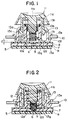
- a substate 5 a fixed contact point 6 provided on the substrate 5, a spacer 7, a flixible member 8 provided over the spacer 7, a movable electrode 9 attached to the lower surface of the flexible member opposite to the fixed electrode 6, a switch holding frame 10, a key 11 having a key head 11d, a stem 11a projecting from the central portion of the lower surface of the key head 11d, and legs 11b extending downward from the key head 11d around the stem 11a and each having a tapered claw 11c at the lower end thereof, a coil spring 12, and a key housing 13.
- the coil spring 12 has an upper large coil section 12a, a middle extension coil section 12b, an upper parallel section 12c, a small compression coil section 12d and a lower parallel section 12e, which are formed integrally in that order. A portion of one of the coils of the small compression coil section 12d is deformed radially outward to form a projecting part 12f.
- the key housing 13 has a bottom wall 13a, a tubular spring retainer 13b extending upright from the central portion of the bottom wall 13a and provided with a shoulder 13h in the upper end theeof, a substantially annular guide wall 13c surrounding the tubular spring retainer 13b, a stopping flange 13d inwardly extending from the upper end of the guide wall 13c, a flange 13e extending radially outward from the outer circumference of the guide wall 13c, and locking claws 13f projecting from the outer circumference of the bottom wall 13a.
- the key housing 13 is retained firmly on the frame 10 by means of the flange 13e and the locking claws 13f clamping the frame 10 therebetween.
- the coil spring 12 is put in the tubular spring retainer 13b of the key housing with the lower parallel section 12e foremost to position the coil spring 12 in the tubular spring retainer with the large coil section 12a seated on the shoulder 13h formed in the upper end of the tubular spring retainer 13b. In this state, a small predetermined gap of l is formed between the lower parallel section 12e and the flexible member 8.
- the key 11 is put on the annular guide wall 13c of the key housing 13 with the tapered claws 11c of the legs 11b thereof on the stopping flange 13d, and then the key 11 is depressed so that the legs 11b are bent elastically to allow the tapered claws 11c of the legs 11b to slip into the interior of the annular guide wall 13c of the key housing 13 over the stopping flange 13d.
- the stem 11a of the key 11 is inserted in the middle extension coil section 12b of the coil spring 12 with the lower end thereof in abutment with the upper parallel section 12c formed between the middle extension coil section 12b and the small compression coil section 12d, and the tapered claws 11c of the key 11 engage the stopping flange 13d of the key housing 13.
- the middle extension coil section 12b is extended slightly, and hence the key 11 is urged upward through the stem 11a by the coil spring 12, whereby the tapered claws 11c are pressed against the inner surface of the stopping flange 13d to position the key 11.
- the projecting part 12f of the small compression coil section 12d of the coil spring 12 is in engagement with the protrusion 13g formed in the inner circumference of the tubular spring retainer 13b, so that the predetermined gap of l is formed between the lower parallel section 12e and the flexible member 8.
- a point A indicates a status in which the key 11 of the push-button switch is not depressed
- a point B indicates a status in which the key 11 is depressed to an extent where the projecting part 12f of the coil spring 12 has not yet moved down over the protrusion 13g and hence the small compression coil section 12d of the coil spring 12 is compressed
- a point C indicates a status in which the key 11 is depressed to an extent where resistance against the downward movement of the key 11 is increasing progressively
- the projecting part 12f of the coil spring 12 is deformed elastically and is almost moving down over the protrusion 13g
- a point D indicates a status in which the projecting part 12f of the coil spring 12 has just moved down over the protrusion 13g and hence the small compression coil section 12d of the coil spring 12 has extended, so that the flexible member 8 is depessed to bring the movable contact point 9 into contact with the fixed electrode 6 provided on the substrate 5, whereby the
- the pressure necessary for depressing the key 11 decreases from a pressure at the point C to a pressure at the point D, so that the operator is able to detect the closing of the switch by the sense of touch.
- the middle extension coil section 12b of the coil spring 12 is allowed to contract and the small compression coil section 12d of the coil spring 12 is allowed to extend, so that the key 11 is pushed upward by the contractive force of the middle extension coil section 12b and the recoiling force of the small compression coil section 12d, and the pressure acting on the flexible member 8 decreases. Consequently, the movable electrode 9 is separated from the fixed electrode 6 to open the switch.
- the projecting part 12f of the coil spring 12 engages the lower surface of the protrusion 13g. Since the contractive force of the middle extension coil section 12b is greater than a force necessary to move the projecting part 12b up over the protrusion 13g, the projecting part 12b moves up over the protrusion 13g. Consequently, the status changes from that indicated by the point E through those indicated by the points D and F to that indicated by the point A, namely, the initial status.
- the contact of the push-button switch is thus operated and the operator is able to detect the closing and opening of the switch by the sense of touch through the sensuous detection of the variation of the resistance against the depression of the key 11 which occurs when the projecting part 12f moves over the protrusion 13g.
- the push-button switch described hereinbefore is of a so-called membrane type having a flexible membrane (the flexible member 8) and a movable electrode (the movable electrode 9), the present invention is applicable also to a push-button switch of a capacitance type as shown in Fig. 6 having fixed electrode 15 provided on a substrate 5, and a movable electrode 16 attached to the lower parallel section 12e of a coil spring 12 similar to that of the first embodiment.
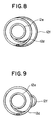
- Figs. 7 to 9 are plan views taken along X-X of the modified coil springs (upper portion thereof are same as that shown in Fig. 3 so that the lower portion thereof are taken along X-X of Fig. 3).
- the projecting part 12f of the small compression coil section 12d of the coil spring 12 may be an eccentric circular coil having a diameter greater than that of the rest of the coils of the small compression coil section 12d (Fig. 7), an elliptic coil (Fig. 8), a coil having a partial projecting part or a coil having any other suitable shape (Fig. 9).
- the protrusion 13g formed on the inner circumference of the tubular spring retainer 13b of the key housing may be an annular protrusion (Fig. 10) or a local protrusion (Fig. 11).
- a positioning slot 13i is formed in the upper end of the tubular spring retainer 13b and the coil spring 12 is put in the tubular spring retainer 13b with a stopping projection 12g formed at the free end of the coils of the large coil section 12a thereof engaging the slot 13i to fix the circumferential position of the coil spring 12 relative to the tubular spring retainer 13b so that the projection 12f of the coil spring 12 coincides with the protrusion 13g.
- a mechanism for giving a sensuous stimulus indicating the operation of a push-button switch can be constructed by a single coil spring and a protrusion formed on the inner circumference of a tubular spring retainer for retaining the coil spring without requiring any additional parts including an actuator having a complicated shape which is essential to the conventional push-button switch.
- the push-button switch of the present invention comprises a reduced number of parts, has a simple construction, enables the insertion of the coil spring and the key in the same direction in assembling the push-button switch facilitating the assembling process, and reduces the manufacturing cost of the push-button switch remarkably.
- the coil spring is a single member integrally having a plurality of functional sections, and the key and the coil spring are inserted in the key housing in the same direction, the key and the coil spring can be changed very simply for repair, which facilitates the maintenance of the push-button switch effectively.
Landscapes
- Push-Button Switches (AREA)
Claims (8)
- Commutateur à bouton-poussoir comprenant:
un substrat (5);
une électrode fixe (6) disposée sur le substrat (5);
une électrode mobile (9) disposée à l'opposé de l'électrode fixe (6);
un boîtier de touche (13) ayant un organe tubulaire de retenue de ressort (13b) vertical, formé dans la partie centrale de sa paroi inférieure (13a) et ayant une cavité (13h) formée dans son extrémité supérieure, et une paroi de guidage (13c) annulaire entourant l'organe tubulaire de retenue de ressort (13b) et ayant un rebord d'arrêt (13d) s'étendant sensiblement radialement vers l'intérieur, depuis son extrémité supérieure;
un ressort hélicoïdal logé dans l'organe de retenue de ressort (13b) du boîtier de touche (13), sa partie supérieure étant placée sur la surface inférieure de la cavité (13h) de l'organe tubulaire de retenue de ressort (13b) ;
une touche (11) pour actionner l'électrode mobile (9), ayant une tête de touche (11d), une tige centrale (11a) s'étendant vers le bas depuis la partie centrale de la surface inférieure de la tête de touche (11d), de manière à être insérée dans le ressort hélicoïdal (12), et des jambages (11b) formés autour de la tige (11a) de manière à s'étendre vers le bas depuis la surface inférieure de la tête de touche (11d) et pourvus chacun à leur extrémité inférieure d'une griffe effilée (11c), et montés de façon à coulisser axialement sur le boîtier de touche (13), la tige (11a) étant logée dans le ressort hélicoïdal (12) logé dans l'organe tubulaire de retenue de ressort (13b) du boîtier de touche (13) et avec les griffes effilées (11c) des jambages (11b) en prise avec la bride de butée (13d) de la paroi de guidage (13c) annulaire du boîtier de touche (13) ;
le ressort hélicoïdal (12) comprenant une section hélicoïdale (12a) de grand diamètre, placée sur ladite cavité (13h) de l'organe tubulaire de retenue de ressort (13b), une section hélicoïdale (12b) d'allongement moyen et de plus faible diamètre, de manière à s'insérer dans l'organe tubulaire de retenue de ressort (13b) pour permettre l'insertion d'une tige centrale de la touche (11), une section (12c) parallèle supérieure, ayant un premier diamètre réduit de manière à former butée pour ladite tige centrale (11a), une petite section hélicoïdale de compression (12d) et une section (12e) parallèle inférieure, qui sont formées d'un seul tenant dans cet ordre, une partie de la petite section hélicoïdale de compression (12d) faisant saillie de la petite section hélicoïdale de compression (12d) pour former une partie saillante (12f), une saillie (13g) est formée sur la circonférence intérieure de l'organe tubulaire de retenue de ressort (13b), la partie saillante (12f) du ressort hélicoïdal (12) vient au prise avec la surface supérieure de la saillie (13g) lorsque la touche (11) n'est pas enfoncée, la partie saillante (12f) du ressort hélicoïdal (12) se déplace sur le bas sur la saillie (13g) lorsque la touche (11) est enfoncée en allongeant la section hélicoïdale (12b) d'allongement moyen et en comprimant la petite section hélicoïdale de compression (12d), et la partie saillante (12f) est forcée à se déplacer vers le haut sur la saillie (13g) sous l'effet de la force de contraction de la section hélicoïdale (12b) d'allongement moyen et de la force de rappel de la petite section hélicoïdale de compression (12d), lorsque la touche (11) est libérée. - Commutateur à bouton-poussoir selon la revendication 1, dans lequel ladite électrode mobile (9) est disposée en regard de ladite électrode fixe (6), sur la surface inférieure d'un organe flexible (8) placé sur ledit substrat (1), avec un élément d'espacement (7) entre eux.
- Commutateur à bouton-poussoir selon la revendication 1, dans lequel ladite partie saillante (12f) est une partie d'un ressort hélicoïdal circulaire excentrique de diamètre supérieur à celui du restant des spires de ladite petite section hélicoïdale de compression (12d).
- Commutateur à bouton-poussoir selon la revendication 1, dans lequel ladite partie saillante (12f) est une partie d'un ressort hélicoïdale elliptique parmi les spires de ladite petite section hélicoïdale de compression (12d).
- Commutateur à bouton-poussoir selon la revendication 1, dans lequel ladite partie saillante (12f) est une partie saillante de l'une des spires de ladite petite section hélicoïdale de compression (12d).
- Commutateur à bouton-poussoir selon la revendication 1, dans lequel ladite saillie (13g) est une saillie annulaire.
- Commutateur à bouton-poussoir selon la revendication 1, dans lequel ladite saillie (13g) est une saillie locale, une saillie de butée (12g) est formée à I'extrémité libre des spires de la grande section hélicoïdale (12a) dudit ressort hélicoïdal (12), une fente de positionnement (13i) est formée dans l'extrémité supérieure de l'organe tubulaire de retenue de ressort (13b) dudit boîtier de touche (13), pour y recevoir la saillie de butée (12g) afin de positionner ledit ressort hélicoïdal (12) par rapport audit organe tubulaire de retenue de ressort (13b), de manière que la partie saillante (12f) dudit ressort hélicoïdal (12) coïncide avec la saillie (13g).
- Commutateur à bouton-poussoir selon la revendication 1, dans lequel ladite électrode fixe (6) consiste en deux électrodes (15) séparées et ladite électrode mobile (9) est fixée à l'extrémité inférieure dudit ressort hélicoïdal (12).
Applications Claiming Priority (2)
| Application Number | Priority Date | Filing Date | Title |
|---|---|---|---|
| JP4182988 | 1988-03-31 | ||
| JP41829/88U | 1988-03-31 |
Publications (3)
| Publication Number | Publication Date |
|---|---|
| EP0339209A2 EP0339209A2 (fr) | 1989-11-02 |
| EP0339209A3 EP0339209A3 (fr) | 1991-03-13 |
| EP0339209B1 true EP0339209B1 (fr) | 1995-05-17 |
Family
ID=12619161
Family Applications (1)
| Application Number | Title | Priority Date | Filing Date |
|---|---|---|---|
| EP89103656A Expired - Lifetime EP0339209B1 (fr) | 1988-03-31 | 1989-03-02 | Interrupteur à bouton-poussoir |
Country Status (3)
| Country | Link |
|---|---|
| US (1) | US4927990A (fr) |
| EP (1) | EP0339209B1 (fr) |
| DE (1) | DE68922654T2 (fr) |
Families Citing this family (26)
| Publication number | Priority date | Publication date | Assignee | Title |
|---|---|---|---|---|
| US5201824A (en) * | 1989-10-06 | 1993-04-13 | Alps Electric Co., Ltd. | Push button switch |
| US5120923A (en) * | 1989-10-06 | 1992-06-09 | Takafumi Kato | Push button switch |
| WO1991012621A1 (fr) * | 1990-02-16 | 1991-08-22 | Alphameric Keyboards Limited | Ameliorations concernant les appareils de commutation |
| GB2246325B (en) * | 1990-07-25 | 1994-01-26 | Behavior Tech Computer Corp | Key assembly |
| JP2557557Y2 (ja) * | 1991-02-12 | 1997-12-10 | ミネベア株式会社 | キースイッチ |
| US5172805A (en) * | 1991-05-23 | 1992-12-22 | Northern Telecom Limited | Pushbutton and carrying member combination for operating an electronic switching device |
| US5145058A (en) * | 1991-07-16 | 1992-09-08 | Lee Sam San | Notebook computer key |
| US5306886A (en) * | 1992-06-15 | 1994-04-26 | Smk Co., Ltd. | Keyboard switch |
| EP0587406B1 (fr) * | 1992-09-09 | 1997-11-12 | Matsushita Electric Industrial Co., Ltd. | Dispositif d'interrupteur à poussoir à combinaison |
| JPH0648138U (ja) * | 1992-12-02 | 1994-06-28 | エスエムケイ株式会社 | 2軸型キーボードスイッチ |
| JP2593409Y2 (ja) * | 1992-12-02 | 1999-04-12 | エスエムケイ株式会社 | キーボードスイッチ |
| US5389755A (en) * | 1993-10-27 | 1995-02-14 | Chen; Pao-Chin | Computer key switch device |
| US5510583A (en) * | 1994-03-18 | 1996-04-23 | Eaton Corporation | Assembly for sequential switching |
| JP2742884B2 (ja) * | 1994-11-22 | 1998-04-22 | 新晃電機株式会社 | 押釦スイッチにおける押釦のクリップ機構 |
| US5710397A (en) * | 1995-08-04 | 1998-01-20 | Acer Peripherals, Inc. | Switch actuator for membrane switch |
| JP2005183306A (ja) * | 2003-12-22 | 2005-07-07 | T An T:Kk | プッシュスイッチの押しボタン構造 |
| CN101516167B (zh) * | 2008-02-18 | 2011-11-09 | 鸿富锦精密工业(深圳)有限公司 | 电子设备 |
| FR2937789B1 (fr) * | 2008-10-28 | 2010-12-31 | Thales Sa | Clavier a longue course de touches et a sensation tactile amelioree |
| EP2727245A1 (fr) * | 2011-06-29 | 2014-05-07 | TouchSensor Technologies, LLC | Interface mécanique d'un capteur tactile |
| KR20130027304A (ko) * | 2011-09-07 | 2013-03-15 | 삼성전자주식회사 | 컨트롤 패널 어셈블리 및 이를 구비한 세탁물 처리 장치 |
| TWI607476B (zh) | 2016-02-03 | 2017-12-01 | 達方電子股份有限公司 | 按鍵結構 |
| MX2020007640A (es) * | 2018-01-19 | 2020-09-14 | Lutron Tech Co Llc | Teclado con botones iluminados. |
| CA3132341A1 (fr) * | 2019-03-25 | 2020-10-01 | Covidien Lp | Systemes chirurgicaux robotiques a commutateur electrique pour fixation d'instrument |
| CN114334512B (zh) * | 2021-07-08 | 2024-03-15 | 光宝科技股份有限公司 | 按键结构 |
| KR20230029099A (ko) * | 2021-08-23 | 2023-03-03 | 삼성전자주식회사 | 전자 장치 및 그 제어 방법 |
| WO2024007255A1 (fr) * | 2022-07-07 | 2024-01-11 | 武汉领普科技有限公司 | Commutateur mural intelligent, commutateur intelligent sans fil et bâti de montage de commutateur |
Family Cites Families (10)
| Publication number | Priority date | Publication date | Assignee | Title |
|---|---|---|---|---|
| US3379851A (en) * | 1966-02-09 | 1968-04-23 | United Carr Inc | Pushbutton using three stage unitary spring as a contactor means |
| US3604878A (en) * | 1969-05-22 | 1971-09-14 | Korry Mfg Co | Latch mechanism for releasably engaging pushbutton caps in electrical devices |
| US3856998A (en) * | 1973-06-01 | 1974-12-24 | Burroughs Corp | Keyboard switch assembly with improved operating means |
| DE2545640C2 (de) * | 1975-10-11 | 1982-04-22 | Inter Control Hermann Köhler Elektrik GmbH & Co KG, 8500 Nürnberg | Rückstelleinrichtung für Temperaturbegrenzer |
| US4034177A (en) * | 1976-11-19 | 1977-07-05 | Burroughs Corporation | Plunger-actuated, lost motion switch with tactile feedback |
| US4529848A (en) * | 1981-11-05 | 1985-07-16 | Cherry Electrical Products Corporation | Switch with conical spring actuator |
| EP0117732A3 (fr) * | 1983-03-01 | 1986-09-24 | Plessey Overseas Limited | Boutons poussoirs |
| JPS6233123U (fr) * | 1985-08-14 | 1987-02-27 | ||
| DE3622962A1 (de) * | 1986-07-09 | 1988-01-21 | Schadow Rudolf Gmbh | Drucktastenschalter, insbesondere tastschalter |
| EP0261702A1 (fr) * | 1986-08-27 | 1988-03-30 | Koninklijke Philips Electronics N.V. | Interrupteur avec contacts en forme de fil |
-
1989
- 1989-03-02 DE DE68922654T patent/DE68922654T2/de not_active Expired - Fee Related
- 1989-03-02 EP EP89103656A patent/EP0339209B1/fr not_active Expired - Lifetime
- 1989-03-03 US US07/319,140 patent/US4927990A/en not_active Expired - Lifetime
Also Published As
| Publication number | Publication date |
|---|---|
| US4927990A (en) | 1990-05-22 |
| DE68922654D1 (de) | 1995-06-22 |
| EP0339209A3 (fr) | 1991-03-13 |
| EP0339209A2 (fr) | 1989-11-02 |
| DE68922654T2 (de) | 1995-10-05 |
Similar Documents
| Publication | Publication Date | Title |
|---|---|---|
| EP0339209B1 (fr) | Interrupteur à bouton-poussoir | |
| US4733036A (en) | Coil spring for key switch | |
| CN102741961B (zh) | 操作开关 | |
| EP0224006B1 (fr) | Commutateurs à bouton-poussoirs utilisant des ressorts en forme de dôme | |
| US2817725A (en) | Overtravel mechanism for sensitive switches | |
| JPS59146113A (ja) | プッシュボタンスイッチ | |
| US4417115A (en) | Switch actuating assembly having improved cams and plural modes | |
| US4831223A (en) | Push-button switch | |
| JPH0575929U (ja) | 押ボタンスイッチ | |
| US5004880A (en) | Click-type push button switch with improved leaf spring | |
| JPH0648133U (ja) | キーボードスイッチ | |
| US6774330B2 (en) | Multi-stage push button switch apparatus | |
| KR200162409Y1 (ko) | 키이보오드 스위치 | |
| US6570113B2 (en) | Key switch | |
| CA1312896C (fr) | Bouton-poussoir, notamment pour commutateur verrouillable | |
| US4145590A (en) | Actuation for sequentially operating plural switches | |
| US4301345A (en) | Key switch actuation by torsion spring | |
| US4385214A (en) | Interlock pushbutton assembly | |
| CN215527489U (zh) | 一种用于双电源自动转换开关的动触头组件 | |
| JP3526561B2 (ja) | プッシュロックスイッチ | |
| JPH0439615Y2 (fr) | ||
| SU1751823A1 (ru) | Привод кнопочного выключател | |
| KR102297397B1 (ko) | 직선이동 및 복귀장치 | |
| JPH069396Y2 (ja) | 押しボタンスイッチ | |
| JPH0428123A (ja) | 押釦スイッチ |
Legal Events
| Date | Code | Title | Description |
|---|---|---|---|
| PUAI | Public reference made under article 153(3) epc to a published international application that has entered the european phase |
Free format text: ORIGINAL CODE: 0009012 |
|
| AK | Designated contracting states |
Kind code of ref document: A2 Designated state(s): DE FR GB |
|
| PUAL | Search report despatched |
Free format text: ORIGINAL CODE: 0009013 |
|
| AK | Designated contracting states |
Kind code of ref document: A3 Designated state(s): DE FR GB |
|
| 17P | Request for examination filed |
Effective date: 19910807 |
|
| 17Q | First examination report despatched |
Effective date: 19940120 |
|
| GRAA | (expected) grant |
Free format text: ORIGINAL CODE: 0009210 |
|
| AK | Designated contracting states |
Kind code of ref document: B1 Designated state(s): DE FR GB |
|
| REF | Corresponds to: |
Ref document number: 68922654 Country of ref document: DE Date of ref document: 19950622 |
|
| ET | Fr: translation filed | ||
| PLBE | No opposition filed within time limit |
Free format text: ORIGINAL CODE: 0009261 |
|
| STAA | Information on the status of an ep patent application or granted ep patent |
Free format text: STATUS: NO OPPOSITION FILED WITHIN TIME LIMIT |
|
| 26N | No opposition filed | ||
| PGFP | Annual fee paid to national office [announced via postgrant information from national office to epo] |
Ref country code: GB Payment date: 19980223 Year of fee payment: 10 |
|
| PGFP | Annual fee paid to national office [announced via postgrant information from national office to epo] |
Ref country code: DE Payment date: 19980306 Year of fee payment: 10 |
|
| PGFP | Annual fee paid to national office [announced via postgrant information from national office to epo] |
Ref country code: FR Payment date: 19980310 Year of fee payment: 10 |
|
| PG25 | Lapsed in a contracting state [announced via postgrant information from national office to epo] |
Ref country code: GB Free format text: LAPSE BECAUSE OF NON-PAYMENT OF DUE FEES Effective date: 19990302 |
|
| GBPC | Gb: european patent ceased through non-payment of renewal fee |
Effective date: 19990302 |
|
| PG25 | Lapsed in a contracting state [announced via postgrant information from national office to epo] |
Ref country code: FR Free format text: LAPSE BECAUSE OF NON-PAYMENT OF DUE FEES Effective date: 19991130 |
|
| REG | Reference to a national code |
Ref country code: FR Ref legal event code: ST |
|
| PG25 | Lapsed in a contracting state [announced via postgrant information from national office to epo] |
Ref country code: DE Free format text: LAPSE BECAUSE OF NON-PAYMENT OF DUE FEES Effective date: 20000101 |